


Whirlpool 5GT118FFEW, 5MT519SFEG, 5WT519SFEG, 5WT519SFEW, ART308FFDB Installation Instructions
...Installation
G U I D E
Table of Contents |
|
(complete) ................... |
2 |
Requesting Assistance |
|
or Service ....................... |
2 |
Important Information ... |
3 |
Before You Begin .......... |
4 |
Installing the |
|
Ice Maker ........................ |
6 |
Installing the |
|
Water Line .................... |
17 |
Final Installation .......... |
23 |
Starting the |
|
Ice Maker ...................... |
25 |
Troubleshooting .......... |
26 |
MODULAR ICE MAKER KIT
2181913D |
www.whirlpool.com |
|
Table of Contents
Requesting Assistance or Service |
...................2 |
Important Information ...................................... |
3 |
Before You Begin .............................................. |
4 |
Tools ................................................................... |
4 |
Installation notes ................................................ |
4 |
Important safety instructions ............................. |
4 |
Components ...................................................... |
5 |
Installing the Ice Maker................................... |
6 |
Making preparations ......................................... |
6 |
Side-by-side models ......................................... |
7 |
Top/bottom freezer models ............................... |
9 |
Installing the tubing clips ................................. |
11 |
Preparing the water valve tubing |
|
(for bottom freezers only).................................. |
12 |
Mounting the water valve ................................. |
13 |
Connecting the water valve tubing................... |
14 |
Mounting the ice maker ................................... |
15 |
Routing the copper tubing ................................ |
16 |
Installing the shut-off valve ............................... |
17 |
Connecting the copper tubing |
|
to the shut-off valve .......................................... |
18 |
Connecting the copper tubing |
|
to the water valve............................................... |
21 |
Turning the water on ......................................... |
22 |
Final Installation............................................... |
23 |
Installing the access cover |
|
and forming the copper tubing ......................... |
23 |
Connecting the power/ |
|
leveling the unit ................................................. |
24 |
Starting the Ice Maker ...................................... |
25 |
Troubleshooting ................................................ |
26 |
Operational notes ............................................. |
26 |
Troubleshooting chart ....................................... |
26 |
The modular ice maker service sheet ............... |
27 |
Ice maker replacement parts list ....................... |
28 |
Requesting Assistance or Service
If you need assistance, contact your dealer, or call the Whirlpool Consumer Assistance Center toll-free, 18006932538, 24 hours a day.
2

Important Information
The following information is used throughout this Installation Guide. Read it carefully so you are familiar with it.
Your safety and the safety of others are very important.
many important safety messages in this manual and on your appliance. Always read and obey all safety
safety alert symbol.
alerts you to potential hazards that can kill or hurt you and others.
messages will follow the safety alert symbol and either the word “DANGER” or “WARNING.” mean:
 DANGER
  WARNING
You can be killed or seriously injured if you don't immediately follow instructions.
You can be killed or seriously injured if you don't follow instructions.
All safety messages will tell you what the potential hazard is, tell you how to reduce the chance of injury, and tell you what can happen if the instructions are not followed.
This Installation Guide gives you complete instructions on how to install the Ice Maker Kit in your refrigerator-freezer and connect a water line to it. Please read the guide
carefully and follow the instructions exactly as described. Also, make sure that you observe all of the “safety” instructions.
This kit is designed so that almost anyone can install it; however, a certain amount of mechanical ability is required.
Before you start to install your Ice Maker Kit, you will have to purchase a copper tubing kit that contains a “Regular Valve and Clamp
Assembly” (for refrigerators with an automatic ice maker, or self-filling trays). The kit contains all of the hardware necessary to connect
your ice maker to the water supply. You can purchase one at most hardware or plumbing supply stores.
DO NOT USE PIERCING-TYPE, OR 3⁄16" SHUT-OFF VALVES. They reduce the flow of water to the ice maker, and are easily clogged.
DO NOT USE POLYETHYLENE TUBING to connect the ice maker to the water line. Use only 1⁄4" (O.D.) copper tubing.
CUSTOMER INSTALLATION IS NOT WARRANTED BY THE REFRIGERATOR OR ICE MAKER MANUFACTURER.
3
Before You Begin
Tools
Gather required tools and parts before starting installation. Read and follow the instructions provided with any tools listed here.
1.Regular screwdriver
2.Phillips screwdriver
3.7⁄16" and 1⁄2" open-end wrenches (or an adjustable wrench)
4.Pliers
5.1⁄4" nut driver
6.Hand drill with 1⁄4" drill bit
7.Small hand level (optional)
8.Small 3⁄4-round file
9.Tubing cutter
10.Center punch
11.Hammer
12.Scissors
13.Ruler
14.Step stool (optional)
Installation notes
1.Follow the instructions carefully. Read through the entire step so that you understand it before you perform it.
2.The illustrations in this Installation Guide are meant to clarify the installation steps you need to perform. For each set of steps shown, refer to the diagram immediately beside or below the text for clarification. Some illustrations also contain “DETAILS.” DETAILS are contained in bubbles alongside the larger illustration. A DETAIL shows a close-up illustration of a certain portion of a diagram or an illustration of a specific step
you are to perform. DETAILS are labeled A, B, or C and are clearly referenced in each step.
3.When you are instructed to install a part, position the part as shown in the illustration.
4

Components
Remove the contents from the shipping carton and set them on a table where they can be easily identified and located. Check all of the components in the kit against the following list to help you become familiar with them. When you identify a component, place a check mark
( 3) after it. The KEY numbers correspond to the “Component Illustrations.”
IMPORTANT: When you remove the water valve and flexible tubing from the styrofoam packing insert, do not remove the tubing from the valve. It has been factory-installed and leak-tested. Do not disturb the compression nut that connects the tubing to the valve, or the valve may leak after you connect it to the water supply.
Do not discard any of the packing material until |
COMPONENT ILLUSTRATIONS |
||||
you account for all of the components. If you |
|
|
|
||
need to order a replacement part for the Ice |
|
|
|
||
Maker, a replacement parts list is provided on |
|
|
|
||
page 28. |
|
|
|
|
|
KEY |
QTY. |
DESCRIPTION |
|
|
|
1 |
1 |
Ice maker |
|
|
|
2 |
1 |
Ice bucket |
|
|
|
3 |
1 |
Water valve w/tubing |
|
|
|
4 |
1 |
Fill tube |
|
|
|
5 |
1 |
Gasket * (and) ** only |
|
|
|
6 |
1 |
21⁄2" (short) extension tube |
|
|
|
7 |
1 |
6" (long) extension tube* |
|
|
|
8 |
2 |
Ice maker clips* |
|
|
|
9 |
2 |
Tubing clips |
|
|
|
10 |
1 |
Metal water tube insert |
|
|
|
11 |
1 |
Water valve tubing clamp |
|
|
|
12 |
4 |
1⁄2" hex-head sheet-metal screws |
|
11 |
|
13 |
2 |
1⁄2" hex-head machine screws |
|
12 |
|
14 |
2 |
3⁄4" hex-head sheet-metal screws |
|
|
|
|
|
|
|||
15 |
1 |
4" extension tube** |
14 |
|
13 |
16 |
1 |
33⁄8" extension tube*** |
|
||
17 |
1 |
Bracket fill tube*** |
15 |
|
16 |
18 |
1 |
Grommet Condenser** |
|
||
17
* For installation in Side-By-Side Models only. |
18 |
|
**For installation in 14 to 18 Cubic Foot Top Freezer Models.
***For installation in 11 Cubic Foot Top Freezer Models only (kit 24ECKMF).
5

Installing the Ice Maker
Making preparations
Refer to the illustration below for the following steps.
1.Carefully pull the refrigerator away from the wall so that you can easily access the rear panel.
 WARNING
Electrical Shock Hazard Disconnect power before installing ice maker.
Failure to do so can result in death or electrical shock.
4.On an appliance with a bottom freezer, remove the slide-out basket, the ice cube trays, and the wire ice cube holder
(if necessary, refer to your “Use and Care Guide” for the procedure). Set these items aside.
On top-mount models without a full-width freezer shelf, remove the ice tray shelf. Place the shelf aside, as you will use it later to support the ice bucket.
If you have a side-by-side model refrigerator, proceed to “Side-by-side models” on page 7. If you have a refrigerator with a top or
a bottom freezer, proceed to “Top/bottom freezer models” on page 9.
NOTE: The work area for all three model refrigerator-freezers is shown in DETAIL A below.
Detail
2.Unplug Refrigerator or disconnect power.
IMPORTANT: If you have a side-by-side model refrigerator-freezer, be careful when you open the freezer door to work inside that you do not force the door against the stop at the bottom of the door. If you bend the stop, the door will not close properly.
3.On appliances with a top or a bottom freezer, open the freezer door and remove all of the food items from inside the freezer compartment.
|
|
|
|
You will be |
|
left side |
working in |
|
of freezer |
these areas |
|
compartment |
|
|
For side-by-side units, you should only have to remove food items from the top half of the freezer section.
This should give you enough room to access the areas to install
the ice maker.
Rear wall |
Power cord plug and
receptacle
Rear wall |
Rear wall |
Power |
Power |
cord |
cord |
plug and |
plug and |
receptacle |
receptacle |
Top freezer model |
Bottom freezer model |
Side-by-side model |
Work areas on the three model refrigerator-freezers
6
Side-by-side models
Refer to the side diagram for the following steps. You will be working inside the freezer compartment.
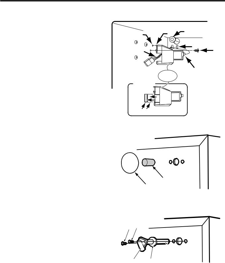
1.Remove the phillips screw from the ice maker wiring cover and remove the cover.
2.Refer to DETAIL A, and with a pair of pliers, break away the tabs from the wiring cover and discard them.
3.Insert the blade of a small screwdriver under the edge of the round hole plug for the fill tube, (located at the back of the freezer liner), and pry it out. You can discard the plug.
Refer to the side diagram for the following steps. You will be working on the outside at the rear of the cabinet.
1.In the upper right corner of the cabinet, peel off the label that is over the fill tube hole.
2.Pull the foam insert out of the fill tube hole and discard it.
Refer to the side diagram for the following steps.
1.Locate the fill tube and the round foam gasket from the ice maker kit (the gasket may already be installed on the fill tube). If not already done, slide the gasket over the end of the fill tube.
2.Insert the fill tube through the hole in the rear of the refrigerator with the spout facing down, and secure it with two 1⁄2" hex-head sheetmetal screws.
Insert pin |
|
|
|
into hole |
Pin |
Hole cover |
|
Hole |
|
|
|
|
|
|
|
Wiring |
|
Slot |
Phillips |
harness |
|
|
screw |
|
|
|
|
|
|
Tab |
Insert tab |
|
|
into slot |
Wiring
cover
DETAIL A
Break off and discard
Ice maker wiring cover
Remove this label for Ice Maker in allation
Foam insert
Label
Removing the label and foam plug
1⁄2" hex-head sheet-metal screws
 Fill tube
Spout Foam gasket
Installing the fill tube/gasket
7

Refer to the side diagram for the following step. You will be working inside the freezer compartment.
1.Install the plastic extension by sliding it over the fill tube as far as it will go.
Refer back to the side diagram for the following step.
2.Position the wiring harness so that it is through the slot in the wiring cover. Insert the tab at the back of the wiring cover into the freezer liner slot. Press the pin on the side of the wiring cover into the hole in the side of the freezer liner so it locks into place. Secure the wiring cover with the phillips screw you removed earlier.
Proceed to “Installing the tubing clips” on page 11.
 Fill tube
Slot
Wiring harness
Long fill
tube extension 

Installing the long fill tube extension
|
Insert pin |
|
|
|
into hole |
Hole cover |
|
|
Pin |
|
|
Hole |
|
|
|
|
|
|
|
Wiring |
|
Slot |
Phillips |
harness |
|
|
screw |
|
|
Tab |
Insert tab |
|
|
|
|
|
|
|
into slot |
|
Wiring |
|
|
|
cover |
|
|
Break off and discard
Replacing the ice maker wiring cover
8
Top/bottom freezer models
Refer to the side diagrams for the following 2 steps. You will be working inside the freezer compartment.
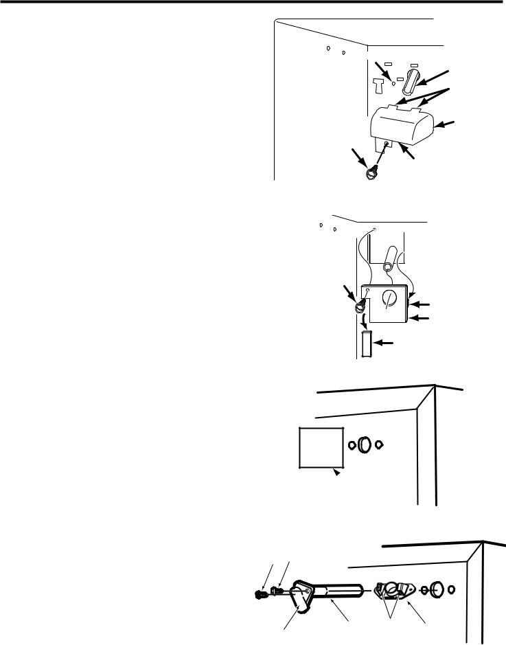
1.On models with a open-top ice maker fill tube and wiring cover:
Remove the screw from the ice maker wiring cover.
Squeeze top and bottom to loosen snaps. Remove and discard ice maker
wiring cover.
On models with a flat cover:
Remove the screw from the ice maker wiring cover.
Unhook the right side tab from the edge of the back cover. Remove ice maker wiring cover.
Look at the back side of the flat wiring cover and note the grooved lines. Use a pair of pliers and bend the areas inside the grooved lines back and forth until they break away from the wiring cover.
2.Pull the 4-wire ice maker harness out from behind the freezer’s back cover as far as possible, and hang it over the edge of the cutout. Do not remove any other wiring from the cutout.
Refer to the side diagrams for the following step. You will be working on the back of the refrigerator cabinet.
1.On the back of the cabinet, peel off the label that is over the fill tube hole.
On 11 Cubic Foot Top Freezer Models ONLY (kit 24ECKMF)
Install "Bracket Fill Tube" in the refrigerator back. Use holes in the back of refrigerator as reference.
Insert the fill tube through the hole in "Bracket Fill Tube" with Spout, twist and lock Spout in place. Verify the Spout is held in place by the "Bracket Fill Tube" ribs.
This type of fix will not require any screws in the Spout at all, screws will be inserted in the "Bracket Fill Tube".
Mounting hole
Open top fill tube
Snaps
Cover
Hex screw
Snap
Removing wiring cover with open-top fill tube
Mounting 

 hole
hole
Hex screw
Tab
Wiring cover
Break o and discard.
Removing the flat wiring cover
Remove this label for Ice Maker installation
 Label
Label
Removing the label
1⁄2" hex-head sheet-metal screws
Spout |
Fill tube |
Ribs |
Bracket |
|
|
||
|
|
|
fill tube |
Installing the fill tube/bracket fill tube (11 cubic foot models)
9

Top/bottom freezer models (continued)
Refer to the side diagrams for the following steps.
1.(continued)
On 14 to 18 Cubic Foot Top Freezer and Bottom Freezer Models
Locate the fill tube and the round foam gasket from the ice maker kit (the gasket may already be installed on the fill tube). If not already done, slide the gasket over the end of the fill tube.
Insert the fill tube through the hole in the rear of the refrigerator with the spout facing down, and secure it with two 1⁄2" hex-head sheetmetal screws.
Refer to the side diagrams for the following steps. You will be working inside the freezer compartment.
1.Slide the plastic fill tube extension
(See components table on page 5) over the end of the fill tube as far as it will go
(see DETAIL A).
NOTE: The plastic fill tube extension is not required for models with open-top fill tube.
2.Flat wiring cover: Install the wiring cover over the fill tube with the wiring harness through the slot. Hook the tab in the side of the wiring cover into the slot in the back cover of the freezer, and secure the cover with the screw you removed earlier
(see DETAIL B).
1⁄2" hex-head sheet-metal screws
Fill tube
Spout Foam gasket
Installing the fill tube/gasket (14 to 18 cubic foot and Bottom Freezer models)
DETAIL A
|
Fill |
|
|
tube |
|
Wiring |
fill tube |
|
extension |
||
harness |
||
(See components |
||
|
||
|
table on page 5) |
|
Installing the fill tube extension |
||
|
DETAIL B |
|
Mounting |
|
|
hole |
|
|
|
Edge of |
|
|
cover |
|
Hex screw |
Tab |
|
 Route harness through slot and fill tube through hole
Route harness through slot and fill tube through hole
10
Installing the tubing clips
Refer to the side diagram for the following steps.
1.Remove the seven hex-head screws from the rear access cover, then remove the cover and set it aside.
NOTE: If you have a later unit with a metal panel, (see DETAIL A), remove the hex-head screw from the access cover. Discard the cover and its screw. Do not remove the 7 hex-head screws from the larger rear access cover.
2.Peel the backing from the adhesive sides of the tubing clips. Press the clips against the back of the cabinet in the right channel at the approximate locations shown in DETAIL B. Center the clips between the fill tube and the top of the access opening. Alternate fill tube designs ares shown in DETAIL C and DETAIL D (for 11 Cubic Foot Top Freezer Models with Fill Tube and Bracket Fill Tube).
If you have a bottom freezer, proceed to page 12. If you have a side-by-side (SXS) or a top freezer unit, proceed to page 13.
DETAIL C |
DETAIL D |
|||
Alternate |
Fill tube with |
|||
fill tube |
bracket fill tube |
|||
design |
(11 Cubic Foot Top |
|||
|
|
|
Freezer Models) |
|
|
|
|
Fill Tube |
Bracket |
|
|
|
Fill Tube |
|
|
|
|
|
|
|
Right |
|
Fill tube for |
channel |
|
top and SXS |
|
|
freezers only |
|
|
|
DETAIL B |
|
|
Tubing |
|
|
clip |
|
|
Top and SXS |
|
|
freezers |
|
Fill tube for bottom |
|
|
freezer models |
|
|
|
Tubing |
|
|
clip |
|
Remove 7 hex- |
Bottom |
|
freezers |
||
head screws |
||
|
||
from rear |
|
|
access cover |
|
Metal panel
Access cover
Remove hexhead screw from rear access cover
DETAIL A
Installing the tubing clips
11
Preparing the water valve tubing
(for bottom freezers only)
Refer to the side diagram for the following steps.
1.Untaped the coiled flexible tubing coming from the water valve and straighten it.
2.Starting at the top of the compression nut on the water valve, measure the tubing for 30", and mark the location on the tubing with a pen.
3.Use a pair of scissors or a hobby knife, and make an even cut across the water valve tubing at the 30" mark you made in the previous step. Discard the excess tubing.
CUT TUBING
HERE
MAKE AN
EVEN CUT
ACROSS 30" TOP
Compression nut
Water valve 


Preparing the water valve tubing (for bottom freezers only)
12

Mounting the water valve
Refer to the diagram below for the following steps.
NOTE: For 11 Cubic Foot Top Freezer Models only, use a wire tie to get together capillary tube and dryer. This should be done by installer before installing water valve, to make more room for water valve installation. Installer should move
all thin tubing to be in parallel with cabinet (refrigerator side wall). By doing this, we assure that NO COPPER TUBBING is above valve connector (see DETAIL A).
1.Locate the 2-pin water valve solenoid connector (with the brown and two white wires) that is taped to the main wiring harness at the lower right corner of the rear access (see DETAIL B).
Mounting the water valve
2.Refer to DETAIL C and insert the 2-pin connector over the water valve solenoid terminals as far as possible (if the harness is not long enough, break the tape holding it to the main harness). You can position the connector with the wires at either terminal.
3.Refer to DETAIL C and mount the water valve to the mounting holes in the cabinet frame with two 1⁄2" hex-head machine screws. Make sure that you tighten these two screws securely.
DETAIL A
Wire Tie
Valve connector
|
Dryer |
|
|
DETAIL B |
2-pin connector |
Brown |
|
|
|
|
|
(2) White |
|
|
|
DETAIL C |
|
2-pin connector |
1⁄2" hex-head |
|
|
|
machine screws |
Water valve |
|
13

Connecting the water valve tubing
Refer to the diagram below for the following steps.
1.Refer to the inset in DETAIL A and pull the plastic insert out of the fill tube spout and discard it.
2.Locate the water valve tubing clamp (from the ice maker kit), and note that one of the flanges is made for a threaded screw and the other side has a round hole. Position this clamp with the round hole side facing up, and slide it over the end of the spout (see DETAILS A, B and D). Thread a 1⁄2" hex-head sheet metal screw into the clamp with your fingers as far as possible. You will tighten the screw later.
3.Refer to DETAIL A, and position the metal water tube insert as shown, then press it all the way into the water valve tubing.
4.Refer to DETAIL B and D, and slide the end of the tubing into the end of the fill tube spout as far as it will go (if the tubing does not reach, pull as much as necessary up through the clips), then tighten the tubing clamp screw as much as possible. Pull on the tubing to make sure that it is secure. If it slides out of the spout, push it back in, and tighten the clamp screw further until the tubing is secure.
5.Press the tubing into the two clips
(see DETAIL C) you installed earlier on the back of the cabinet. You will connect the free end of the tubing later.
6.Pull any excess tubing near the fill tube down through the two clamps so it forms a straight line with a loop at the bottom of the water valve.
Insert end of tubing into this fill tube (for top/ SXS freezers)
Insert end of tubing into this fill tube (for bottom freezers) 
|
DETAIL B |
|
|
Fill tube |
|
|
Slide clamp |
|
|
over spout |
|
Top/SXS |
Fill tube |
|
spout |
||
freezers |
||
|
Tighten |
|
|
screw on |
Bracket |
|
spout as |
||
Fill tube |
||
much as |
||
|
||
possible |
Slide clamp |
|
Insert tubing |
over spout |
|
into spout |
|
|
as far as |
|
|
possible |
|
Water |
|
|
valve |
DETAIL A |
|
tubing |
||
|
Tighten screw on spout as much as
 possible
 Insert tubing into spout as far as possible
Tubing clip
DETAIL C
Bottom |
freezers |
|
Remove  plastic insert
INSET |
Fill tube |
|
|
|
spout |
|
Water valve |
|
tubing clamp |
|
1⁄2" hex-head |
|
sheet-metal |
|
screw |
Water tube insert |
|
Water valve |
|
tubing |
|
Connecting the water valve tubing to the fill tube
14

Mounting the ice maker
Refer to the side diagram for the following step.
1.Look at the ice maker’s fill cup and note that the rear of the cup has a “U” shaped groove (either of the sides may also be grooved). Use your fingers, (or a pair of pliers, if it is easier), and remove only the rear “knock-out” from the cup. Bend the area back and forth inside the groove until it breaks free. The fill tube will fit through this cutout when you install the ice maker.
Refer to the side diagram for the following steps.
1.Remove and discard the blank connector from the wiring harness. To remove it, lift the locking arm on the side of the blank connector so it is over the tab of the wiring harness connector, and pull the blank connector off.
2.Insert the end of a small-bladed screwdriver under the edges of each of the three ice maker mounting hole plugs in the side of the freezer liner, and pry them out of their holes. You can discard the plugs.
3.For Top/Bottom Freezers Only: Partially install two 3⁄4" hex-head sheet-metal screws into the two top mounting holes (shown in the diagram) of the freezer liner. You will hang the ice maker over these two screws later, so make sure that they protrude out far enough.
4.For Side-By-Side Models Only: Refer to DETAIL A and mount the two mounting clips (from the ice maker kit) to the top mounting holes of the freezer liner with two 3⁄4" hexhead sheet-metal screws. Make sure that both clips hang straight down and then tighten the screws.
 Remove knock-out
Fill cup at rear of ice maker
Removing the knock-out
|
DETAIL A |
SXS MODELS |
3⁄4" hex-head |
ONLY |
sheet-metal |
|
screws |
|
Ice maker |
|
clips |
Hole |
|
|
plugs |
|
|
Lift locking |
Tab |
|
|
||
arm over tab |
|
|
Blank connector |
Wiring |
|
harness |
||
(remove and |
||
connector |
||
discard) |
||
|
Installing the ice maker clips
15
Refer to the side diagrams for the following steps.
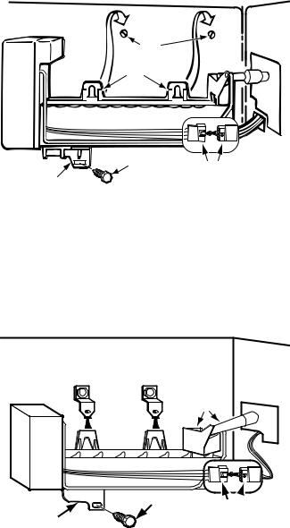
1.Position the ice maker inside the freezer compartment and connect its wiring connector to the wiring harness connector so they lock together (the locking arm will snap over the raised tab). The connectors will fit together only one way.
2.For Top/Bottom Freezers Only: Hang the ice maker over the two hex-head screws you installed earlier. Make sure that the bottom mounting bracket hole is aligned with the mounting hole in the freezer liner, then tighten the two top hex head screws. Be careful not to overtighten the screws.
Bottom |
screw |
connectors |
mounting |
|
|
bracket |
|
|
Mounting the ice maker (top and bottom freezers)
3.For Side-By-Side Models Only: Position the ice maker so that its top and bottom
mounting tabs are flat against the side of the freezer liner. Center the top tabs under the two mounting clips, and push the ice maker straight up so that the mounting clips snap over the tabs and lock into place (you should hear them “click” as they lock).
4.Mount the bottom bracket of the ice maker to the freezer liner mounting hole with a 3⁄4" hex-head sheet-metal screw.
|
|
Insert fill |
|
Ice maker |
|
tube into |
|
|
Slide tabs |
cup |
|
|
|
|
|
|
under clips |
|
|
Bottom |
|
1⁄2" hex-head |
Wiring |
mounting |
|
sheet-metal |
harness |
bracket |
|
screw |
connectors |
Mounting the ice maker (side-by-side models)
16
Installing the Water Line
Choosing a location
1.Open the copper tubing kit that you purchased earlier, and lay the contents neatly on a table where you can identify them easily. The parts from the kit that you will use are as follows:
1Regular Valve (not the steel-piercing type)
2Compression Sleeves
2 Compression Nuts
2 Clamps
2 Screws
2 Nuts
1 Gasket Seal *
1 Length of Coiled Copper Tubing
* - not needed for 11 Cubic Foot Top Freezer Models (24ECKMF kit)
NOTE: When you work with the soft copper |
|
|
|
|
|
|
|
|
|
|
|
|
|
|
|
|
|
|
|
|
|
|
||
tubing, be careful not to kink it. If you |
|
|
|
|
|
|
|
|
|
|
|
|
|
|
|
|
|
|
|
|
|
|
||
accidentally kink the tubing, do not use it. |
|
|
|
|
|
|
|
|
|
|
|
|
|
|
|
|
|
|
|
|
|
|
||
IMPORTANT: Do not install water line tubing in |
|
|
|
|
|
|
|
|
|
|
|
|
|
|
|
|
|
|
|
|
|
|
||
a location where the temperature may fall below |
|
|
|
|
|
|
|
|
|
|
|
|
|
|
|
|
|
|
|
|
|
|
||
freezing; otherwise, property damage could |
|
|
|
|
|
|
|
|
|
|
|
|
|
|
|
|
|
|
|
|
|
|
||
occur. |
|
|
|
|
|
|
|
|
|
|
|
|
|
|
|
|
|
|
|
|
|
|
||
2. Choose a suitable water pipe location to |
|
|
|
|
|
|
|
|
|
|
|
|
|
|
|
|
|
|
|
|
|
|
||
|
|
|
|
|
|
|
|
|
|
|
|
|
|
|
|
|
|
|
|
|
|
|||
install the water shut-off valve (see side |
|
|
|
|
|
|
|
|
|
|
|
|
|
|
|
|
|
|
|
|
|
|
||
diagram for some suggested locations). We |
|
|
|
|
|
|
|
|
|
|
|
|
|
|
|
|
|
|
|
|
|
|
||
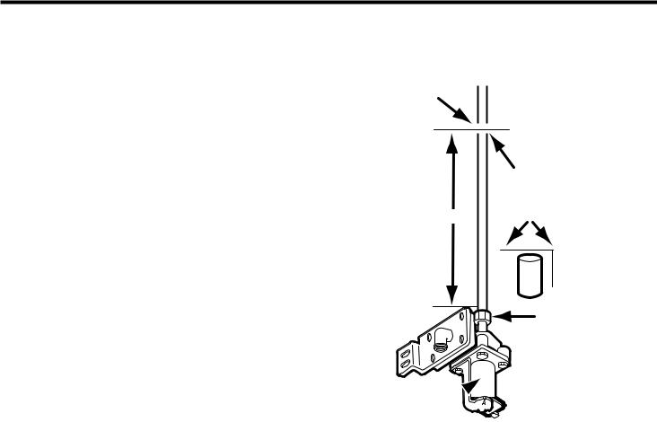
recommend installing the valve on a vertical |
|
|
|
|
|
|
|
|
|
|
|
|
|
|
|
|
|
|
|
|
|
|
||
|
|
|
|
|
|
|
|
|
|
|
|
|
|
|
|
|
|
|
|
|
|
|||
length of cold (not hot) water pipe that is |
|
|
|
|
|
|
|
|
|
|
|
|
|
|
|
|
|
|
|
|
|
|
|
|
|
Through |
Under sink |
Through |
In crawl |
||||||||||||||||||||
nearest your refrigerator. If a vertical length of |
||||||||||||||||||||||||
floor to |
to cold |
wall to |
space |
|||||||||||||||||||||
pipe is not nearby, you can use a horizontal |
basement |
water pipe |
utility room |
under |
||||||||||||||||||||
length of water pipe, however, you will have |
cold water |
|
|
|
|
|
|
cold water |
home to |
|||||||||||||||
pipe |
|
|
|
|
|
|
pipe |
cold water |
||||||||||||||||
to drill the access hole for the valve into the |
|
|
|
|
|
|
|
|
|
|
|
|
|
|
|
|
|
|
|
pipe |
||||
top or side of the pipe (not the bottom). This |
Typical water pipe locations |
will keep water in the pipe from flowing down |
|
onto the drill, and also keep sediment from |
|
collecting in the valve later. |
|
NOTE: Depending on the location of the |
|
horizontal pipe in relation to the floor and |
|
wall, drilling into it may not be possible. |
|
3.Drill a 3⁄8" hole through the floor or wall to the water pipe.
17

Routing the copper tubing
Refer to the side diagram for the following steps.
1.Uncoil the necessary length of copper tubing and straighten it, then route the end of the tubing through the access hole you drilled to the location you have chosen to install the shut-off valve. Straighten only enough of the copper tubing to reach this location. Leave the rest coiled near the access hole.
2.At this time, make sure that you have been supplied with enough tubing so that when you are finished connecting the water line, you will have enough coiled behind the refrigerator to easily move it forward far enough to clean behind it. Also make sure that the coils are large enough so that when the unit is pulled forward, the windings will not stretch too far and kink.
3.Turn off the cold water supply going to the water pipe where you will be installing the shut-off valve.
4.Open a cold water tap that is connected to the selected water pipe and bleed off the water pressure. Leave the tap open until after you complete the water line hook up.
5.Use a hammer and a center punch, and mark the location of the hole for the shut-off valve. If you are marking copper tubing, do not strike the punch hard enough to bend it.
|
Allow 4 to 5 feet of |
|
coiled tubing for |
|
moving refrigerator |
Back wall |
Drill 3⁄8" access |
|
hole for tubing |
|
Water |
|
valve |
Coiled copper tubing
Refrigerator
Drill 1⁄4" hole in front side of vertical water pipe
Routing the copper tubing
6.Install a 1⁄4" bit in the drill, and carefully drill an access hole through just the front side (not through both sides) of the cold water pipe.
7.Check the hole and make sure that you have drilled completely through one side of the pipe. The edges of the hole should be smooth and round. If necessary, use a small 3⁄4-round file to remove any rough edges from inside the hole, and any burrs from around the top of the hole.
18
 Loading...