


L.P. gas conversion instructions for PROFESSIONAL model series gas cooktops.
Use Kit No. 4455218, kit parts are in literature package supplied with cooktop.
Gas conversions from Natural gas to L.P. gas must be done by a qualified installer. Caution; Before proceeding with conversion, shut off the gas supply to the appliance prior to disconnecting the electrical power.
WARNING
This conversion kit shall be installed by a qualified service agency in accordance with the manufacturer’s instructions and all applicable codes and requirements of the authority having jurisdiction. If the information in these instructions is not followed exactly, a fire, explosion or production of carbon monoxide may result causing property damage, personal injury or loss of life. The qualified service agency is responsible for the proper installation of this kit. The installation is not proper and complete until the operation of the converted appliance is checked as specified in the manufacturer’s instructions supplied with this kit.
 WARNING
Explosion Hazard
Securely tighten all gas connections.
If connected to LP, have a qualified person make sure gas pressure does not exceed 14" water column.
Examples of a qualified person include licensed heating personnel, authorized gas company personnel, and authorized service personnel.
Failure to do so can result in death, explosion, or fire.
Parts provided with conversion kit 4455218: Orifice/Spud Package - 4455353 Conversion Instructions - 4455110 Conversion Label - 4455047
|
shutoff valve |
to cooktop |
“closed” |
position |
|
|
gas supply |
|
line |
1.Check that main gas supply line to the range has shut off and the power supply cord is disconnected.
|
burner cap |
|
ignitor |
burner |
|
electrode |
||
base |
||
|
gas tube opening
front of |
3.Remove burner cap. |
cooktop |
access cap |
|
|
|
|
|
|
|
|
|
|
pressure |
|
|
|
|
|
|
|
|
|
|
||
|
|
|
|
|
|
|
|
|
|
||
|
|
|
|
|
|
|
|
|
|
||
|
|
|
|
|
|
|
|
|
|
||
|
|
|
|
|
|
|
|
|
|
||
|
|
|
|
|
|
|
|
|
|
|
regulator |
|
|
|
|
|
|
|
|
|
|
|
gas-flow arrow |
|
|
|
|
|
|
|
|
|
|
|
|
|
|
|
|
|
|
|
|
|
|
|
pointing up |
|
|
|
|
|
|
|
|
|
|
|
|
|
|
|
|
|
|
|
|
|
|
|
|
2.Remove access cap by using a screwdriver or quarter, turning the access cap counterclockwise.
position of cap for a correctly converted regulator
The gas pressure regulator has two settings which are stamped on either side of the cap. Turn the cap and reinstall into regulator with the stamp “LP” visible from the outside of the regulator.
4.All |
orifice size stamp |
use a |
|
|
or color |
12,000 BTU, blue, size |
|
110 L.P. orifice. |
|
5. Use a nut driver (7mm) to remove existing orifice and replace with LP orifice.
Note: A small amount of tape inside the nut driver will help hold the orifice in the nut driver while changing the orifice.
The regulator must be checked at a minimum 1-inch (2.5 cm) water column above the set pressure. The inlet pressure to the regulator should be as follows for operation and checking the regulator setting:
L.P. GAS:
Minimum pressure 10 inches (25.4 cm) W.C. Supply pressure 14 inches (35.5 cm) W.C.
Testing below 1/2 psi (3.5 kPa) 14 inches (35.6 cm) W.C. (gauge) or lower.
The cooktop must be isolated from the gas supply piping system by closing its individual manual shutoff valve during any pressure testing of the gas supply piping system at test pressures equal to or greater than 1/2 psig (3.5 kPa).
|
|
|
|
|
|
|
|
|
|
|
|
electrode |
|
|
|||
|
|
cap |
|
|
|
|
|
|
|
|
|
|
|
|
|||
|
|
|
|
|
|
|
|
|
|
|
|
|
|
|
|
|
|
|
|
|
|
|
|
|
|
|
|
|
|
|
|
|
|
|
|
|
|
|
|
|
|
|
|
|
|
|
|
|
|
|
|
|
|
|
|
|
|
|
|
|
|
|
|
|
|
|
|
|
|
|
|
|
|
|
|
|
|
|
|
|
|
|
|
|
|
|
|
|
|
|
|
|
|
|
|
|
|
|
|
|
|
|
|
|
|
|
|
|
|
|
|
|
|
|
|
|
|
|
|
|
|
|
|
|
|
|
|
|
|
|
|
|
|
|
|
|
|
|
|
|
|
|
|
|
|
|
|
|
|
|
|
|
|
|
|
|
|
|
|
|
|
burner base
6. Replace burner cap.
7. Complete steps 4, 5 and 6 for each burner on the cooktop. Turn on gas.
Part No. 4455110
8. Leak testing of the appliance shall be conducted according to the following instructions:
Use a brush and liquid detergent to test all gas connections for leaks. Bubbles around connections will indicate a leak. If a leak appears, shut off gas valve controls and adjust connections. Then check connections again. NEVER TEST
FOR GAS LEAKS WITH A MATCH OR OTHER FLAME. Clean all detergent solution from cooktop.
Electronic Ignition System — initial lighting
Cooktop burners use electronic ignitors in place of standing pilots. When the cooktop control knob is pushed in and turned to the “LITE” position, the system creates a spark to light the burner. This sparking continues until the control knob is turned to the desired setting.
OFF
L
I
T
E
9. Check operation of the cooktop burners. Push in and turn each control knob to “LITE” position. The flame should light within 4 seconds. Do Not leave the knob in the “LITE” position after burner lights.
If burners do not light properly, turn control knob to the “OFF” position. Check that burner cap is in the proper position. Check that power supply cord is plugged in and that circuit breaker or house fuse has not blown. Check that the shutoff valve is in the “ON” position. Check operation again. If a burner does not light at this point, contact your KitchenAid dealer for assistance.
valve stem
10. Push in and turn each control knob to the “LO” (or simmer) position. The “LO” setting of each burner has been factory set to the lowest position available to provide reliable reignition of the burner. If it does not stay lit on the “LO” position, check “LO” position as follows:
a.Turn control knob to “LITE” until burner ignites.
b.Quickly turn control knob down to “LO” position.
c.If burner goes out, readjust valve as follows:
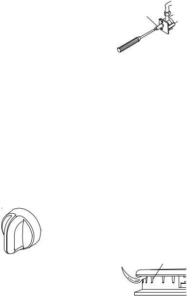
Remove the surface burner control knob. Insert a flat-blade screwdriver into the hollow valve stem and engage the slotted screw. Flame size can be increased or decreased by turning the screw. Adjust flame until you can quickly turn control knob from “HI” to “LO” position without extinguishing the flame. Flame should be as small as possible without going out.
13. For higher altitudes, no further adjustments are necessary. Derating the burners is also unnecessary.
14. Save the orifices removed from the unit along with these instructions for possible future use.
NATURAL GAS:
To convert back to Natural gas: Follow steps 3 through 11.
ports
typical surface burner flame at highest setting
11. Check flame on “HI” for a blue color. It should be clean and soft in character. No yellow tip, blowing or lifting of flame should occur. Occasional orange flashes are normal and reflect different elements in the air or gas.
12. Completely fill out conversion label (part no. 4455047) and attach the label to the bottom of the cooktop beside the rating tag. Do not cover the rating tag with the conversion label.
Part No. 4455110
 Loading...