


Whirlpool 4GWED4750, 4GWED4900, 4GWGD4900, 4GMEDC100, 4GMEDC300 Installation Instructions
...ELECTRIC OR GAS DRYER
INSTALLATION INSTRUCTIONS - 29" WIDE MODELS
INSTRUCTIONS D’INSTALLATION DU SECHE-LINGE ELECTRIQUE OU A GAZ - MODELES DE LARGEUR 29'' (74 CM)
SECADORA A GAS O ELÉCTRICA INSTRUCCIONES DE
INSTALACIÓN - MODELOS DE 29" DE ANCHO
Table of Contents
DRYER SAFETY.......................................................................... |
2 |
INSTALLATION REQUIREMENTS............................................. |
3 |
Tools and Parts................................................................... |
3 |
Location Requirements..................................................... |
4 |
Electrical Requirements.................................................... |
5 |
Gas Requirements............................................................. |
5 |
Install Leveling Legs.......................................................... |
6 |
Electrical Connection........................................................ |
7 |
VENTING................................................................................... |
10 |
Venting Requirements..................................................... |
10 |
Plan Vent System............................................................. |
11 |
Install Vent System........................................................... |
12 |
Make Gas Connection..................................................... |
13 |
Connect Vent.................................................................... |
13 |
Level Dryer........................................................................ |
14 |
COMPLETE INSTALLATION CHECKLIST............................... |
14 |
REVERSE DOOR SWING (OPTIONAL).................................... |
15 |
TROUBLESHOOTING............................................................... |
18 |
Table des matières
SECURITE DU SECHE-LINGE................................................. |
19 |
EXIGENCES D’INSTALLATION................................................ |
20 |
Outillage et pièces........................................................... |
20 |
Exigences d’emplacement.............................................. |
21 |
Spécifications électriques............................................... |
22 |
Exigences concernant l’alimentation en gaz................ |
23 |
Installation des pieds de nivellement............................. |
24 |
Raccordement électrique................................................ |
25 |
EVACUATION............................................................................ |
29 |
Exigences concernant l’evacuation............................... |
29 |
Planification du système d’evacuation.......................... |
30 |
Installation du circuit d’evacuation................................ |
31 |
Raccordement au gaz...................................................... |
31 |
Raccordement du conduit d’evacuation........................ |
32 |
Réglage de l’aplomb du sèche-linge.............................. |
33 |
ACHEVER L’INSTALLATION - LISTE DE VERIFICATION....... |
33 |
INVERSION DU SENS DE L’OUVERTURE |
|
DE LA PORTE (FACULTATIF)................................................... |
34 |
DEPANNAGE............................................................................. |
37 |
Índice
SEGURIDAD DE LA SECADORA............................................. |
38 |
REQUISITOS DE INSTALACIÓN.............................................. |
39 |
Piezas y herramientas..................................................... |
39 |
Requisitos de ubicación.................................................. |
40 |
Requisitos eléctricos....................................................... |
41 |
Requisitos de gas............................................................. |
42 |
Instalación de las patas niveladoras.............................. |
42 |
Conexión eléctrica........................................................... |
43 |
VENTILACIÓN........................................................................... |
46 |
Requisitos de ventilación................................................ |
46 |
Planificación del sistema de ventilación........................ |
47 |
Instalación del sistema de ventilación........................... |
48 |
Conexión del suministro de gas..................................... |
49 |
Conexión del ducto de escape....................................... |
50 |
Nivelación de la secadora............................................... |
50 |
LISTA DE CONTROL DE LA INSTALACIÓN TERMINADA..... |
51 |
CAMBIO DEL SENTIDO DE ABERTURA |
|
DE LA PUERTA (OPCIONAL)................................................... |
51 |
SOLUCIÓN DE PROBLEMAS.................................................. |
55 |
|
4GWED4750 |
|
|
4GWED4900 |
|
|
4GWGD4900 |
|
|
4GMEDC100 |
|
|
4GMEDC300 |
|
|
4GNED4400 |
|
W10454274C |
4GNED4600 |
|
4GAED4900 |
||
|
DRYER SAFETY
2
INSTALLATION REQUIREMENTS
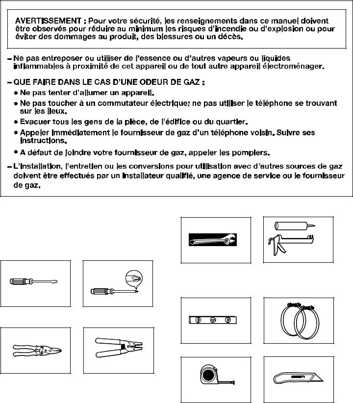
TOOLS AND PARTS
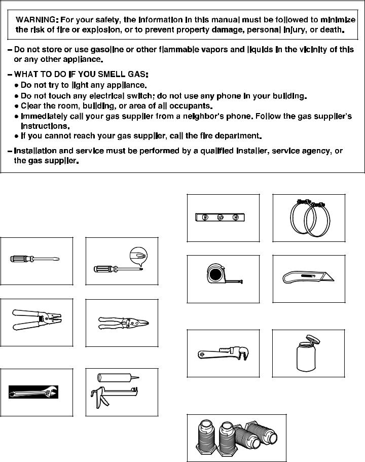
Gather the required tools and parts before starting installation. Read and follow the instructions provided with any tools listed here.
Tools needed for all installations:
Level
Vent clamps
Flat-blade screwdriver |
#2 Phillips screwdriver |
Tape measure |
Utility knife |
Tools needed for gas installations:
Wire stripper
(direct wire installations)
Tin snips
(new vent installations)
Adjustable pipe wrench |
Pipe joint compound |
that opens to 8" (204 mm) |
resistant to LP gas |
or 10" (254 mm) |
|
Parts supplied (all models):
Adjustable wrench that opens to 1" (25 mm) or hex-head socket wrench
Caulking gun and compound (for installing new exhaust vent)
Leveling legs (4)
Parts package is located in dryer drum. Check that all parts
are included.
3
Parts needed:
Check local codes. Check existing electrical supply and venting, and read “Electrical Requirements” and “Venting Requirements” before purchasing parts.
If using a power supply cord:
Use a UL listed power supply cord kit marked for use with clothes dryers. The kit should contain:
■■ A UL listed 30-amp power supply cord, rated 230 volt minimum. The cord should be type SRD or SRDT and be at least 4 ft (1.22 m) long. The wires that connect to the dryer must end in ring terminals or spade terminals with upturned ends.
■■ A UL listed strain relief.
For gas installation:
Check local codes and gas supplier, and read electrical, gas, and venting requirements before purchasing parts.
Gas supply line must have: ■■ Shutoff valve.
Rigid gas supply line must be:
■■ Minimum 1/2" (12.5 mm) ID pipe.
Flexible gas supply line must be:
■■ Minimum 3/8" (10 mm) ID approved flexible hose.
L.P. Gas Conversion:
A gas conversion kit, is available for purchase from your dealer. Full instructions are supplied with the kit. Conversion must be made by a competent technician.
Additional parts may be required, depending on your installation. Check local codes. Check existing venting and electrical and gas supply. Read “Electrical Requirements,” “Gas Requirements,” and “Venting Requirements” before purchasing parts.
LOCATION REQUIREMENTS
You will need:
■■ A location allowing for proper exhaust installation. See “Venting Requirements.”
■■ A separate 30 amp circuit.
■■ If you are using power supply cord, a grounded electrical outlet located within 2 ft (610 mm) of either side of dryer. See “Electrical Requirements.”
■■ A sturdy floor to support the total weight (dryer and load) of 200 lbs. (90.7 kg). The combined weight of a companion appliance should also be considered.
■■ Level floor with maximum slope of 1" (25 mm) under entire dryer. (If slope is greater than 1" [25 mm], install Extended Dryer Feet Kit, Part Number 279810.) If not level, clothes may not tumble properly and automatic sensor cycles may not operate correctly.
Do not operate your dryer at temperatures below 45°F (7°C). At lower temperatures, the dryer might not shut off at the end of an automatic cycle. Drying times can be extended.
The dryer must not be installed or stored in an area where it will be exposed to water and/or weather.
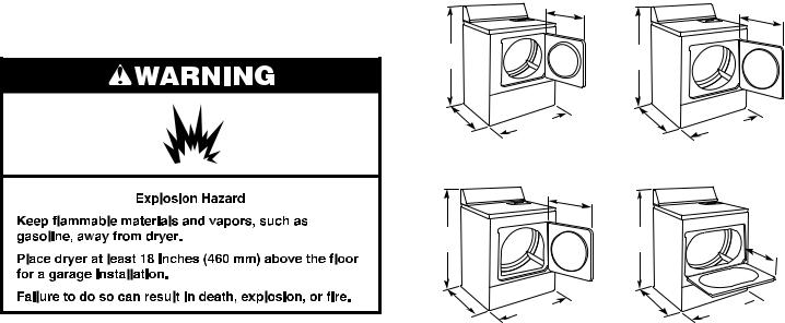
Check code requirements. Some codes limit, or do not permit, installation of the dryer in garages, closets, or sleeping quarters. Contact your local building inspector.
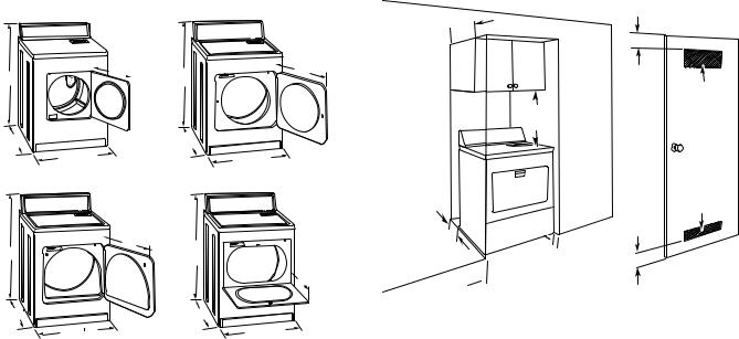
Installation clearances:
The location must be large enough to allow the dryer door to open fully.
Dryer Dimensions
151/4" |
223/4" |
|
(387 mm) |
||
(578 mm) |
||
|
433/8" |
433/8" |
(1102 mm) |
(1102 mm) |
*26" (660 mm)
433/8"
(1102 mm)
*273/4"
(705 mm)
29" |
*273/4" |
29" |
(737 mm) |
(705 mm) |
(737 mm) |
A |
|
B |
223/4" |
|
|
(578 mm) |
|
|
|
|
433/8" |
|
|
(1102 mm) |
|
29" |
*273/4" |
|
(705 mm) |
|
|
(737 mm) |
|
|
|
|
C |
|
D |
A.Small opening side-swing door
B.Large opening side-swing door
C.Wide opening side-swing door
D.Wide opening hamper door
133/4"
(349 mm
29"  (737 mm)
*Most installations require a minimum 5" (127 mm) clearance behind the dryer for the exhaust vent with elbow. See “Venting Requirements.”
Minimum spacing for recessed area or closet installation
The dimensions shown are for the minimum spacing allowed.
■■ Additional spacing should be considered for ease of installation and servicing.
■■ Additional clearances might be required for wall, door, and floor moldings.
■■ Additional spacing of 1" (25 mm) on all sides of the dryer is recommended to reduce noise transfer.
■■ For closet installation, with a door, minimum ventilation openings in the top and bottom of the door are required. Louvered doors with equivalent ventilation openings
are acceptable.
4
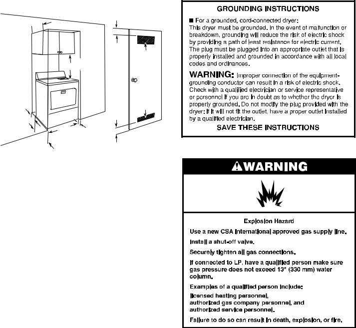
■■ Companion appliance spacing should also be considered.
14"max. (356 mm)
3" (76 mm)
48 in.2
18"
 (310 cm2)
(457 mm)
|
24 in.2 |
|
5" |
(155 cm2) |
|
3" |
||
(127 mm) |
||
(76 mm) |
||
|
||
29" |
1" |
|
(25 mm) |
||
(737 mm) |
27¾" (705 mm)
A.Recessed area
B.Side view - closet or confined area
C.Closet door with vents
*Additional spacing recommended
ELECTRICAL REQUIREMENTS
It is your responsibility:
■■ To contact a qualified electrical installer.
■■ To be sure that the electrical connection is adequate and in conformance with all local codes and ordinances.
■■ To supply the required 3, single phase, 230 volt, 60 Hz, AC only electrical supply on a separate 30-amp circuit (15 or 20 amp circuit for gas dryers), fused on both sides of the line. A time-delay fuse or circuit breaker is recommended. Connect to an individual branch circuit. Do not have a fuse in the neutral or grounding circuit.
■■ Do not use an extension cord.
■■ If codes permit and a separate ground wire is used, it is recommended that a qualified electrician determine that the ground path is adequate.
Electrical Connection
To properly install your dryer, you must determine the type of electrical connection you will be using and follow the instructions provided for it here.
If using a power supply cord:
Use a UL listed power supply cord kit marked for use with clothes dryers. The kit should contain:
■■ A UL listed 30-amp power supply cord, rated 230 volt minimum. The cord should be type SRD or SRDT and be at least 4 ft (1.22 m) long. The wires that connect to the dryer must end in ring terminals or spade terminals with upturned ends.
■■ A UL listed strain relief.
Connecting by direct wire:
Power supply cable must match power supply and be:
■■ Flexible armored cable or nonmetallic sheathed copper cable (with ground wire), covered with flexible metallic conduit. All current-carrying wires must be insulated.
■■ 10-gauge solid copper wire (do not use aluminum). ■■ At least 5 ft (1.52 m) long.
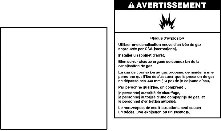
GAS REQUIREMENTS
OBSERVE ALL GOVERNING CODES AND ORDINANCES.
Gas supply:
Check that dryer is equipped with the correct burner for the particular type of gas supply. Burner information will be found on the model/serial rating plate in the door well of the dryer. If this information does not agree with the type of gas available, see your dealer.
5
Natural Gas:
This dryer is factory adjusted for use with NATURAL GAS (G20), and no further adjustment should be required at installation.
L.P. Gas:
This dryer is also certified for use with L.P. (propane or butane) gases with appropriate conversion. No attempt shall be made to convert the appliance from the gas specified on the model/serial rating plate for use with a different gas without consulting the serving gas supplier.
Conversion must be done by a qualified service technican.
Gas conversion kits are available for purchase from your dealer. Full instructions are supplied with the kit.
Supply Line Requirements
Provide a rigid gas supply line to the dryer location. It should be minimum 1/2" (12.5 mm) ID. When acceptable to the gas supplier and local codes, 3/8" (10 mm) ID rigid supply line may be used for lengths under 20 ft (6.1 m). Pipe-joint compounds resistant to the action of L.P. gas must be used.
Gas connection to the dryer itself should be made by means of a flexible gas hose suitable for the appliance and gas category in accordance with national installation regulations. If in doubt, contact the gas supplier. It should be minimum 3/8" (10 mm) ID.
A means of restraint should be used between the appliance and the wall to prevent straining of the rigid gas supply when the appliance is moved. An appropriate length of chain and a wall hook is recommended.
The dryer gas inlet connection is a 3/8" (10 mm) NPT thread. An adapter is supplied for conversion to standard ISO.228-1 thread 3/8" BSP (10 mm).
Check for leaks by using an approved noncorrosive leak detection solution. Bubbles will show a leak. Correct any leak found. A pressure measurement tapping is provided on the gas valve within the dryer, accessible after removal of the lower front panel.
The dryer must be disconnected from the gas supply piping system during any pressure testing of that system.
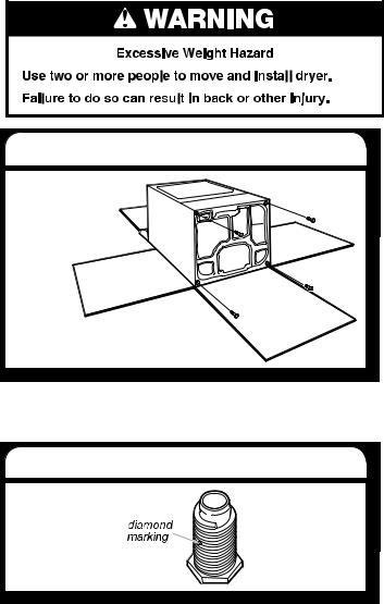
INSTALL LEVELING LEGS
1. Prepare dryer for leveling legs
To avoid damaging floor, use a large flat piece of cardboard from dryer carton; place under entire back edge of dryer. Firmly grasp dryer body (not console panel) and gently lay dryer down on cardboard.
2. Screw in leveling legs
Examine leveling legs, find diamond marking. Screw legs into leg holes by hand, use a wrench to finish turning legs until diamond marking is no longer visible.
Now stand the dryer on its feet. Slide the dryer until it is close to its final location. Leave enough room for electrical connection and to connect the exhaust vent.
6
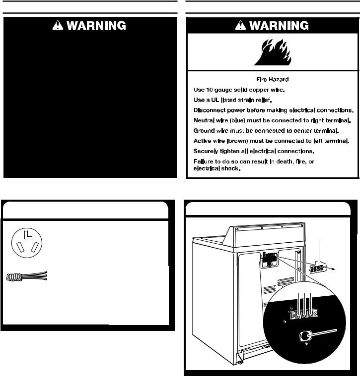
ELECTRICAL CONNECTION
Power Supply Cord
Electrical Connection Options
Direct Wire
1. Choose electrical connection type |
2. Remove terminal block cover |
Power supply cord (NEMA Type 10-30R): |
|
|
Go to steps 1-2 on page 8 for power supply |
A |
|
cord strain relief: then steps 3-5 for “Power |
||
|
||
Supply Cord Connection” section. Then go |
|
|
to “Venting Requirements.” |
|
|
Direct wire connection: Go to steps 1-2 |
|
|
on page 8 for direct wire strain relief: then |
|
|
steps 3-7 for “Direct Wire Connection” |
|
|
section. Then go to “Venting Requirements.” |
B C D |
|
NOTE: If local codes do not permit connection of a |
||
|
||
cabinet-ground conductor to neutral wire, go to “Direct |
|
|
Wire” section. This connection may be used with either |
|
|
a power supply cord or a direct wire connection. |
|
|
|
E |
|
|
Before you start, disconnect power. Remove terminal block |
|
|
cover (A). |
|
|
A. Terminal block cover |
|
|
B. Active screw |
|
|
C. Ground screw |
|
|
D. Neutral screw |
|
|
E. Strain relief hole |
7
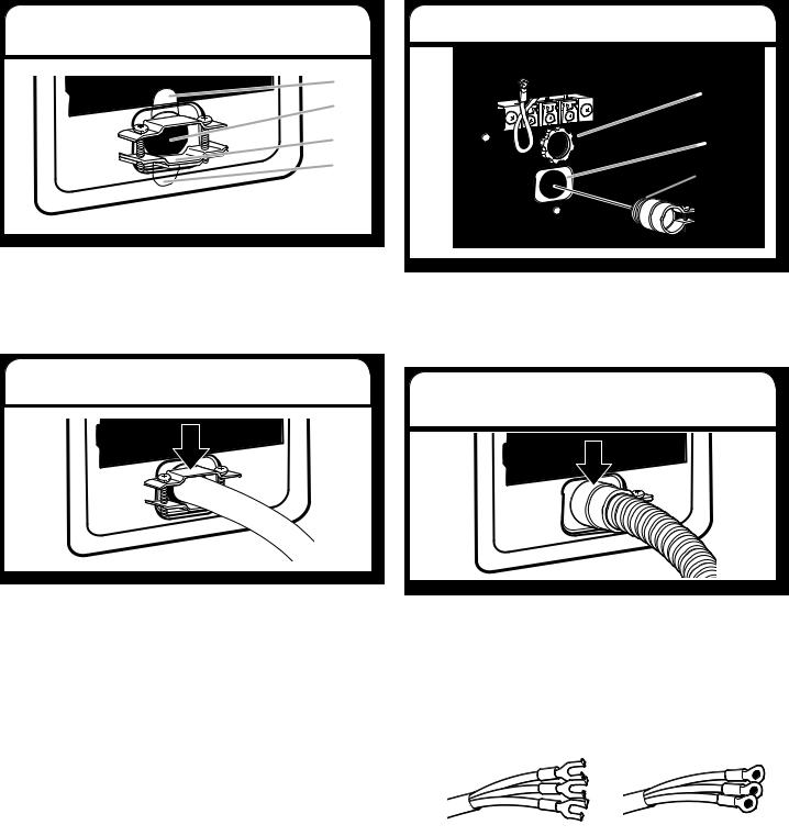
Install Strain Relief
Power supply cord strain relief
1. Attach power supply cord strain relief
A
B
C
D
Remove the screws from a 3/4" (19 mm) UL listed strain relief (UL marking on strain relief). Put the tabs of the two clamp sections (C) into the hole (B) below the terminal block opening so that one tab is pointing up (A) and the other is pointing down (D), and hold in place. Tighten strain relief screws just enough to hold the two clamp sections (C) together.
2. Attach power supply cord to strain relief
Direct wire strain relief
1. Attach direct wire strain relief
A |
B |
C |
Unscrew the removable conduit connector (A) and any screws from a 3/4" (19 mm) UL listed strain relief (UL marking on strain relief). Put the threaded section of the strain relief through the hole (B) below the terminal block opening. Reaching inside
the terminal block opening, screw the removable conduit connector onto the strain relief threads (C).
2. Attach direct wire cable to strain relief
Put power supply cord through the strain relief. Be sure that the wire insulation on the power supply cord is inside the strain relief. The strain relief should have a tight fit with the dryer cabinet and be in a horizontal position. Do not further tighten strain relief screws at this point.
Go to “Power Supply Cord Connection”.
Put direct wire cable through the strain relief. The strain relief should have a tight fit with the dryer cabinet and be in a horizontal position. Tighten strain relief screws.
Go to “Direct Wire Connection”.
Power Supply Cord Connection
Use where local codes permit connecting cabinet-ground conductor to neutral wire.
A B
A.Spade terminal with up turned ends
B.3/4" (19 mm) UL listed strain relief with ring terminals
8
3. Connect neutral wire
Connect neutral wire (blue) of power supply cord to the right terminal screw of the terminal block. Tighten screw.
4. Connect ground wire
Connect ground wire to the center terminal. Tighten screw.
5. Connect active wire
Connect active wire (brown) to the left terminal. Tighten screw and strain relief screws.
Finally, reinsert tab of terminal block cover into slot of dryer rear panel. Secure cover with hold-down screw. Now, go to “Venting Requirements”.
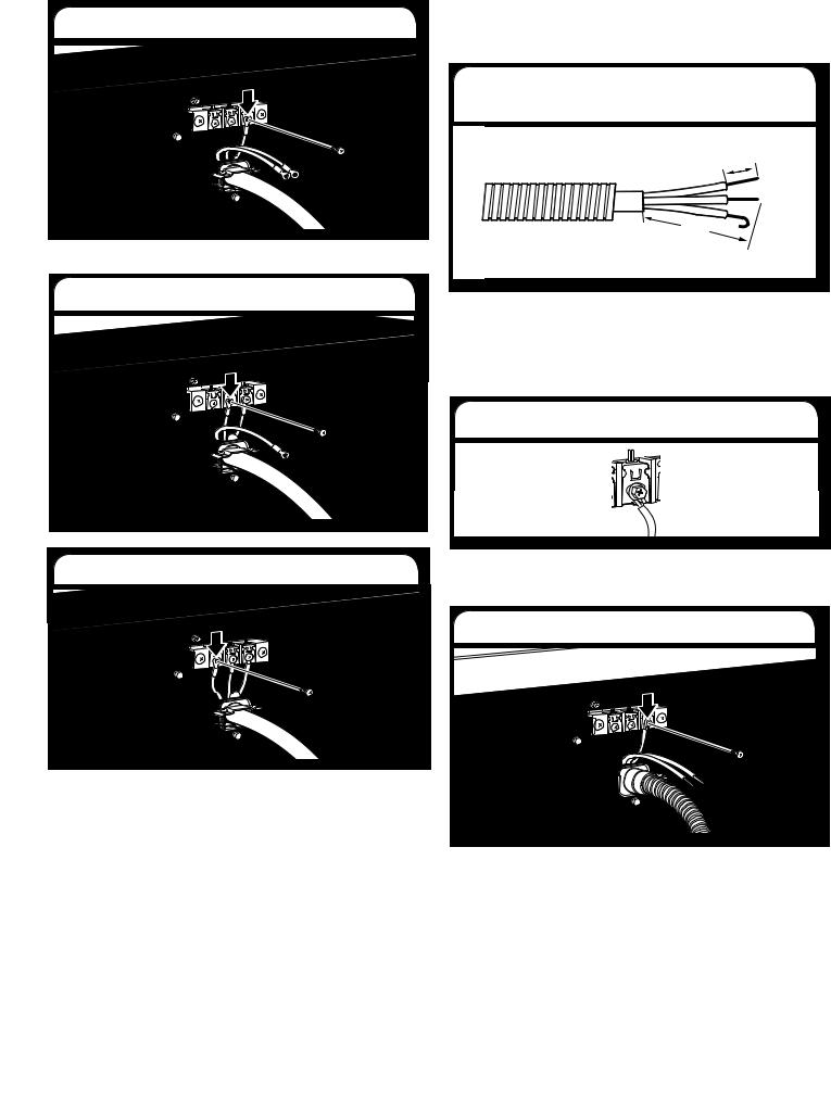
Direct Wire Connection
Use where local codes permit connecting cabinet-ground conductor to neutral wire.
3. Prepare your 3-wire cable for direct connection
1" |
|
(25 |
mm) |
|
|
3½" |
|
(89 |
mm) |
|
|
Direct wire cable must have 5 ft (1.52 m) of extra length so dryer may be moved if needed.
Strip 31/2" (89 mm) of outer covering from end of cable. Strip insulation back 1" (25 mm). If using 3-wire cable with ground wire, cut bare wire even with outer covering. Shape wire ends into hooks.
4. Connect wires to terminal block
To connect wires to terminal block, place hooked end of wire under terminal block screw, facing to the right, squeeze hooked end together and tighten screw.
5. Connect neutral wire
Place hooked end of neutral wire (blue) of power supply cable under the right screw of terminal block (hook facing right). Squeeze hooked end together. Tighten screw.
9
6. Connect ground wire |
VENTING |
VENTING REQUIREMENTS
Place hooked end of ground wire power supply cable under the center terminal block screw (hook facing right). Squeeze hooked end together and tighten screw.
7. Connect active wire
Place hooked end of the active wire (brown) power supply cable under the left terminal block screw (hook facing right). Squeeze hooked end together. Tighten screw and strain relief screw.
Finally, reinsert tab of terminal block cover into slot of dryer rear panel. Secure cover with hold-down screw. Now, go to “Venting Requirements”.
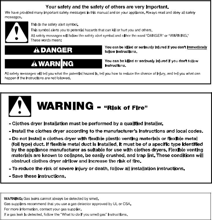
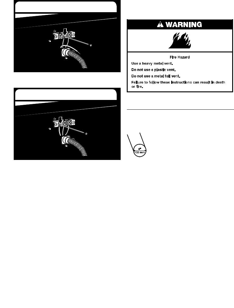
WARNING: To reduce the risk of fire, this dryer MUST BE EXHAUSTED OUTDOORS.
IMPORTANT: Observe all governing codes and ordinances.
Dryer exhaust must not be connected into any gas vent, chimney, wall, ceiling, attic, crawlspace, or a concealed space of a building. Only rigid or flexible metal vent shall be used for exhausting.
■■ Only a 4" (102 mm) heavy metal exhaust vent and clamps may be used.
■■ Do not use plastic or metal foil vent.
Rigid metal vent:
■■ Recommended for best drying performance and to avoid crushing and kinking.
Flexible metal vent: (Acceptable only if accessible to clean) ■■ Must be fully extended and supported in final dryer location.
■■ Remove excess to avoid sagging and kinking that may result in reduced airflow and poor performance.
■■ Do not install in enclosed walls, ceilings, or floors. ■■ The total length should not exceed 73/4 ft (2.4 m).
NOTE: If using an existing vent system, clean lint from entire length of the system and make sure exhaust hood is not plugged with lint. Replace plastic or metal foil vents with rigid metal or flexible metal vents. Review Vent system chart and if necessary, modify existing vent system to achieve best drying performance.
10
Exhaust hoods:
■■ Must be at least 12" (305 mm) from ground or any object that may obstruct exhaust (such as flowers, rocks, bushes, or snow).
B
PLAN VENT SYSTEM
Recommended exhaust installations
Typical installations vent the dryer from the rear of the dryer. Other installations are possible.
|
4" |
|
A |
(102 mm) |
|
|
||
4" |
2½" |
|
(102 mm) |
||
(64 mm) |
||
|
||
4" |
|
|
(102 mm) |
|
|
Recommended styles: |
Acceptable styles: |
|
A. Louvered hood |
C. Angled hood |
|
B. Box hood |
|
Elbows:
■■ 45° elbows provide better airflow than 90° elbows.
A
A.Dryer
B.Elbow
C.Wall
D.Exhaust hood
B
 C
C
 D
D
E |
F |
G |
B
H
E.Clamps
F.Rigid metal or flexible metal vent
G.Vent length necessary to connect elbows
H.Exhaust outlet
Good |
Better |
Clamps:
■■ Use clamps to seal all joints.
■■ Exhaust vent must not be connected or secured with screws or other fastening devices that extend into interior of duct and catch lint. Do not use duct tape.
Standard exhaust installation with rigid or flexible metal vent
11

Alternate installations for close clearances
Venting systems come in many varieties. Select the type best for your installation. Two close-clearance installations are shown. Refer to the manufacturer’s instructions.
Over-The-Top installation (also available with one offset elbow)
Periscope installation
NOTE: The following kits for close clearance alternate installations are available for purchase. To order, please contact the dealer from whom you purchased your dryer or an authorized service company.
■■ Over-the-Top Installation:
Part Number 4396028
■■ Periscope Installation (For use with dryer vent to wall vent mismatch):
Part Number 4396037 - 0" (0 mm) to 18" (457.2 mm) mismatch
Part Number 4396011 - 18" (457.2 mm) to 29" (736.6 mm) mismatch
Part Number 4396014 - 29" (736.6 mm) to 50" (1270 mm) mismatch
Determine vent path:
■■ Select route that will provide straightest and most direct path outdoors.
■■ Plan installation to use fewest number of elbows and turns.
■■ When using elbows or making turns, allow as much room as possible.
■■ Bend vent gradually to avoid kinking. ■■ Use as few 90° turns as possible.
Determine vent length and elbows needed for best drying performance:
■■ Use following Vent System Chart to determine type of vent material and hood combinations acceptable to use.
NOTE: Do not use vent runs longer than those specified in Vent System Chart. Exhaust systems longer than those specified will:
■■ Shorten life of dryer.
■■ Reduce performance, resulting in longer drying times and increased energy usage.
The Vent System Chart provides venting requirements that will help achieve best drying performance.
Vent System Chart
|
Number of |
Type |
Box/louvered |
Angled |
|
|
90° turns |
of vent |
hoods |
hoods |
|
|
or elbows |
|
|
|
|
|
0 |
Rigid metal |
64 ft (20 m) |
58 ft (17.7 m) |
|
|
|
|
|
|
|
|
1 |
Rigid metal |
54 ft (16.5 m) |
48 ft (14.6 m) |
|
|
|
|
|
|
|
|
2 |
Rigid metal |
44 ft (13.4 m) |
38 ft (11.6 m) |
|
|
|
|
|
|
|
|
3 |
Rigid metal |
35 ft (10.7 m) |
29 ft (8.8 m) |
|
|
|
|
|
|
|
|
4 |
Rigid metal |
27 ft (8.2 m) |
21 ft (6.4 m) |
|
|
|
|
|
|
|
|
|
|
|
|
|
INSTALL VENT SYSTEM
1. Install exhaust hood
12" min.
(305 mm)
12" min.
 (305 mm)
Install exhaust hood and use caulking compound to seal exterior wall opening around exhaust hood.
12

2. Connect vent to exhaust hood
Vent must fit over the exhaust hood. Secure vent to exhaust hood with 4" (102 mm) clamp. Run vent to dryer location using straightest path possible. Avoid 90° turns. Use clamps to seal all joints. Do not use duct tape, screws, or other fastening devices that extend into interior of vent to secure vent, because they can catch lint.
MAKE GAS CONNECTION
1. Connect gas supply to dryer
Flared |
Non-flared |
maleA fitting |
B |
male fitting |
Remove red cap from gas pipe. Using a wrench to tighten, connect gas supply to dryer. Use pipe-joint compound
on threads of all non-flared male fittings. If flexible metal tubing is used, be sure there are no kinks.
NOTE: For LP gas connections, you must use pipe-joint compound resistant to action of LP gas. Do not use TEFLON®† tape.
2. Plan pipe fitting connection
A
B
A.3/8" flexible gas connector
B.3/8" dryer pipe
C.3/8" to ISO thread adapter fitting.
C D E
D.3/8" to 3/8" pipe elbow
E.3/8" pipe-to-flare adapter fitting
A combination of pipe fittings must be used to connect dryer to existing gas line. A recommended connection is shown. Your connection may be different, according to supply line type, size, and location.
†®TEFLON is a registered trademark of E.I. Dupont De Nemours and Company.
3. Open shut-off valve
Closed Avalve
 OpenB valve
Open shut-off valve in supply line; valve is open when handle is parallel to gas pipe. Then, test all connections by brushing on an approved noncorrosive leak-detection solution.
Bubbles will show a leak. Correct any leaks found.
CONNECT VENT
1. Connect vent to exhaust outlet
Using a 4" (102 mm) clamp, connect vent to exhaust outlet in dryer. If connecting to existing vent, make sure vent is clean. Dryer vent must fit over dryer exhaust outlet and inside exhaust hood. Check that vent is secured to exhaust hood with a 4" (102 mm) clamp.
2. Move dryer to final location
Move dryer to final location. Avoid crushing or kinking vent. After dryer is in place, remove corner posts and cardboard from under the dryer.
13
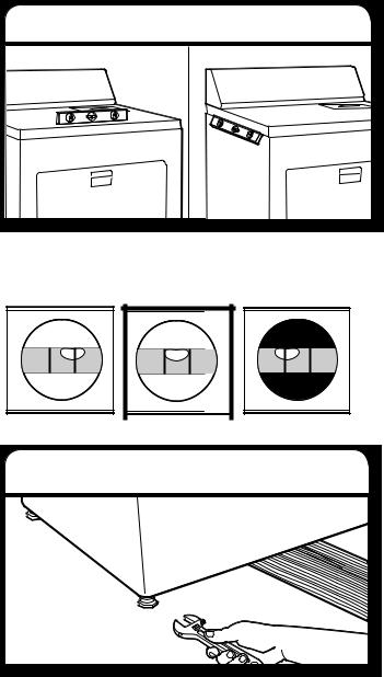
LEVEL DRYER
1. Level Dryer
Check levelness of dryer from side to side. Repeat from front to back.
NOTE: The dryer must be level for the moisture sensing system to operate correctly.
Not Level |
LEVEL |
Not Level |
2. Tighten and adjust leveling legs
If dryer is not level, prop up using a wood block, use wrench to adjust legs up or down, and check again for levelness. Once legs are level, make sure all four legs are snug against the ground before tightening them.
COMPLETE INSTALLATION CHECKLIST
qCheck that all parts are now installed. If there is an extra part, go back through steps to see what was skipped.
qCheck that you have all of your tools.
qDispose of/recycle all packaging materials.
qCheck dryer’s final location. Be sure vent is not crushed or kinked.
qFor power supply cord installation, plug into an outlet. For direct wire installation, turn on power.
qCheck that dryer is level. See “Level Dryer”.
qRemove film on console and any tape remaining on dryer.
qWipe dryer drum interior thoroughly with a damp cloth to remove any dust.
qRead “Dryer Use” in your Use and Care Guide.
qSet the dryer on a full heat cycle (not an air cycle) for
20 minutes and start the dryer. (If you have a gas dryer, it is equipped with an electronic ignition system for the burner which is fully automatic; no action is needed by the user (there is no pilot light).
If the dryer will not start, check the following:
■■ Controls are set in a running or “On” position. ■■ Start button has been pushed firmly.
■■ Dryer is plugged into an outlet and/or electrical supply is on.
■■ Household fuse is intact and tight, or circuit breaker has not tripped.
■■ Dryer door is closed.
qWhen the dryer has been running for 5 minutes, open the dryer door and feel for heat. If you feel heat, cancel cycle and close the door.
If you do not feel heat, turn off dryer, and check the following:
■■ There may be 2 household fuses or circuit breakers for the dryer. Check that both fuses are intact and tight, or that both circuit breakers have not tripped. If there is still no heat, contact a qualified technician.
NOTE: You may notice an odor when the dryer is first heated. This odor is common when the heating element is first used. The odor will go away.
14
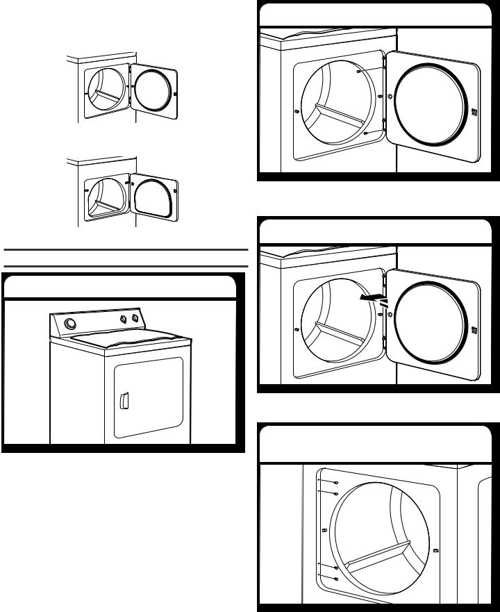
REVERSE DOOR SWING (OPTIONAL)
If your door is the 29" Large Side-Swing Door, follow steps 1-6.
If your door is the 29" Super Wide Side-Swing Door, follow steps 1-13 on page 16.
NOTE: Magnetized screw driver is helpful.
Large Side-Swing Door
1. Place towel on dryer
Place towel on top of dryer to avoid damaging the surface.
2. Remove bottom screws
Open dryer door. Remove bottom screws from dryer cabinet side of hinges. Loosen (do not remove) top screws from dryer cabinet side of hinges.
3. Lift door off top screws
Lift door until top screws in cabinet are in large part of hinge slot. Pull door forward off screws. Set door on top of dryer. Remove top screws from dryer cabinet.
4. Remove and transfer hinge hole plugs
Use a small, flat-blade screwdriver to gently remove 4 hinge hole plugs on left side of dryer cabinet. Insert plugs into hinge holes on opposite side of dryer cabinet.
15

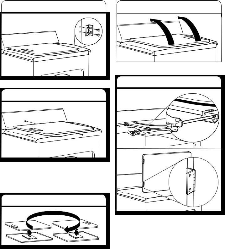
5. Insert screws in hinge holes on dryer cabinet
NOTE: Two people maybe needed to reinstall door.
Insert screws into bottom holes on left side of dryer cabinet. Tighten screws halfway. Position door so large end of door hinge slot is over screws. Slide door up so screws are in bottom of slots. Tighten screws. Insert and tighten top screws in hinges.
6. Check door strike alignment
Close door and check that door strike aligns with door catch. If needed, slide door catch left or right within slot to adjust alignment.
Super Wide Side-Swing Door
1. Place towel on dryer
Place towel on top of dryer to avoid damaging the surface.
2. Remove bottom screws
Open dryer door. Remove bottom screws from dryer cabinet side of hinges. Loosen (do not remove) top screws from dryer cabinet side of hinges.
3. Lift door off top screws
Lift door until top screws in dryer cabinet are in large part of hinge slot. Pull door forward off screws. Set door (handle side up) on top of dryer. Remove top screws from dryer cabinet.
16
4. Remove screws from hinges |
|
7. Flip door over |
|
|
|
|
|
|
|
|
|
Remove screws attaching hinges to door.
5. Remove screws from door
Remove screws at top, bottom, and side of door (4 screws). Keep door screws separate from hinge screws as they are diferent sizes. Holding door over towel on dryer, grasp sides of outer door and lift to separate it from inner door.
NOTE: Do not pry apart with putty knife or screwdriver. Do not pull on door seal or plastic door catches.
6. Rotate outer door
Take outer door and rotate in 180º and set it back down on inner door. Be certain to keep cardboard spacer centered between doors. Reattach outer door panel to inner door panel so handle is on the side where hinges were just removed. Insert 4 door screws.
Flip door over so handle side is down.
8. Attach door hinges
Reattach door hinges to dryer door so that the larger hole is at the bottom of the hinge.
17

9. Remove door strike |
12. Remove door strike plug |
Remove door strike from dryer cabinet and set aside.
10. Remove and transfer hinge hole plugs
Use a small, flat-blade screwdriver to gently remove 4 hinge hole plugs on left side of dryer cabinet. Transfer plugs into hinge holes on opposite side of dryer cabinet.
11. Insert screws in hinge holes on dryer cabinet
NOTE: Two people maybe needed to reinstall door.
Insert screws into the bottom holes on left side of dryer cabinet. Tighten screws halfway. Position door so large end of door hinge slot is over screws. Slide door up so screws are in bottom of slots. Tighten screws. Insert and tighten top screws in hinges.
Remove door strike plug. Insert the door strike removed in Step 9 into hole and secure with screw. Insert door strike plug into original door strike hole and secure with screw.
13. Check door strike alignment
Close door and check that door strike aligns with door catch. If it is needed, slide door catch left or right within slot to adjust alignment.
Troubleshooting
See the Use and Care Guide to possibly avoid the cost of a service call.
18

SECURITE DU SECHE-LINGE
19
EXIGENCES D’INSTALLATION
OUTILLAGE ET PIECES
Rassembler les outils et pièces nécessaires avant de commencer l’installation. Lire et suivre les instructions fournies avec les outils indiqués ici.
Outils nécessaires pour toutes les installations :
Tournevis à lame plate |
Tournevis Phillips no 2 |
Clé à molette avec ouverture jusqu’à 25 mm (1") ou clé à douille à tête hexagonale
Niveau
Pistolet à calfeutrage et composé de calfeutrage (pour l’installation d’un nouveau circuit d’évacuation)
Clapets d’évacuation
Cisaille de ferblantier |
Pince à dénuder les fils |
(pour l’installation d’un |
(pour les installations à |
nouveau conduit) |
raccordement direct) |
Mètre ruban |
Couteau utilitaire |
20
Outils nécessaires aux installations au gaz :
Clé à tuyau réglable qui |
Composé d’étanchéité |
s’ouvre jusqu’à 204 mm |
des raccords filetés – |
(8") ou 254 mm (10") |
résistant au gaz propane |
Pièces fournies (tous les modèles) :
Pieds de nivellement (4)
Le sachet de pièces se trouve dans le tambour du sèche-linge. Vérifier que toutes les pièces sont présentes.
Pièces nécessaires :
Consulter les codes locaux. Vérifier l’alimentation électrique et le circuit d’évacuation existants. Voir “Spécifications électriques” et “Exigences concernant l’évacuation” avant d’acheter les pièces.
En cas d’utilisation d’un câble d’alimentation électrique :
Utiliser un ensemble de câble d’alimentation électrique homologué UL marqué compatible avec les sèche-linge. L’ensemble doit contenir :
■■ Un câble d’alimentation électrique homologué UL de 30 ampères, 230 volts minimum. Le cordon doit être de type SRD ou SRDT et mesurer au moins 1,22 m (4 ft) de long. Les fils raccordés au sèche-linge doivent se terminer par des cosses rondes ou à fourche à pointes relevées.
■■ Un serre-câble (homologation UL).
Pour une installation au gaz :
Consulter la réglementation locale et le fournisseur de gaz, et lire les exigences relatives au branchement électrique, au gaz et à l’évacuation avant d’acheter des pièces.
La conduite d’alimentation en gaz doit comprendre : ■■ Un robinet d’arrêt
La conduite rigide d’alimentation en gaz doit respecter les exigences suivantes :
■■ Un tuyau de 12,5 mm (1/2") de diamètre intérieur minimum
La conduite flexible d’alimentation en gaz doit respecter les exigences suivantes :
■■ Conduite flexible homologuée de 10 mm (3/8") de diamètre intérieur minimum
Conversion au gaz butane/propane :
Un ensemble de conversion de gaz est disponible à l’achat chez votre marchand. Toutes les instructions sont fournies dans cet ensemble. Un technicien qualifié doit effectuer la conversion.
Des pièces supplémentaires seront peut-être nécessaires, selon l’installation. Consulter les codes locaux. Vérifier la ventilation et les alimentations en gaz et électrique existantes. Voir “Exigences concernant l’installation électrique”, “Exigences concernant l’alimentation en gaz” et “Exigences concernant l’évacuation” avant d’acheter les pièces.
EXIGENCES D’EMPLACEMENT
On a besoin de :
■■ Un emplacement permettant une évacuation appropriée. Voir “Exigences concernant l’évacuation”.
■■ Un circuit séparé de 30 ampères.
■■ Si on utilise un cordon d’alimentation, une prise électrique avec liaison à la terre située à moins de 610 mm (2 ft) de l’un des côtés du sèche-linge. Voir “Spécifications électriques”.
■■ Un plancher robuste capable de supporter le poids du sèchelinge (sèche-linge et charge) de 90,7 kg (200 lb). Il faut aussi prendre en compte le poids combiné d’un appareil ménager voisin.
■■ Un plancher de niveau ayant une pente maximale de 25 mm (1") sous l’ensemble du sèche-linge. Si la pente est supérieure à 25 mm (1"), installer un ensemble de pieds d’extension pour sèche-linge, pièce n° 279810. Si le sèche-linge n’est pas d’aplomb, le linge peut ne pas culbuter convenablement, et les programmes automatiques commandés par détecteur peuvent ne pas fonctionner correctement.
Ne pas faire fonctionner le sèche-linge à une température inférieure à 7°C (45°F). A des températures inférieures, le sèche-linge risque de ne plus s’arrêter à la fin d’un programme automatique. Les temps de séchage risquent alors d’augmenter.
Le sèche-linge ne doit pas être installé ou remisé dans un endroit où il sera exposé à l’eau et/ou aux intempéries.
Vérifier les règlements locaux. Certains codes limitent ou n’autorisent pas l’installation des sèche-linge dans un garage, un placard ou une chambre à coucher. Communiquer avec l’inspecteur des bâtiments local.
Espacements d’installation :
L’emplacement doit être assez grand pour permettre d’ouvrir complètement la porte du sèche-linge.
21
Dimensions du sèche-linge
|
387 mm |
|
|
578 mm |
1102 mm |
(15¼") |
1102 mm |
(22¾") |
|
(433/8") |
|
|
(433/8") |
|
*660 mm |
|
|
705 mm |
|
(26") |
737 mm |
|
(*27¾") |
737 mm |
|
|
|
||
|
(29") |
|
|
(29") |
|
A |
|
|
B |
|
578 mm |
|
|
|
|
(22¾") |
1102 mm |
|
|
1102 mm |
|
|
|
|
|
|
(433/8") |
|
|
(433/8") |
|
|
349 mm |
|
|
|
|
|
|
|
|
|
|
(13¾") |
705 mm |
|
|
705 mm |
|
(*27¾") |
737 mm |
|
(*27¾") |
737 mm |
|
|
|
||
|
(29") |
|
|
(29") |
|
C |
|
|
D |
A.Porte à pivotement latéral à petite ouverture
B.Porte à pivotement latéral à grande ouverture
C.Porte à pivotement latéral à large ouverture
D.Porte rabattable à large ouverture
*La plupart des installations requièrent un espace minimum de 127 mm (5") derrière le sèche-linge pour le conduit d’évacuation avec coude. Voir “Exigences concernant l’évacuation”.
Dégagement minimal pour une installation dans un encastrement ou un placard
Les dimensions correspondent à l’espacement minimum permis.
■■ Prévoir davantage d’espace pour faciliter l’installation et l’entretien.
■■ Un espace supplémentaire peut être requis pour les moulures de porte et de plancher et pour les plinthes.
■■ Un espace supplémentaire de 25 mm (1") doit être envisagé de chaque côté du sèche-linge afin de réduire le transfert de bruit.
■■ Pour installation dans un placard avec porte, on doit prévoir des ouvertures minimums d’entrée d’air en haut et en bas de la porte. Les portes à claire-voie offrant des ouvertures équivalentes de passage de l’air sont acceptables.
■■ Il faut aussi prendre en compte l’espace requis entre les appareils voisins.
356 mm  (14"max.)
76 mm |
|
(3") |
310 cm2 |
457 mm |
(48 in.2) |
|
|
(18") |
|
|
155 cm2 |
|
102 mm |
(24 in.2) |
|
76 mm |
||
(4") |
||
(3") |
||
|
 25 mm 0 mm (1")

 (0")
(0")
A.Encastrement
B.Vue latérale - placard ou endroit exigu
C.Porte du placard avec orifices d’entrée d’air
*Espace supplémentaire recommandé
SPECIFICATIONS ELECTRIQUES
C’est à l’utilisateur qu’incombe la responsabilité de :
■■ Contacter un électricien qualifié.
■■ Veiller à ce que le branchement électrique soit correctement effectué et conforme aux prescriptions de tous les codes et règlements locaux en vigueur.
■■ Fournir une alimentation de 230 VCA, 60 Hz monophasée à 3 fils, sur un circuit séparé de 30 ampères (15 ou 20 ampères pour les sèche-linge à gaz) protégé par fusible aux deux
extrémités de la ligne. On recommande d’utiliser un fusible ou un disjoncteur temporisé. On recommande également que cet appareil soit alimenté par un circuit indépendant. Ne pas avoir de fusible dans le circuit neutre ou de liaison à la terre.
■■ Ne pas utiliser de câble de rallonge.
■■ Si les codes le permettent et si l’on utilise un conducteur distinct de liaison à la terre, il est recommandé qu’un électricien qualifié vérifie la qualité de la liaison à la terre.
Raccordement électrique
Pour installer le sèche-linge de façon appropriée, il faut déterminer le type de raccordement électrique à utiliser et suivre les présentes instructions.
En cas d’utilisation d’un câble d’alimentation électrique :
Utiliser un ensemble de câble d’alimentation électrique homologué UL marqué compatible avec les sèche-linge. L’ensemble doit contenir :
■■ Un câble d’alimentation électrique homologué UL de 30 ampères, 230 volts minimum. Le cordon doit être de type SRD ou SRDT et mesurer au moins 1,22 m (4 ft) de long. Les fils raccordés au sèche-linge doivent se terminer par des cosses rondes ou à fourche à pointes relevées.
■■ Un serre-câble (homologation UL).
22
Raccordement direct :
Le câble doit correspondre à l’alimentation électrique et présenter les caractéristiques suivantes :
■■ Un câble en cuivre à gaine non métallique ou blindé souple (avec fil de liaison à la terre), avec conduit métallique souple. Tous les fils sous tension doivent être isolés.
■■ Fil en cuivre plein de calibre 10 (ne pas utiliser d’aluminium). ■■ Longueur d’au moins 1,52 m (5 ft).
INSTRUCTIONS DE LIAISON À LA TERRE
■ Pour un sèche-linge relié à la terre et connecté par un cordon :
Ce sèche-linge doit être relié à la terre. En cas de mauvais fonctionnement ou de panne, la liaison à la terre réduira le risque de choc électrique en offrant au courant électrique un acheminement d’évacuation de moindre résistance. La •che doit être branchée sur une prise appropriée qui est bien installée et reliée à la terre conformément à tous les codes et règlements locaux.
AVERTISSEMENT : Le raccordement incorrect de cet appareil au conducteur de liaison à la terre peut susciter un risque de choc électrique. En cas de doute quant à la qualité de liaison à la terre du sèche-linge, consulter un électricien ou un technicien ou un personnel quali•é. Ne pas modi•er la •che de branchement fournie avec le sèche-linge; si la •che ne correspond pas à la con•guration de la prise de courant, demander à un électricien quali•é d’installer une prise de courant appropriée.
CONSERVEZ CES INSTRUCTIONS
EXIGENCES CONCERNANT L’ALIMENTATION EN GAZ
RESPECTER LES DISPOSITIONS DE TOUS LES CODES ET REGLEMENTS EN VIGUEUR.
Alimentation en gaz :
Vérifier que le sèche-linge est équipé du brûleur approprié correspondant au type de gaz utilisé. Les informations concernant le brûleur se trouvent sur la plaque signalétique située sur la paroi interne de la porte du sèche-linge. Si l’information ne correspond pas au type de gaz disponible, consulter votre revendeur.
Gaz naturel :
Ce sèche-linge est configuré en usine pour l’utilisation au GAZ NATUREL (G20) et aucun réglage supplémentaire n’est nécessaire lors de l’installation.
Gaz butane/propane :
Ce sèche-linge est également homologué pour une utilisation avec des gaz de pétrole liquéfiés (propane ou butane) avec la conversion appropriée. Ne pas entreprendre de convertir l’appareil pour une utilisation avec un gaz différent de celui indiqué sur la plaque signalétique sans d’abord consulter le fournisseur de gaz.
La conversion doit être effectuée par un technicien qualifié.
Des ensembles de conversion de gaz sont disponibles à l’achat chez votre revendeur. Toutes les instructions sont fournies dans cet ensemble.
Exigences concernant la conduite d’alimentation
Installer une conduite rigide d’alimentation en gaz à l’emplacement du sèche-linge. Le diamètre interne minimal de la conduite doit être de 12,5 mm (1/2"). Lorsque les codes locaux et votre fournisseur de gaz l’autorisent, une conduite rigide de diamètre intérieur de 10 mm (3/8") peut être utilisée pour des longueurs inférieures à 6,1 m (20 ft). Un produit d’étanchéité résistant à l’action du gaz propane/butane doit être utilisé pour les joints des conduites.
23
 Loading...