


4GWTW4740
Whirlpool 4GWTW4740, 4GWTW4800, 4GMVWCl00, 4GMVWC300, 4GWTW5550 Installation Instructions Manual
...
WASHER INSTALLATION INSTRUCTIONS
INSTRUCTIONS POUR UINSTALLATION DU LAVE-LINGE
INSTRUCCIONES DE INSTALACION DE LA LAVADORA
Table of Contents
WASHER SAFETY ...................................................................... 2
iNSTALLATiON REQUIREMENTS ............................................. 2
Tools and Parts ................................................................... 2
Location Requirements ..................................................... 3
Drain System ...................................................................... 3
Electrical Requirements .................................................... 4
Table des mati_res
SLeCURIT# DU LAVE-LINGE .................................................... 10
EXIGENCES D'INSTALLATION ............................................... 10
Outillage et pi_ces ........................................................... 10
Exigences d'emplacement .............................................. 11
Syst_me de vidange ......................................................... 11
Sp6cifications _lectriques ............................................... 12
iNSTALLATiON iNSTRUCTiONS ............................................... 5
Connect Drain Hose ........................................................... 6
Connect inlet Hoses ........................................................... 6
Level Washer ...................................................................... 8
Power Cord InstaJlation ..................................................... 9
Complete Installation Checklist ........................................ 9
iNSTRUCTiONS D'INSTALLATION ......................................... 13
Raccordement du tuyau de vidange ............................... 14
Raccordement des tuyau× d'arriv_e d'eau .................... 15
Etablissement de I'aplomb du lave=linge ....................... 16
installation du cordon d'alimentation ............................. 17
Liste de v_rification pour I'ach_vement
de I'installation ................................................................. 18
SEGURIDAD DE LA LAVADORA ............................................. 19
REQUISITOS DE INSTALACION ............................................. 19
Herramientas y piezas ..................................................... 19
Requisitos de ubicaci6n .................................................. 20
Sistema de desagiJe ......................................................... 20
Requisitos el6ctricos ....................................................... 21
W10549313A
INSTRUCCIONES DE INSTALACION ..................................... 22
Cone×i6n de la manguera de desagQe ........................... 23
Conexi6n de las mangueras de entrada ........................ 24
Nivelaci6n de la lavadora ................................................ 25
Instalaci6n del cable el_ctrico ........................................ 26
Lista de control de la instalaci6n terminada ................. 27
4GWTW4740
4GWTW4800
4GMVWCl00
4GMVWC300
4GWTW5550
4GWTW4950
4GMVWX500
4GMVWC400
4GNTW4400
4GNTW4600
4GATW4900
WASHER SAFETY
Your safety and the safety of others are very important.
We have provided many important safety messages in this manual and on your appliance. Always read and obey all safety
messages.
This is the safety alert symbol.
This symbol alerts you to potential hazards that can kill or hurt you and others.
All safety messages will follow the safety alert symbol and either the word "DANGER" or "WARNING."
These words mean:
You can be killed or seriously injured if you don't immediately
follow instructions.
You can be killed or seriously injured if you don't follow
instructions.
All safety messages will tell you what the potential hazard is, tell you how to reduce the chance of injury, and tell you what can
happen if the instructions are not followed.
INSTALLATION REQUIREMENTS
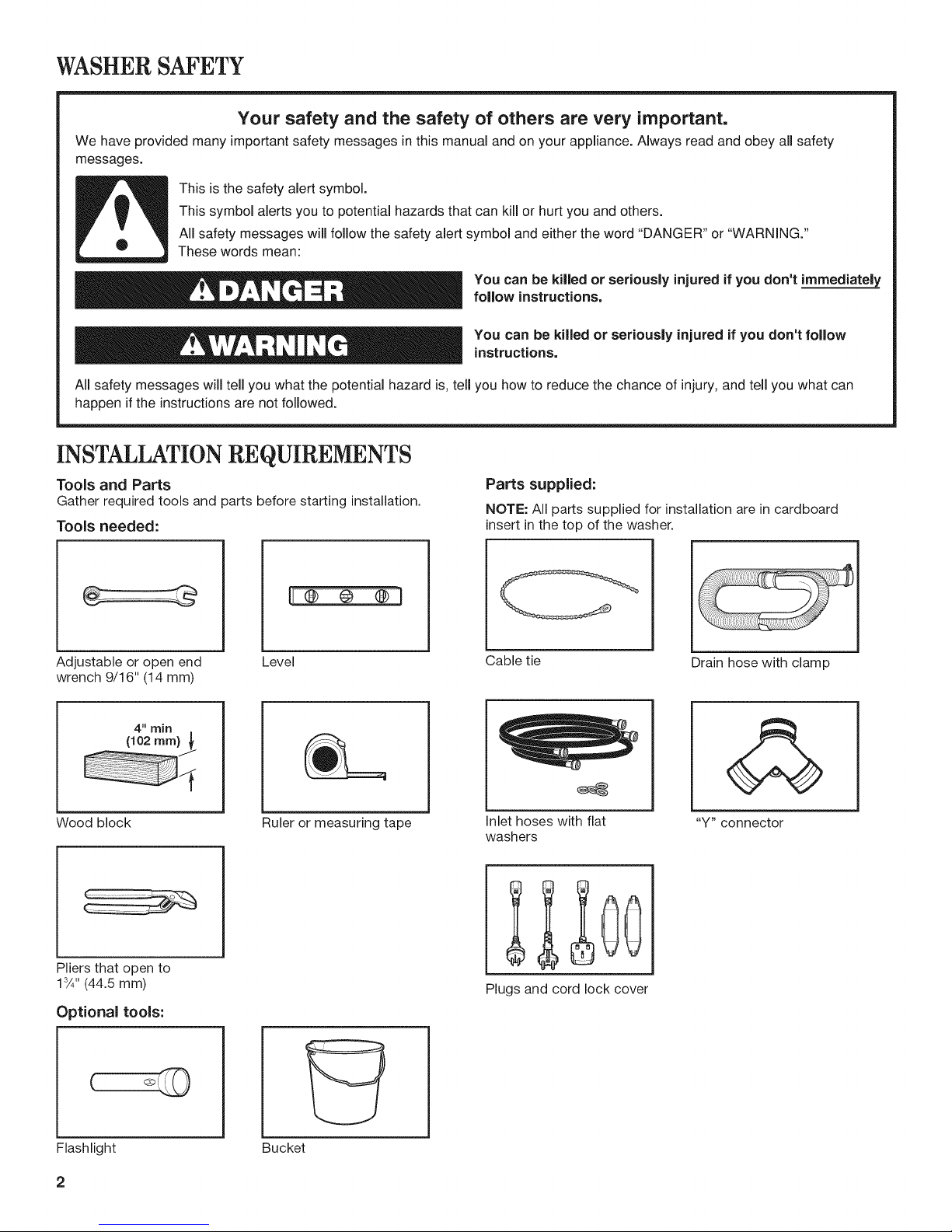
Tools and Parts
Gather required tools and parts before starting installation.
Tools needed:
Parts supplied:
NOTE: All parts supplied for installation are in cardboard
insert in the top of the washer.
Adjustable or open end
wrench 9/16" (14 mm)
4" rain
(102 mm)_
Wood block
Pliers that open to
13A'' (44.5 mm)
Optional tools:
Level Cable tie
Ruler or measuring tape
Net hoses with flat
washers
£1 c0
Plugs and cord lock cover
Drain hose with clamp
"Y" connector
Flashlight
2
Bucket
Alternate parts: (Not supplied with washer)
Your installation may require additional parts. To order, please
contact the dealer from whom you purchased your washer or an
authorized service company.
If you have:
Overhead sewer
You will need:
Standard 20 gal. (76 L) 39" (990 mm)
tall drain tub or utility sink, sump
pump and connectors (available from
local plumbing suppliers)
1" (25 mm) standpipe
2" (51 mm) diameter to 1" (25 mm)
diameter Standpipe Adapter
Part Number 3363920
Connector Kit Part Number 285835
Drain hose too short Extension Drain Hose Part
Number 285863
Connector Kit Part Number 285835
Lint clogged drain
Drain Protector Part Number 367031
Connector Kit Part Number 285835
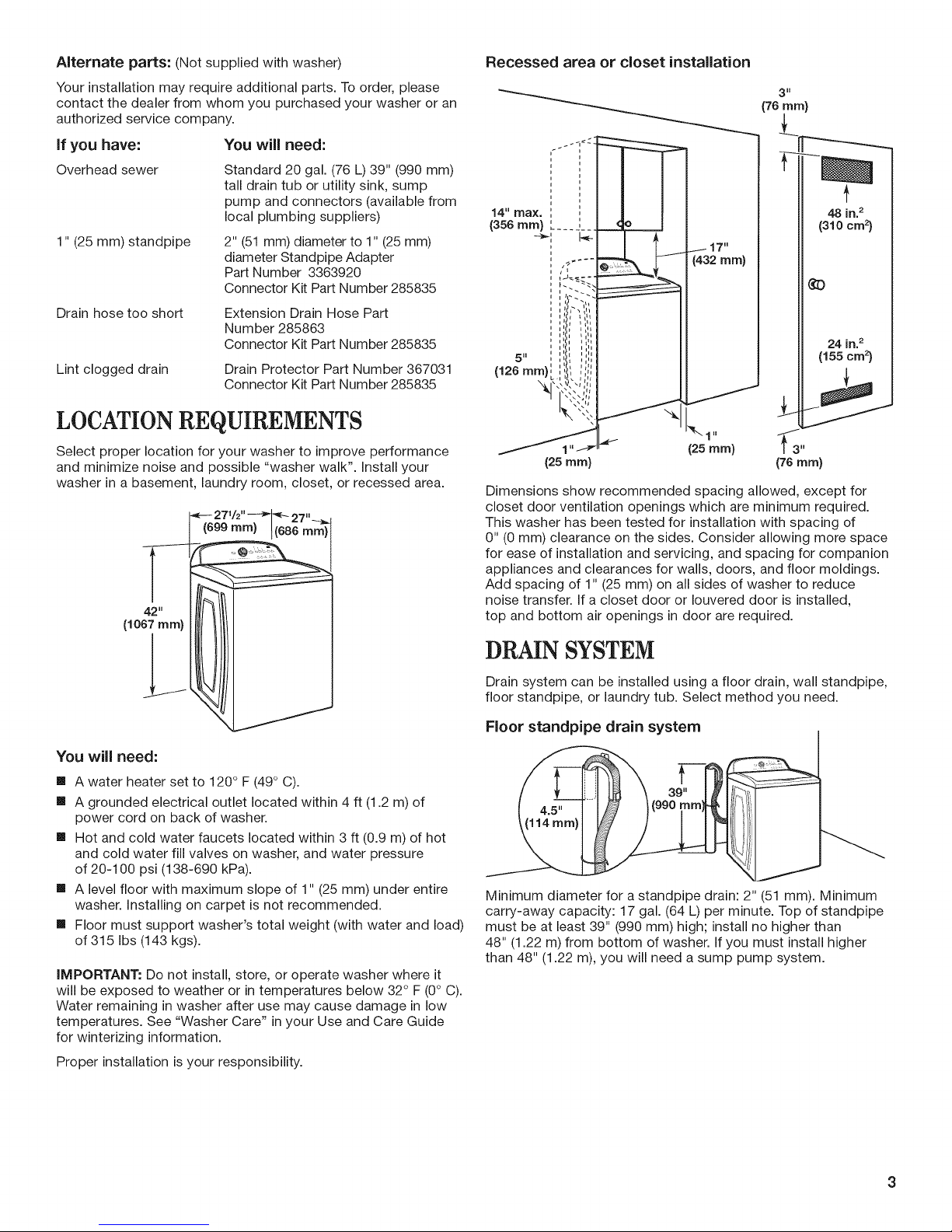
LOCATIONREQUIREMENTS
Select proper location for your washer to improve performance
and minimize noise and possible "washer walk". Install your
washer in a basement, laundry room, closet, or recessed area.
42"
(1067mm)
Recessed area or closet installation
(76 ram)
u
14 =.max. i
(356 ram) .... j__.
117"
(432 ram)
48 in.2
(310 cm2)
¢3
,L,,:,i
24 in.2
5H _ n_ll
(126 m , ,,,,
I
\ \t iq
\%q
Jlq
(155 cm2)
(25 ram)
(25 ram)
(76 ram)
Dimensions show recommended spacing allowed, except for
closet door ventilation openings which are minimum required.
This washer has been tested for installation with spacing of
0" (0 mm) clearance on the sides. Consider allowing more space
for ease of installation and servicing, and spacing for companion
appliances and clearances for walls, doors, and floor moldings.
Add spacing of 1" (25 mm) on all sides of washer to reduce
noise transfer. If a closet door or Iouvered door is installed,
top and bottom air openings in door are required.
DRAIN SYSTEM
You will need:
[] A water heater set to 120 ° F (49° C).
[] A grounded electrical outlet located within 4 ft (1.2 m) of
power cord on back of washer.
[] Hot and cold water faucets located within 3 ft (0.9 m) of hot
and cold water fill valves on washer, and water pressure
of 20-100 psi (138-690 kPa).
[] A level floor with maximum slope of 1" (25 mm) under entire
washer. Installing on carpet is not recommended.
[] Floor must support washer's total weight (with water and load)
of 315 Ibs (143 kgs).
IMPORTANT: Do not install, store, or operate washer where it
will be exposed to weather or in temperatures below 32° F (0° C).
Water remaining in washer after use may cause damage in low
temperatures. See "Washer Care" in your Use and Care Guide
for winterizing information.
Proper installation is your responsibility.
Drain system can be installed using a floor drain, wall standpipe,
floor standpipe, or laundry tub. Select method you need.
Floor standpipe drain system
Minimum diameter for a standpipe drain: 2" (51 mm). Minimum
carry-away capacity: 17 gal. (64 L) per minute. Top of standpipe
must be at least 39" (990 mm) high; install no higher than
48" (1.22 m) from bottom of washer. If you must install higher
than 48" (1.22 m), you will need a sump pump system.

Wall standpipe drain system
See requirements for floor standpipe drain system.
Floor drain system
(
ELECTRICAL REQUIREMENTS
Electrical Shock Hazard
Plug into a grounded 3 prong outlet.
Do not remove ground prong.
Do not use an adapter.
Do not use an extension cord.
Failure to follow these instructions can result in death,
fire, or electrical shock.
Floor drain system requires a Siphon Break Kit (Part Number
285834), 2 Connector Kits (Part Number 285835), and an
Extension Drain Hose (Part Number 285863) that may be
purchased separately. To order, please contact the dealer from
whom you purchased your washer or an authorized service
company. Minimum siphon break: 28" (710 mm) from bottom
of washer. (Additional hoses may be needed.)
Laundry tub drain system
Minimum capacity: 20 gal. (76 L). Top of laundry tub must be at
least 39" (990 mm) above floor; install no higher than 48" (1.22 m)
from bottom of washer.
iMPORTANT: To avoid siphoning, no more than 4.5" (114 mm)
of drain hose should be inside standpipe or below the top of
wash tub. Secure drain hose with cable tie.
[] A 220-240 volt, 60 Hz., AC only, 10-amp, fused electrical supply
is required. A time-delay fuse or circuit breaker is recommended.
It is recommended that a separate circuit breaker serving only this
appliance be provided.
[] This washer is equipped with a power supply cord having
a 3 prong grounding plug.
[] To minimize possible shock hazard, the cord must be plugged
into a mating, 3 prong, grounding-type outlet, grounded in
accordance with local codes and ordinances. If a mating outlet
is not available, it is the personal responsibility and obligation
of the customer to have the properly grounded outlet installed
by a qualified electrician.
[] If codes permit and a separate ground wire is used, it is
recommended that a qualified electrician determine that
the ground path is adequate.
[] Do not ground to a gas pipe.
[] Check with a qualified electrician ifyou are not sure the
washer is properly grounded.
[] Do not have a fuse in the neutral or ground circuit.
GROUNDING INSTRUCTIONS
For a grounded, cord=connected washer:
This washer must be grounded. In the event of a malfunction
or breakdown, grounding will reduce the risk of electrical
shock by providing a path of least resistance for electric
current. This washer is equipped with a cord having an
equipment=grounding conductor and a grounding plug.
The plug must be plugged into an appropriate outlet that is
properly installed and grounded in accordance with all local
codes and ordinances.
4
WARNING: improper connection of the equipment-
grounding conductor can result in a risk of electric shock.
Check with a qualified electrician or serviceman ifyou are
in doubt as to whether the appliance is properly grounded.
Do not modify the plug provided with the appliance - if it will
not fit the outlet, have a proper outlet installed by a qualified
electrician.
For a permanently connected washer:
This washer must be connected to a grounded metal,
permanent wiring system, or an equipment grounding
conductor must be run with the circuit conductors and
connected to the equipment-grounding terminal or lead
on the appliance.

INSTALLATIONINSTRUCTIONS
Excessive Weight Hazard
Use two or more people to move and install washer.
Failure to do so can result in back or other injury.
Before you start: remove shipping materials
It is necessary to remove all shipping materials for proper
operation and to avoid excessive noise from washer.
1. Move washer
Remove packing tray from tub
Remove tape from washer lid, open lid and remove cardboard
packing tray from tub. Be sure to remove all parts from tray.
NOTE: Keep tray in case you need to move washer later.
f4. Free power cord
Move washer to within 4 ft (1.2 m) of its final location; it must
be in a fully upright position.
NOTE: To avoid floor damage, set washer onto cardboard
before moving it and make sure lid is taped shut.
2. Remove shipping base
To avoid damaging floor, place cardboard supports from
shipping carton on floor behind washer. Tip washer back and
place on cardboard supports. Remove shipping base. Set
washer upright.
IMPORTANT: Removing shipping base is necessary for proper
operation. If your washer includes a sound shield, please refer
to the instructions included with the sound shield to install it at
this time.
Firmly grasp power cord plug and pull to free from rear panel.
Gently place power cord over console to allow free access
to back of washer.
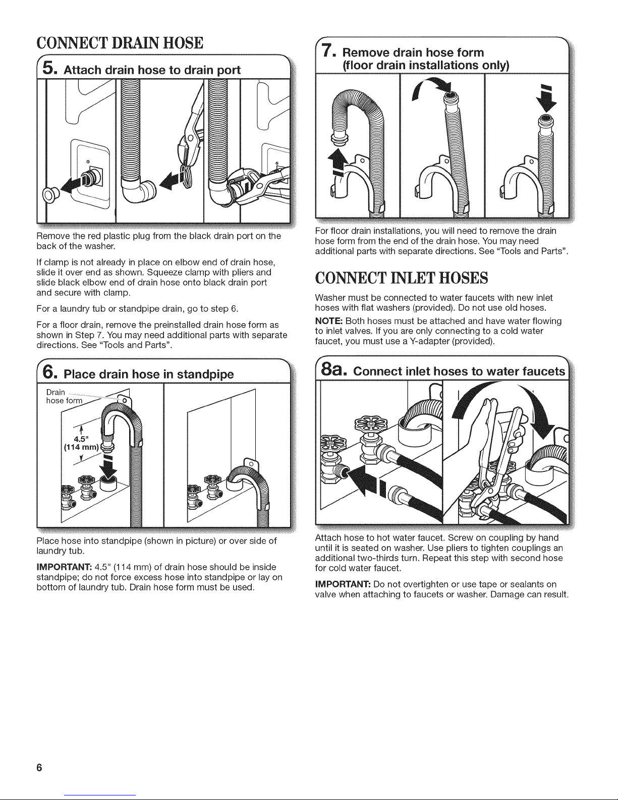
CONNECT DRAIN HOSE
Attach drain hose to drain port
Remove drain hose form
(floor drain installations only}
Remove the red plastic plug from the black drain port on the
back of the washer.
If clamp is not already in place on elbow end of drain hose,
slide it over end as shown. Squeeze clamp with pliers and
slide black elbow end of drain hose onto black drain port
and secure with clamp.
For a laundry tub or standpipe drain, go to step 6.
For a floor drain, remove the preinstalled drain hose form as
shown in Step 7. You may need additional parts with separate
directions. See "Tools and Parts".
F6, Place drain hose in standpipe
Drain
For floor drain installations, you will need to remove the drain
hose form from the end of the drain hose. You may need
additional parts with separate directions. See "Tools and Parts".
CONNECT INLET HOSES
Washer must be connected to water faucets with new inlet
hoses with flat washers (provided). Do not use old hoses.
NOTE: Both hoses must be attached and have water flowing
to inlet valves. If you are only connecting to a cold water
faucet, you must use a Y-adapter (provided).
Connect inlet hoses to water
Place hose into standpipe (shown in picture) or over side of
laundry tub.
IMPORTANT: 4.5" (114 mm) of drain hose should be inside
standpipe; do not force excess hose into standpipe or lay on
bottom of laundry tub. Drain hose form must be used.
6
Attach hose to hot water faucet. Screw on coupling by hand
until it is seated on washer. Use pliers to tighten couplings an
additional two-thirds turn. Repeat this step with second hose
for cold water faucet.
IMPORTANT: Do not overtighten or use tape or sealants on
valve when attaching to faucets or washer. Damage can result.
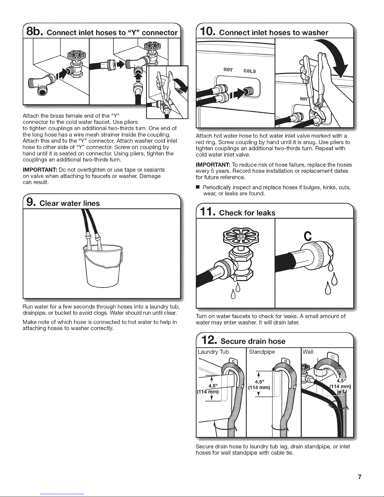
Attach the brass female end of the "Y"
connector to the cold water faucet. Use pliers
to tighten couplings an additional two-thirds turn. One end of
the long hose has a wire mesh strainer inside the coupling.
Attach this end to the "Y" connector. Attach washer cold inlet
hose to other side of "Y" connector. Screw on coupling by
hand until it is seated on connector. Using pliers, tighten the
couplings an additional two-thirds turn.
IMPORTANT: Do not overtighten or use tape or sealants
on valve when attaching to faucets or washer. Damage
can result.
9. Clear water lines
flO. Connect inlet hoses to washer
#0@_' ¢@Li#
Attach hot water hose to hot water inlet valve marked with a
red ring. Screw coupling by hand until it is snug. Use pliers to
tighten couplings an additional two-thirds turn. Repeat with
cold water inlet valve.
IMPORTANT: To reduce risk of hose failure, replace the hoses
every 5 years. Record hose installation or replacement dates
for future reference.
[] Periodically inspect and replace hoses if bulges, kinks, cuts,
wear, or leaks are found.
11. Check for leaks
Run water for a few seconds through hoses into a laundry tub,
drainpipe, or bucket to avoid clogs. Water should run until clear.
Make note of which hose is connected to hot water to help in
attaching hoses to washer correctly.
o
66
Turn on water faucets to check for leaks. A small amount of
water may enter washer. It will drain later.
Standpipe
Secure drain hose to laundry tub leg, drain standpipe, or inlet
hoses for wall standpipe with cable tie.
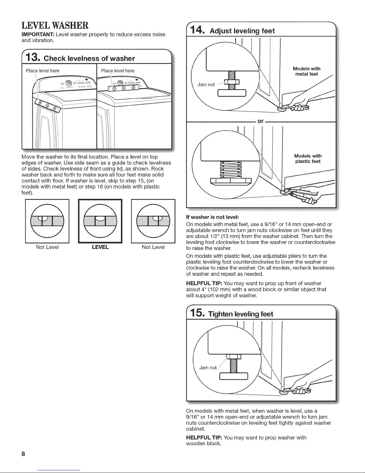
LEVEL WASHER
IMPORTANT: Level washer properly to reduce excess noise
and vibration.
3. Check levelness of washer
4. Adjust leveling feet
N
Place level here Place level here
Move the washer to its final location. Place a level on top
edges of washer. Use side seam as a guide to check levelness
of sides. Check levelness of front using lid, as shown. Rock
washer back and forth to make sure all four feet make solid
contact with floor. If washer is level, skip to step 15, (on
models with metal feet) or step 16 (on models with plastic
feet).
Not Level LEVEL Not Level
Models with
metal feet
Jam nut
Models with
plastic feet
if washer is not level:
On models with metal feet, use a 9/16" or 14 mm open-end or
adjustable wrench to turn jam nuts clockwise on feet until they
are about 1/2" (13 mm) from the washer cabinet. Then turn the
leveling foot clockwise to lower the washer or counterclockwise
to raise the washer.
On models with plastic feet, use adjustable pliers to turn the
plastic leveling foot counterclockwise to lower the washer or
clockwise to raise the washer. On all models, recheck levelness
of washer and repeat as needed.
HELPFUL TIP: You may want to prop up front of washer
about 4" (102 mm) with a wood block or similar object that
will support weight of washer.
8
15. Tighten leveling feet
Jam nut
On models with metal feet, when washer is level, use a
9/16" or 14 mm open-end or adjustable wrench to turn jam
nuts counterclockwise on leveling feet tightly against washer
cabinet.
HELPFUL TIP: You may want to prop washer with
wooden block.
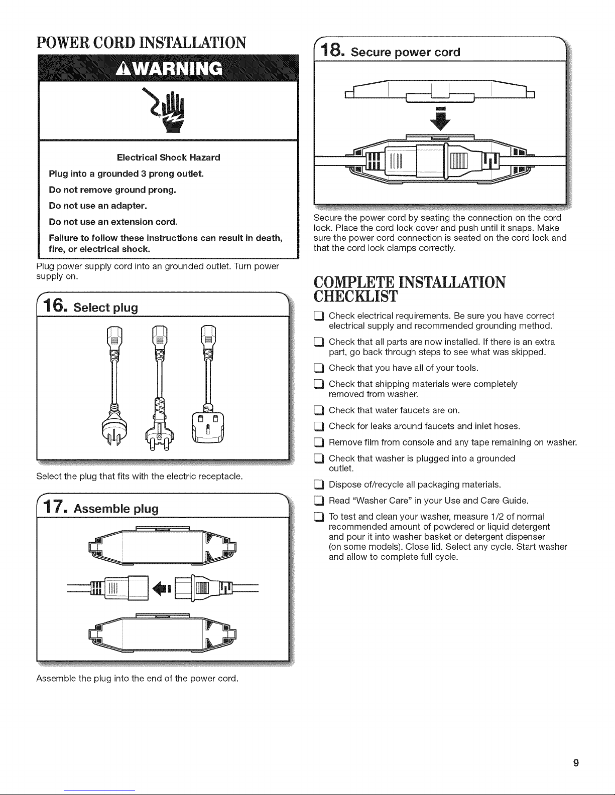
POWER CORD INSTALLATION
"a,
Electrical Shock Hazard
Plug into a grounded 3 prong outlet.
Do not remove ground prong.
Do not use an adapter.
Do not use an extension cord.
Failure to follow these instructions can result in death,
fire, or electrical shock.
Plug power supply cord into an grounded outlet. Turn power
supply on.
Select plug
Select the plug that fits with the electric receptacle.
18, Secure power cord
Secure the power cord by seating the connection on the cord
lock. Place the cord lock cover and push until it snaps. Make
sure the power cord connection is seated on the cord lock and
that the cord lock clamps correctly.
COMPLETE INSTALLATION
CHECKLIST
[_ Check electrical requirements. Be sure you have correct
electrical supply and recommended grounding method.
[_ Check that all parts are now installed. If there is an extra
part, go back through steps to see what was skipped.
[_ Check that you have all of your tools.
[_ Check that shipping materials were completely
removed from washer.
Check that water faucets are on.
C3
Check for leaks around faucets and inlet hoses.
C3
C3
Remove film from console and any tape remaining on washer.
C3
Check that washer is plugged into a grounded
outlet.
C3
Dispose of/recycle all packaging materials.
C3
Read "Washer Care" in your Use and Care Guide.
C3
Totest and clean your washer, measure 1/2 of normal
recommended amount of powdered or liquid detergent
and pour it into washer basket or detergent dispenser
(on some models). Close lid. Select any cycle. Start washer
and allow to complete full cycle.
Assemble the plug into the end of the power cord.
 Loading...