


220–240V 50 Hz WASHER INSTALLATION INSTRUCTIONS
Table of Contents |
|
WASHER SAFETY............................................................... |
2 |
WASHER DISPOSAL.......................................................... |
2 |
INSTALLATION REQUIREMENTS..................................... |
3 |
Tools and Parts..................................................................... |
3 |
Location Requirements........................................................ |
3 |
Drain System......................................................................... |
4. |
Electrical Requirements....................................................... |
5 |
INSTALLATION INSTRUCTIONS....................................... |
5 |
Before you start: remove shipping materials..................... |
5 |
Connect Drain Hose............................................................. |
6 |
Connect Inlet Hoses............................................................. |
7 |
Level Washer......................................................................... |
8 |
Complete Installation Checklist.......................................... |
9 |
INSTALLATION NOTES
Date of purchase:_________________________________________
Date of installation:________________________________________
Installer:__________________________________________________
Model number:____________________________________________
Serial number:____________________________________________
|
Models |
|
6AWTW5700X |
W1004.5638A |
6AWTW5550X |

WASHER SAFETY
WASHER DISPOSAL
2
INSTALLATION REQUIREMENTS
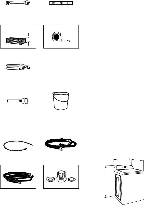
Tools and Parts
Gather required tools and parts before starting installation.
Tools needed:
|
|
|
Adjustable or open-end |
|
Level |
wrench 14 mm (9/16") |
|
|
102 mm min (4") 
Wood block |
Ruler or measuring tape |
|
|
|
|
Pliers that open to 39.5 mm (19⁄16")
Optional tools:
|
|
|
Flashlight |
|
Bucket |
Parts supplied:
NOTE: All parts supplied for installation are in cardboard insert in the top of the washer.
|
|
|
Beaded tie strap |
|
Drain hose with clamp |
|
A |
B |
C |
Water inlet hose (2) |
A Large flat washer (4) |
||
|
B Inlet hose adapter (2) |
||
|
C Small flat washer (2) |
||
Your installation may require additional parts. For information on ordering, contact your dealer.
n8212656RP 3.0 m (10 ft.) Inlet hose, Black EPDM (2 pack)
n8212641RP 1.5 m (5 ft.) Inlet hose, Black EPDM (2 pack)
n8212646RP 1.2 m (4 ft.) Inlet hose, Black EPDM (2 pack)
n8212545RP 1.5 m (5 ft.) Inlet hose, Red and Blue EPDM
(2 pack)
n8212487RP 1.5 m (5 ft.) Nylon braided inlet hose (2 pack)
n8212638RP 1.8 m (6 ft.) Nylon braided inlet hose, space
saving 90° elbow, hypro-blue steel couplings (2 pack)
n 8212637RP 1.8 m (6 ft.) Inlet hose, Black EPDM, space saving 90° elbow, hypro-blue steel couplings (2 pack)
Alternate parts: (Not supplied with washer)
Your installation may require additional parts. For information on ordering, contact your dealer.
If you have: |
You will need: |
||
Overhead sewer |
Standard 76 L (20 gal.) 990 mm (39") |
||
|
tall drain tub or utility sink, sump |
||
|
pump, and connectors (available |
||
|
from local plumbing suppliers) |
||
25 mm (1") standpipe |
51 mm (2") diameter to 25 mm (1") |
||
|
diameter Standpipe Adapter |
||
|
Part Number 3363920 |
||
|
Connector Kit Part Number 285835 |
||
Drain hose too short |
Extension Drain Hose Part |
||
|
Number 285863 |
||
|
Connector Kit Part Number 285835 |
||
Lint clogged drain |
Drain Protector Part Number 367031 |
||
|
Connector Kit Part Number 285835 |
||
Technical Specifications |
|||
|
|
|
|
220–24.0 V |
|
|
Clothes Capacity |
|
|
|
|
~50 Hz. AC |
|
|
6AWTW5550: 8.0 Kg Max. |
|
|
|
|
IP24 |
|
|
6AWTW5700: 8.0 Kg Max. |
|
|
|
|
LOCATION REQUIREMENTS
Select proper location for your washer to improve performance and minimize noise and possible “washer walk.” Install your washer in a basement, laundry room, closet, or recessed area.
699 mm |
686 mm |
(271/2") |
(27") |
1067 mm (42")
3
You will need:
nA water heater set to 60° C (140° F).
nAn earthed electrical outlet located within 1.2 m (4 ft) of power cord on back of washer.
nHot and cold water faucets located within 0.9 m (3 ft) of hot and cold water fill valves on washer, and water pressure of 138–690 kPa (20–100 psi).
nA level floor with maximum slope of 25 mm (1") under entire washer. Installing on carpet is not recommended.
nFloor must support washer’s total weight (with water and load) of 143 kgs (315 lbs).
IMPORTANT: Do not install, store, or operate washer where it will be exposed to weather or in temperatures below 0° C (32° F). Water remaining in washer after use may cause damage in low temperatures. See “Washer Care” in your “Use and Care Guide” for winterizing information.
Proper installation is your responsibility.
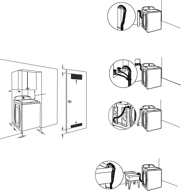
Recessed area or closet installation
76 mm (3")
356 mm |
310 cm2 |
max. |
(48 in.2) |
(14") |
432 mm |
|
|
|
(17") |
155 cm2
126 mm (24 in.2) (5") 
|
25 mm |
|
25 mm |
(1") |
76 mm |
(1") |
|
|
|
(3") |
|
|
|
Dimensions show recommended spacing allowed, except for closet door ventilation openings which are minimum required. This washer has been tested for installation with spacing of
0 mm (0") clearance on the sides. Consider allowing more space for ease of installation and servicing, and spacing for companion appliances and clearances for walls, doors, and floor moldings.
Add spacing of 25 mm (1") on all sides of washer to reduce noise transfer. If a closet door or louvered door is installed, top and bottom air openings in door are required.
DRAIN SYSTEM
Drain system can be installed using a floor drain, wall standpipe, floor standpipe, or laundry tub. Select method you need.
Floor standpipe drain system
Minimum diameter for a standpipe drain: 51 mm (2"). Minimum carry-away capacity: 64 L (17 gal.) per minute. Top of standpipe must be at least 990 mm (39") high; install no higher than 2.44 m (96") from bottom of washer. If you must install higher than
2.44 m (96"), you will need a sump pump system.
Wall standpipe drain system
See requirements for floor standpipe drain system.
Floor drain system
Floor drain system requires a Siphon Break Kit (Part Number 285834), 2 Connector Kits (Part Number 285385), and an Extension Drain Hose (Part Number 285863) that may be purchased separately. To order, contact your dealer. Minimum siphon break: 710 mm (28") from bottom of washer. (Additional hoses may be needed.)
Laundry tub drain system
Minimum capacity: 76 L (20 gal.). Top of laundry tub must be at least 990 mm (39") above floor; install no higher than 2.44 m (96") from bottom of washer.
IMPORTANT: To avoid siphoning, no more than 114 mm (4.5") of drain hose should be inside standpipe or below the top of wash tub. Secure drain hose with beaded tie strap.
4.
 Loading...