


Whirlpool 3LWED5500Y, 3LWGD4800Y, 3LWED4800Y, 3LWED4900Y, 3LMEDC100Y Installation Instructions
...ELECTRIC OR GAS DRYER
INSTALLATION INSTRUCTIONS
INSTRUCTIONS D’INSTALLATION DU SECHE-LINGE
ELECTRIQUE OU A GAZ
SECADORA A GAS O ELÉCTRICA
INSTRUCCIONES DE INSTALACIÓN
Table of Contents
DRYER SAFETY.......................................................................... |
2 |
DRYER DISPOSAL...................................................................... |
5 |
INSTALLATION REQUIREMENTS............................................. |
5 |
Tools and Parts....................................................................... |
5 |
LOCATION REQUIREMENTS.................................................... |
6 |
ELECTRICAL REQUIREMENTS................................................ |
7 |
GAS REQUIREMENTS............................................................... |
8 |
INSTALL LEVELING LEGS......................................................... |
9 |
VENTING REQUIREMENTS....................................................... |
9 |
PLAN VENT SYSTEM............................................................... |
10 |
INSTALL VENT SYSTEM.......................................................... |
12 |
CONNECT VENT....................................................................... |
12 |
LEVEL DRYER.......................................................................... |
13 |
COMPLETE INSTALLATION CHECKLIST............................... |
13 |
REVERSE DOOR SWING (OPTIONAL).................................... |
14 |
TECHNICAL SPECIFICATIONS............................................... |
18 |
TROUBLESHOOTING............................................................... |
18 |
Table des matiéres
SECURITE DU SECHE-LINGE................................................. |
19 |
ELIMINATION DU SECHE-LINGE............................................ |
22 |
EXIGENCES D’INSTALLATION................................................ |
22 |
Outillage et Pièces............................................................... |
22 |
EXIGENCES D’EMPLACEMENT.............................................. |
23 |
SPECIFICATIONS ELECTRIQUES........................................... |
25 |
EXIGENCES CONCERNANT L’ALIMENTATION EN GAZ...... |
26 |
INSTALLATION DES PIEDS DE NIVELLEMENT..................... |
26 |
EXIGENCES CONCERNANT L’EVACUATION......................... |
27 |
PLANIFICATION DU SYSTEME D’EVACUATION................... |
28 |
INSTALLATION DU CONDUIT D’EVACUATION...................... |
30 |
RACCORDEMENT DU CONDUIT D’EVACUATION................ |
30 |
REGLAGE DE L’APLOMB DU SECHE-LINGE........................ |
31 |
ACHEVER L’INSTALLATION LISTE DE VERIFICATION......... |
31 |
INVERSION DU SENS DE L’OUVERTURE DE LA PORTE |
|
(FACULTATIF)............................................................................ |
32 |
CARACTERISTIQUES TECHNIQUES...................................... |
36 |
DEPANNAGE............................................................................. |
36 |
Índice
SEGURIDAD DE LA SECADORA............................................. |
37 |
ELIMINACIÓN DE LA SECADORA.......................................... |
40 |
REQUISITOS DE INSTALACIÓN.............................................. |
40 |
Piezas y herramientas:......................................................... |
40 |
REQUISITOS DE UBICACIÓN................................................. |
41 |
REQUISITOS ELÉCTRICOS..................................................... |
42 |
REQUISITOS DEL SUMINISTRO DE GAS.............................. |
43 |
INSTALACIÓN DE LAS PATAS NIVELADORAS...................... |
44 |
REQUISITOS DE VENTILACIÓN.............................................. |
45 |
PLANIFICACIÓN DEL SISTEMA DE VENTILACIÓN.............. |
46 |
INSTALACIÓN DEL SISTEMA DE VENTILACIÓN.................. |
47 |
CONEXIÓN DEL DUCTO DE ESCAPE.................................... |
48 |
NIVELACIÓN DE LA SECADORA............................................ |
48 |
LISTA DE CONTROL DE LA INSTALACIÓN TERMINADA..... |
49 |
CAMBIO DEL SENTIDO DE ABERTURA DE LA PUERTA |
|
(OPCIONAL).............................................................................. |
49 |
ESPECIFICACIONES TÉCNICAS............................................ |
54 |
SOLUCIÓN DE PROBLEMAS.................................................. |
54 |
|
3LWED5500Y |
3LWGD4800Y |
W10454272C |
3LWED4800Y |
3LWED4900Y |
3LMEDC100Y |
3LMEDC300Y |

DRYER SAFETY
FOR YOUR SAFETY
1.Do not use or store petrol or other ammable materials in this appliance or near this appliance.
2.Do not spray aerosols in the vicinity of this appliance while it is in operation.
3.Do not modify this appliance.
2

3

IMPORTANT SAFETY INSTRUCTIONS
WARNING: To reduce the risk of re, electric shock, or injury to persons when using the dryer, follow basic precautions, including the following:
|
Read all instructions before using the dryer. |
|
|
|
|
Before the dryer is removed from service or discarded, |
|
|
|||||
|
Keep a minimum clearance of 100 mm (4 in.) between the |
|
|
remove the doors to the drying compartment. |
||
|
||||||
|
rear of the dryer and any wall. |
|
|
Do not reach into the dryer if the drum is moving. A door |
||
|
|
|||||
|
|
|||||
|
The operation of this appliance may affect the operation of |
|
|
switch is tted for your safety. |
||
|
||||||
|
other types of appliances which take their air supply for safe |
|
|
Do not install or store the dryer where it will be exposed |
||
|
|
|||||
|
combustion from the same room. There has to be adequate |
|
|
to the weather. |
||
|
ventilation to replace exhausted air and thus avoid the |
|
|
Do not tamper with controls. |
||
|
backow of gases into the room from appliances burning |
|
|
Do not continue to use this appliance if it appears to be |
||
|
other fuels, including open res, when operating the tumble |
|
|
|||
|
|
|
faulty. |
|||
|
dryer. If in doubt, consult the appliance manufacturers. |
|
|
|||
|
|
|
Do not repair or replace any part of the dryer or attempt |
|||
|
Do not obstruct the air supply to the dryer (see Installation |
|
|
|||
|
|
|||||
|
|
|||||
|
|
|
any maintenance unless speci cally recommended in this |
|||
|
Instructions for minimum clearances). |
|
|
|||
|
|
|
Use and Care Guide. Repairs and servicing should only |
|||
|
Do not place items exposed to cooking oils in your dryer. |
|
|
|||
|
|
|
be carried out by competent service personnel. |
|||
|
||||||
|
Oil-affected items can ignite spontaneously, especially when |
|
|
Do not use fabric softeners or products to eliminate static |
||
|
exposed to heat sources such as in a tumble dryer. The |
|
|
|||
|
|
|
unless recommended by the manufacturer of the fabric |
|||
|
items become warm causing an oxidation reaction in the oil. |
|
|
|||
|
|
|
softener or product. Follow their instructions. |
|||
|
Oxidation creates heat. If the heat cannot escape, the items |
|
|
|||
|
|
|
Clean dryer lint screen before or after each load. Do not |
|||
|
can become hot enough to catch re. Piling, stacking or |
|
|
|||
|
|
|||||
|
|
|||||
|
storing oil-affected items can prevent heat from escaping |
|
|
operate dryer without lint screen in place. |
||
|
and so create a re hazard. |
|
|
Keep area around the exhaust and inlet openings and |
||
|
|
|||||
|
|
|||||
|
If it is unavoidable to dry in the dryer items that have been |
|
|
adjacent surrounding areas free from the accumulation of |
||
|
soiled with substances such as cooking oil, acetone, alcohol, |
|
|
lint, dust, and dirt. |
||
|
|
|
The interior of the dryer and exhaust vent should be |
|||
|
petrol, kerosene, spot removers, turpentine, waxes and wax |
|
|
|||
|
|
|||||
|
|
|||||
|
removers, or that have been contaminated by hair care |
|
|
cleaned periodically by quali ed service personnel. |
||
|
products, should be washed in hot water with an extra |
|
|
See Installation Instructions for earthing instructions. |
||
|
|
|||||
|
amount of detergent before being dried in the dryer. These |
|
||||
|
|
|
Do not dry unwashed items in this dryer. |
|||
|
items may give off vapours that could ignite or explode. Such |
|
|
|||
|
|
|||||
|
|
|
The nal part of a tumble dryer cycle occurs without heat |
|||
|
washing will reduce, but not eliminate, the hazard. |
|
|
|||
|
|
|
(cool down cycle) to ensure that the items are left at a |
|||
|
This appliance is not intended for use by persons (including |
|
|
|||
|
|
|
temperature that ensures the items will not be damaged. |
|||
|
||||||
|
||||||
|
children) with reduced physical, sensory or mental |
|
|
Items such as foam rubber (latex foam), shower caps, |
||
|
capabilities, or lack of experience and knowledge, unless |
|
|
|||
|
|
|||||
|
|
|
waterproof textiles, rubber backed articles and clothes or |
|||
|
they have been given supervision or instructions concerning |
|
|
|||
|
|
|
pillows tted with foam rubber pads must only be dried |
|||
|
use of the appliance by persons responsible for their safety. |
|
|
|||
|
|
|
on a clothesline. |
|||
|
Children should be supervised to ensure that they do not |
|
|
|||
|
|
|
If the supply cord is damaged, it must be replaced by the |
|||
|
|
|
||||
|
play with the appliance. |
|
|
|||
|
|
|
||||
|
|
|
manufacturer or its service agent or a similarly quali ed |
|||
|
The dryer should not be used if industrial chemicals have |
|
|
|||
|
|
|
person in order to avoid a hazard. |
|||
|
||||||
|
||||||
|
been used for cleaning. |
WARNING: Never stop a tumble dryer cycle before the |
||||
|
|
|
|
|||
|
|
|
|
end of the drying cycle unless all items are quickly removed |
||
|
|
|
|
and spread out so that the heat is dissipated. |
||
SAVE THESE INSTRUCTIONS
4
DRYER DISPOSAL
INSTALLATION REQUIREMENTS
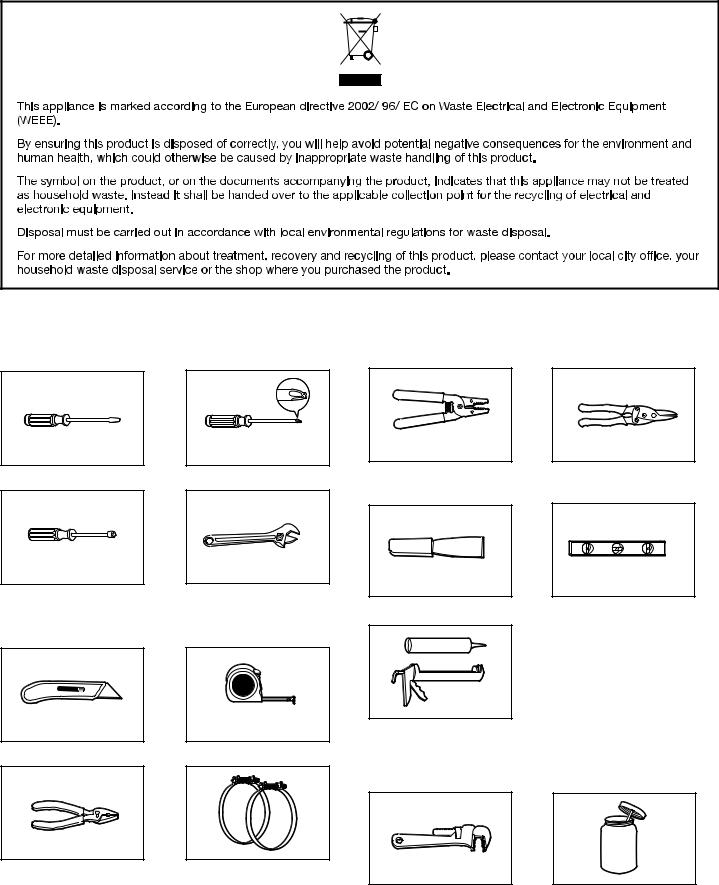
Tools and Parts:
Gather required tools and parts before starting installation.
Flat-blade screwdriver
6,2 mm (1/4") nut driver
Utility knife
Pliers
#2 Phillips screwdriver
Adjustable wrench that opens to 25 mm (1") or hex-head socket wrench (for adjusting dryer feet)
Tape measure
Vent clamps
Wire stripper
(direct wire installations)
Putty knife
Tin snips
(new vent installations)
Level
Caulking gun and compound (for installing new exhaust vent)
Tools needed for Gas installations:
204 mm (8") or 254 mm (10") |
Pipe joint compound |
pipe wrench |
resistant to LP gas |
5
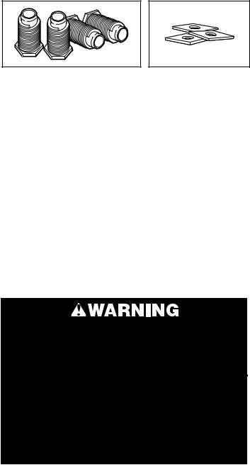
Parts supplied:
Leveling legs (4) |
Square washers (3) |
|
* Included with models |
|
without preinstalled |
|
power cords |
Parts package is located in dryer drum. Check that all parts are included.
Parts needed: (not supplied with dryer)
■■ Electric cord and plug; model specific - check to see if your model comes with a pre-installed power cord.
■■ Vent clamps
■■ Vent elbows and ductwork
For gas installation:
Check local codes and gas supplier, and read electrical, gas, and venting requirements before purchasing parts.
Gas supply line must have: ■■ Shutoff valve
Rigid gas supply line must be:
■■ Minimum 12.5 mm (1/2") ID pipe
Flexible gas supply line must be:
■■ Minimum 10 mm (3/8") ID approved flexible hose
L.P. Gas Conversion:
Gas conversion kit, part number 279918, available for purchase from your dealer. Full instructions are supplied with the kit. Conversion must be made by a competent technician.
Additional parts may be required, depending on your installation. Check local codes. Check existing venting and electrical and gas supply. Read “Electrical Requirements,” "Gas Requirements," and “Venting Requirements” before purchasing parts.
LOCATION REQUIREMENTS
Select proper location for your dryer to improve performance and minimize noise. Check code requirements. Some codes limit, or do not permit, installation of the dryer in garages, closets, mobile homes, or sleeping quarters. Contact your local building inspector.
You will need:
■■ A location that allows for proper exhaust installation. The dryer must be exhausted to the outdoors. See “Venting Requirements.”
■■ An earthed electrical outlet located within 610 mm (2 ft) of either side of the dryer. See “Electrical Requirements.”
■■ A floor that will support the dryer and a total weight (dryer and load) of 90,7 kg (200 lbs). The combined weight of a companion appliance should also be considered.
■■ A level floor with maximum slope of 25 mm (1") under entire dryer. If slope is greater than 25 mm (1"), install Extended Dryer Feet Kit, Part No. 279810. Clothes may not tumble properly and models with automatic sensor cycles may not operate correctly if dryer is not level.
■■ It is important to make sure the room has an adequate air supply for drying operation. The operation of this appliance may affect the operation of other appliances which take their air supply for safe combustion from the same room.
■■ Adequate ventilation must be provided to avoid a backflow of gases into the room from appliances burning other fuels, including open fires. If in doubt consult the appliance manufacturers.
IMPORTANT: The dryer must not be installed or stored in an area where it will be exposed to water and/or weather. Do not operate your dryer at temperatures below 7°C (45°F). At lower temperatures, the dryer might not shut off at the end of an automatic cycle. Drying times can be extended.
Proper installation is your responsibility.
Installation clearances:
For each arrangement, consider allowing more space for ease of installation and servicing; spacing for companion appliances and clearances for walls, doors, and floor moldings. Space must be large enough to allow door to fully open. Add spacing on all sides of dryer to reduce noise transfer. If a closet door or louvered door is installed, top and bottom air openings in door are required.
6

Dryer Dimensions
Front View:
 686 mm
(27") 98 mm (3 7/ 8")
|
|
|
|
|
|
|
|
|
|
|
|
|
|
|
|
|
|
1095 mm |
|
489 mm |
|||
(43.15/ 8") |
|
(19.15/ 8") |
|||
|
|
|
|
|
|
|
|
|
|
|
|
 578 mm
  (22.35/ 4")
Side View:
 743 mm
  (29.15/ 4")
 356 mm
  (14")
(14")
108 mm (4.15/ 4 ")
260 mm
(10.15/ 4")
Back View:
279 mm
(11")
972 mm
(38.15/ 4")
100 mm (4")
359 mm
(14.15/ 8 ")
Side View of Side Swing Door:
 743 mm
  (29.15/ 4")
 578 mm
  (22.35/ 4")
108 mm (4.15/ 4 ")
260 mm
(10.15/ 4")
Recessed Area and Closet Installation
This dryer may be installed in a recessed area or closet.
If a closet door or louvered door is installed, the minimum unobstructed air openings in the top and bottom of the door
are required. For recessed area and closet installations, minimum clearances can be found on the serial tag on the dryer.
356 mm (14") max.
|
76 mm |
|
(3") 310 mm |
457 mm |
(48" ) |
|
|
(18") |
|
155 mm
76 mm (24" ) (3") 
102 mm
(4")  25 mm (1")
25 mm (1")
■■ Dimensions shown are minimum spacings required. Consider allowing more space for ease of installation, servicing, and compliance with local codes and ordinances.
■■ Additional spacing for companion appliances and clearances for walls, doors, and floor moldings should also be considered. Add spacing of 25 mm (1") on all sides of dryer to reduce noise transfer.
■■ This dryer must not be installed behind a lockable door, a sliding door or a door with a hinge on the opposite side to that of the dryer.
■■ The dryer must be exhausted outdoors.
■■ No other fuel-burning appliance may be installed in the same closet as the dryer.
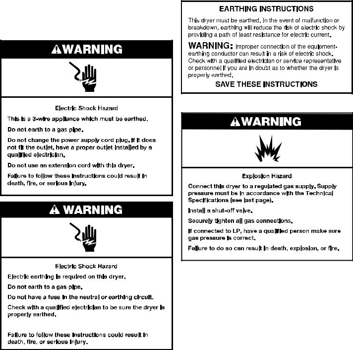
ELECTRICAL REQUIREMENTS
IMPORTANT: Observe all governing codes and ordinances.
If the model comes with a pre-installed power cord, do not modify or replace.
Some models are supplied without an electric cord and plug. It must be connected by a qualified electrician to a single-phase electricity supply at the voltage shown on the dataplate, using a suitable fixed wiring installation in accordance with local and national wiring regulations.
nA 3-wire circular cord of minimum conductor size of 4 mm2 cross-section area should be used.
nA 30A supply fuse should be used, and a switch with a minimum contact separation of 3 mm in both poles must be incorporated into the fixed wiring for dryer disconnection. The dryer should be positioned so that the disconnection switch is easily accessible to the user.
nA cord clamp bushing is provided on the dryer, and should be tightened on completion of wiring. The electrical mains terminals are located behind the small rear access panel (terminal block cover), and connections should be made in accordance with the terminal markings. Remember to replace the terminal access panel (terminal block cover).
nIf using an unterminated power cord, the square washers that are provided
must be used.
7
NOTE: In accordance with the European EMC Directive (89/336/EEC) the maximum electricity supply system impedance to which the electric dryer should be connected is declared to be 0.29 Ohm + J0.18 Ohm.
This dryer has a Maximum power absorption/usage of 4700 watts.
GAS REQUIREMENTS


 /
/


If code permits and an additional earth bond wire is used, it is recommended that certified electrician determine that the earth bond path is adequate.
Electrical Safety Standards: The manufacturer has chosen compliance with IEC/EN.60335 standards as the most appropriate for this product.
Do not use an adapter.
Recommended Earthing Method
■■ It is your responsibility to contact a qualified electrical installer to ensure that the electrical installation is adequate and in conformance with all local codes and ordinances.
OBSERVE ALL GOVERNING CODES AND ORDINANCES.
Gas supply:
Check that dryer is equipped with the correct burner for the particular type of gas supply. Burner information will be found on the model/serial rating plate in the door well of the dryer. If this information does not agree with the type of gas available, see your dealer.
Natural Gas:
This dryer is factory adjusted for use with NATURAL GAS (G20), and no further adjustment should be required at installation.
L.P. Gas:
This dryer is also certified for use with L.P. (propane or butane) gases with appropriate conversion. No attempt shall be made to convert the appliance from the gas specified on the model/serial rating plate for use with a different gas without consulting the serving gas supplier.
Conversion must be done by a qualified service technician.
Gas conversion kits are available for purchase from your dealer. Full instructions are supplied with the kit.
Supply Line Requirements
Provide a rigid gas supply line to the dryer location. It should be minimum 12.5 mm (1/2") ID. When acceptable to the gas supplier and local codes, 10 mm (3/8") ID rigid supply line may be used for lengths under 6.1 m (20'). Pipe-joint compounds resistant to the action of L.P. gas must be used.
8
Gas connection to the dryer itself should be made by means of a flexible gas hose suitable for the appliance and gas category in accordance with national installation regulations. If in doubt, contact the gas supplier. It should be minimum 10 mm (3/8") ID.
A means of restraint should be used between the appliance and the wall to prevent straining of the rigid gas supply when the appliance is moved. An appropriate length of chain and a wall hook is recommended.
The dryer gas inlet connection is a 10 mm (3/8") NPT thread. An adapter is supplied for conversion to standard ISO.228-1 thread 10 mm (3/8" BSP).
Check for leaks by using an approved noncorrosive leak detection solution. Bubbles will show a leak. Correct any leak found. A pressure measurement tapping is provided on the gas valve within the dryer, accessible after removal of the lower front panel.
Gas supply pressure testing
The dryer must be disconnected from the gas supply piping system during any pressure testing of that system.
INSTALL LEVELING LEGS
1. Prepare dryer for leveling legs
To avoid damaging floor, use a large flat piece of cardboard from dryer carton; place under entire back edge of dryer. Firmly grasp dryer body (not console panel) and gently lay dryer down on cardboard.
2. Screw in leveling legs
diamond marking
Examine leveling legs, find diamond marking. Screw legs into leg holes by hand, use a wrench to finish turning legs until diamond marking is no longer visible.
Now stand the dryer on its feet. Slide the dryer until it is close to its final location. Leave enough room for electrical connection and to connect the exhaust vent.
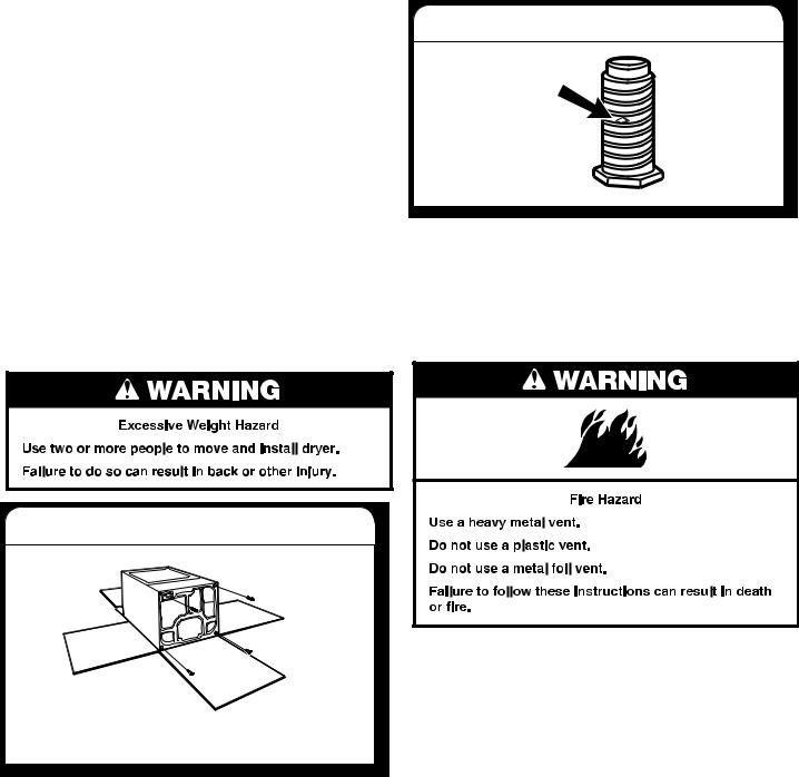
VENTING REQUIREMENTS
WARNING: To reduce the risk of fire, this dryer MUST BE EXHAUSTED OUTDOORS.
WARNING: Gas dryers should only be installed in a room if the room meets the appropriate ventilation requirements specified in the national installation regulations. Make sure the room containing the dryer has an adequate air supply for gas combustion and drying operation. A window or equivalent
means of ventilation must be opened in the room when the dryer is in use (an equivalent form of opening includes an adjustable louver, hinged panel, or other means of ventilation that opens directly to outside air.
WARNING: The design of the flue system should ensure that any condensate formed when operating the appliance is either retained or subsequently evaporated or discharged. Following these installation instructions should adequately meet this requirement.
9
IMPORTANT: Observe all governing codes and ordinances. Dryer exhaust must not be connected into any gas vent, chimney, wall, ceiling, attic, crawlspace, or a concealed space of a building. Only rigid or flexible metal vent shall be used for exhausting.
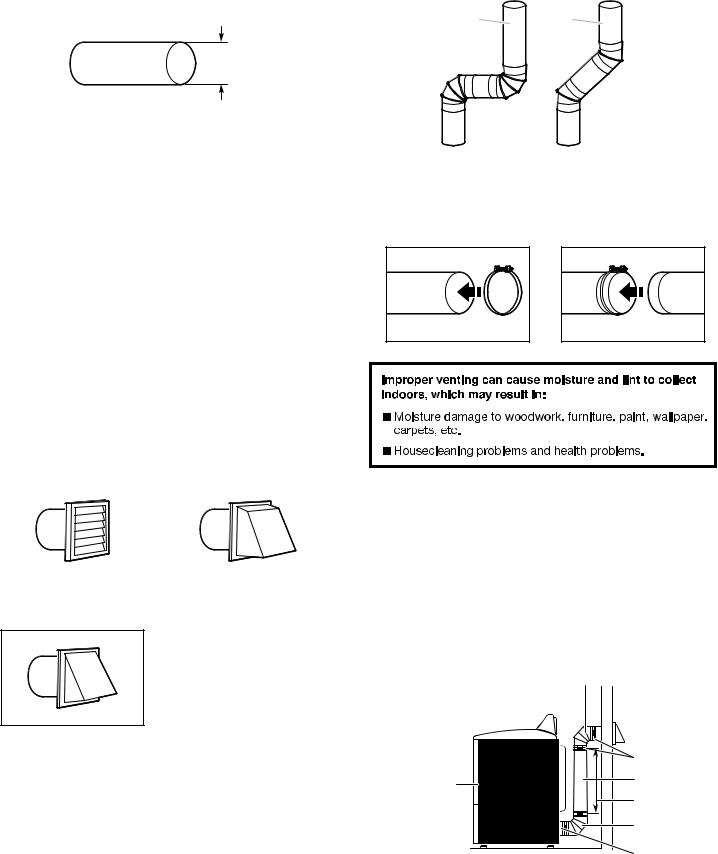
102 mm (4")
■■ Only a 102 mm (4") heavy metal exhaust vent and clamps may be used. Do not install metal vent that is smaller than 102 mm (4") in diameter.
■■ Do not use plastic, non-metal, or metal foil vent
Rigid metal vent
■■ Recommended for best drying performance and to avoid crushing and kinking.
Flexible metal vent: (Acceptable only if accessible to clean) ■■ Must be fully extended and supported in final dryer location.
■■ Remove excess flexible metal vent to avoid sagging and kinking that may result in reduced airflow and poor performance.
■■ Do not install in enclosed walls, ceilings, or floors. ■■ The total length should not exceed 2.4 m (7 3/4 ft.).
NOTE: If using an existing vent system, clean lint from entire length of the system and make sure exhaust hood is not plugged with lint. Replace plastic or metal foil vents with rigid metal or flexible metal vents. Review "Vent System Chart" and if necessary, modify existing vent system to achieve best drying performance.
Exhaust hoods:
Recommended Styles:
|
|
|
Louvered Hood |
|
Box Hood |
Acceptable Style:
Angled Hood
■■ An exhaust hood should cap the vent to keep rodents and insects from entering the home.
■■ Exhaust hood must be at least 305 mm (12") from the ground or any object that may be in the path of the exhaust (such as flowers, rocks, bushes, or snow line, etc.).
■■ Do not use an exhaust hood with a magnetic latch.
Elbows:
■■ 45° elbows provide better airflow than 90° elbows.
Good Better
Clamps:
■■ Use clamps to seal all joints.
■■ Exhaust vent must not be connected or secured with screws or other fastening devices that extend into interior of duct and catch lint. Do not use duct tape.
Vent products can be purchased from your dealer. For more information, see “Assistance or Service” section in your “Use and Care Guide.”
PLAN VENT SYSTEM
The design of the flue system should ensure that any condensate formed when operating the appliance from cold, is either retained and subsequently evaporated or discharged. Following these installation instructions should adequately meet this requirement.
Recommended exhaust installations
Typical installations vent the dryer from the rear of the dryer. Other installations are possible.
A
A.Dryer
B.Elbow
C.Wall
D.Exhaust hood
B
 C
C
 D
D
E |
F |
G |
B
H
E.Clamps
F.Rigid metal or flexible metal vent
G.Vent length necessary to connect elbows
H.Exhaust outlet
10
Optional exhaust installations (on some models)
This dryer can be converted to exhaust out the right side, left side, or through the bottom. If you prefer, you may contact your local dealer to have the dryer converted.
A B C
A.Standard rear offset exhaust installation
B.Left or right side exhaust installation
C.Bottom exhaust installation
Alternate installations for close clearances
Venting systems come in many varieties. Select the type best for your installation. Two close-clearance installations are shown. Refer to the manufacturer’s instructions.
Over-The-Top installation (also available with one offset elbow)
Periscope installation
Determine vent path:
■■ Select route that will provide straightest and most direct path outdoors.
■■ Plan installation to use fewest number of elbows and turns. See “Venting Requirements.”
■■ When using elbows or making turns, allow as much room as possible.
■■ Bend vent gradually to avoid kinking. ■■ Use as few 90° turns as possible.
Determine vent length and elbows needed for best drying performance:
■■ Use following Vent System Chart to determine type of vent material and hood combinations acceptable to use.
NOTE: Do not use vent runs longer than those specified in Vent System Chart. Exhaust systems longer than those specified will:
■■ Shorten life of dryer.
■■ Reduce performance, resulting in longer drying times and increased energy usage.
11
The Vent System Chart provides venting requirements that will help achieve best drying performance.
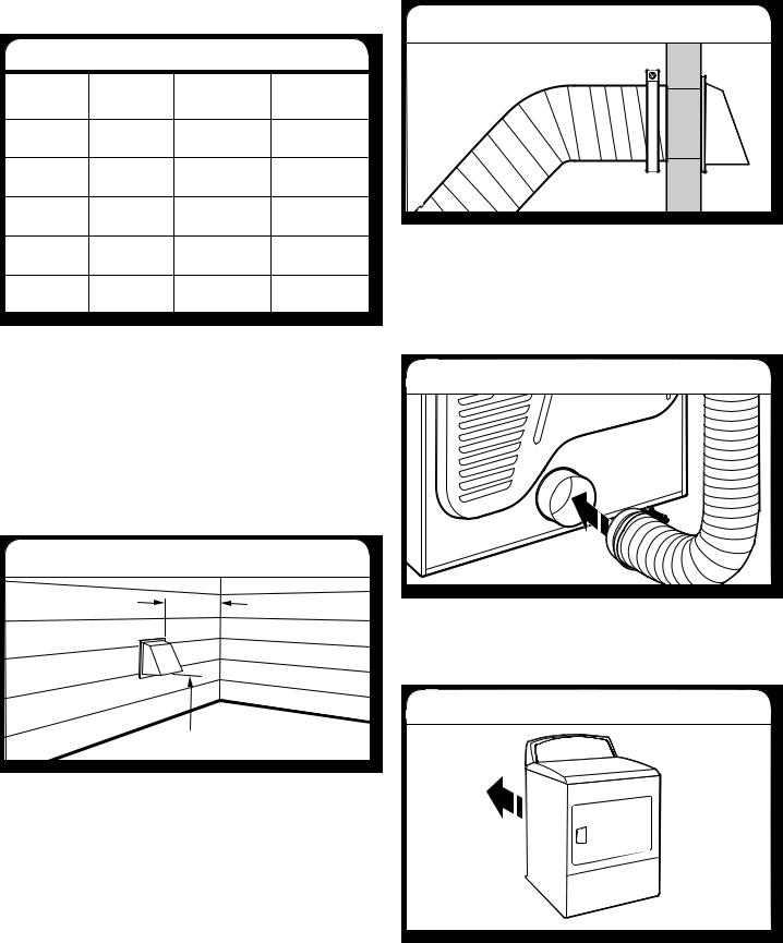
Vent System Chart
Number of |
Type |
Box/louvered |
Angled |
90° turns |
of vent |
hoods |
hoods |
or elbows |
|
|
|
0 |
Rigid metal |
15,8 m (52 ft.) |
13,4 m (44 ft.) |
1 |
Rigid metal |
13,4 m (44 ft.) |
11,0 m (36 ft.) |
2 |
Rigid metal |
11,0 m (36 ft.) |
18,5 m (28 ft.) |
3 |
Rigid metal |
8,2 m (27 ft.) |
6,4 m (21 ft.) |
4 |
Rigid metal |
6,1 m (20 ft.) |
4,3 m (14 ft. |
NOTE: Side and bottom exhaust installations have a 90° turn inside the dryer. To determine maximum exhaust length, add one 90° turn to the chart.
The maximum length using a 51 mm x 152 mm (2"x 6") rectangular vent with 2 elbows and a 64 mm (2-1/2") exhaust hood is 2,4 m (8ft).
For exhaust systems not covered by the Vent System Chart (such as multiple unit hookups, plenums, and power-assist fans), see Service Manual, Part 603197. (To purchase the Service Manual, contact your local authorized service dealer.
INSTALL VENT SYSTEM
1. Install exhaust hood
305 mm (12" mín.)
305 mm  (12" mín.)
Install exhaust hood and use caulking compound to seal exterior wall opening around exhaust hood.
2. Connect vent to exhaust hood
Vent must fit over the exhaust hood. Secure vent to exhaust hood with 102 mm (4") clamp. Run vent to dryer location using straightest path possible. Avoid 90° turns. Use clamps to seal all joints. Do not use duct tape, screws, or other fastening devices that extend into interior of vent to secure vent, because they can catch lint.
CONNECT VENT
1. Connect vent to exhaust outlet
Using a 102 mm (4") clamp, connect vent to exhaust outlet in dryer. If connecting to existing vent, make sure vent is clean. Dryer vent must fit over dryer exhaust outlet and inside exhaust hood. Check that vent is secured to exhaust hood with a 102 mm (4") clamp.
2. Move dryer to final location
Move dryer to final location. Avoid crushing or kinking vent. After dryer is in place, remove corner posts and cardboard from under the dryer.
12
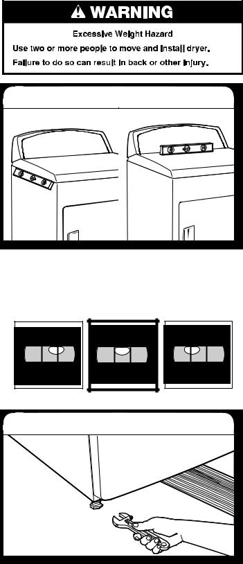
LEVEL DRYER
1. Level Dryer |
Check levelness of dryer from side to side. Repeat from front to back.
NOTE: The dryer must be level to reduce noise and assure proper performance.
If legs are not long enough to level dryer, order Extended Dryer Feet kit, Part No. 279810 (sold two legs per kit), from your dealer.
Not Level |
LEVEL |
Not Level |
1. Tighten and adjust leveling legs
If dryer is not level, prop up using a wood block, use wrench to adjust legs up or down, and check again for levelness. Once legs are level, make sure all four legs are snug against the ground.
COMPLETE INSTALLATION
CHECKLIST
qCheck that all parts are now installed. If there is an extra part, go back through steps to see what was skipped.
qCheck that dryer legs are properly installed.
qCheck that you have all of your tools.
qDispose of/recycle all packaging materials.
qCheck dryer’s final location. Be sure vent is not crushed or kinked.
qSecure all exhaust vent joints with 102 mm (4")clamps.
qFor power supply cord installation, plug into an earthed outlet. For direct wire installation, turn on power.
qCheck that dryer is level. See “Level Dryer”.
qRemove film on console and any tape remaining on dryer.
qWipe dryer drum interior thoroughly with a damp cloth to remove any dust.
qRead “Dryer Use” in your Use and Care Guide.
qSet the dryer on a full heat cycle (not an air cycle) for
20 minutes and start the dryer. (If you have a gas dryer, it is equipped with an electronic ignition system for the burner which is fully automatic; no action is needed by the user (there is no pilot light).
If the dryer will not start, check the following:
■■ Controls are set in a running or “On” position. ■■ Start button has been pushed firmly.
■■ Dryer is plugged into an outlet and/or electrical supply is on.
■■ Household fuse is intact and tight, or circuit breaker has not tripped.
■■ Dryer door is closed.
qWhen the dryer has been running for 5 minutes, open the dryer door and feel for heat. If you feel heat, cancel cycle and close the door.
If you do not feel heat, turn off dryer, and check the following:
■■ There may be 2 household fuses or circuit breakers for the dryer. Check that both fuses are intact and tight, or that both circuit breakers have not tripped. If there is still no heat, contact a qualified technician.
NOTE: You may notice an odor when the dryer is first heated. This odor is common when the heating element is first used. The odor will go away.
13
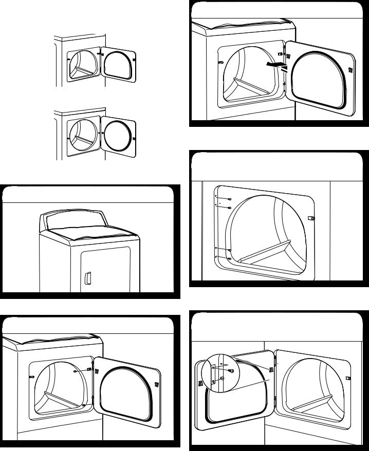
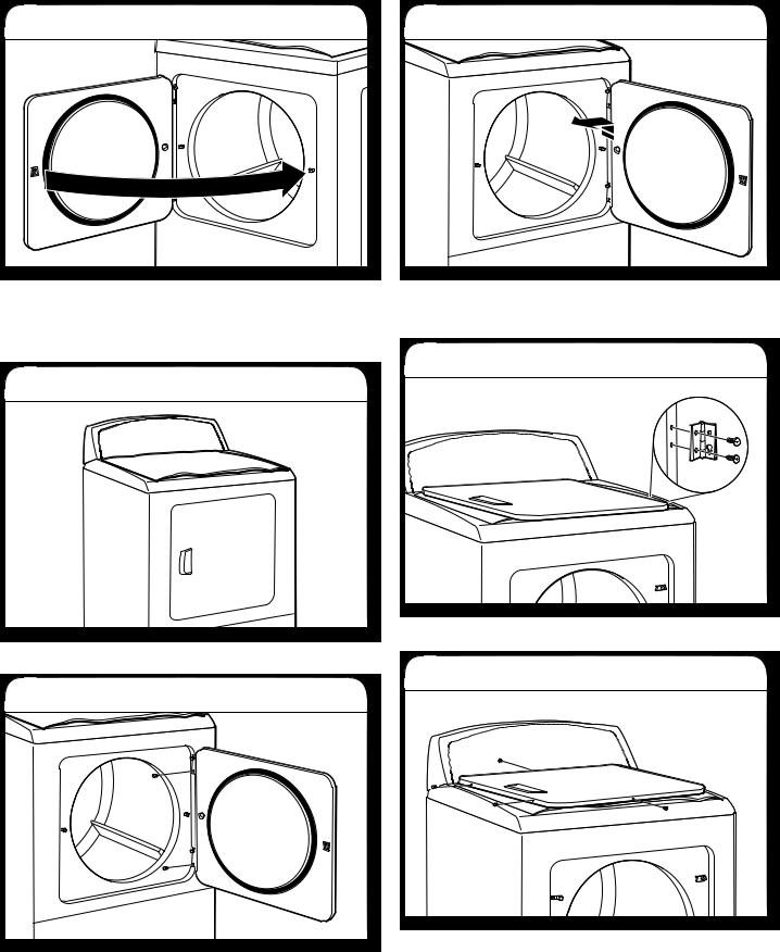
REVERSE DOOR SWING (OPTIONAL)
If your door is the 29" Large Side-Swing Door, follow steps 1-6.
If your door is the 29" Super Wide Side-Swing Door, follow steps 1-13.
NOTE: Magnetized screw driver is helpful.
Large Side-Swing Door
1. Place towel on dryer
Place towel on top of dryer to avoid damaging the surface.
2. Remove bottom screws
Open dryer door. Remove bottom screws from dryer cabinet side of hinges. Loosen (do not remove) top screws from dryer cabinet side of hinges.
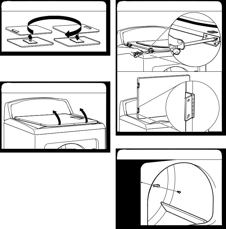
3. Lift door off top screws
Lift door until top screws in cabinet are in large part of hinge slot. Pull door forward off screws. Set door on top of dryer. Remove top screws from dryer cabinet.
4. Remove and transfer hinge hole plugs
Use a small, flat-blade screwdriver to gently remove 4 hinge hole plugs on left side of dryer cabinet. Insert plugs into hinge holes on opposite side of dryer cabinet.
5. Insert screws in hinge holes on dryer cabinet
NOTE: Two people maybe needed to reinstall door.
Insert screws into bottom holes on left side of dryer cabinet. Tighten screws halfway. Position door so large end of door hinge slot is over screws. Slide door up so screws are in bottom of slots. Tighten screws. Insert and tighten top screws in hinges.
14
6. Check door strike alignment |
3. Lift door off top screws |
Close door and check that door strike aligns with door catch. If needed, slide door catch left or right within slot to adjust alignment.
Super Wide Side-Swing Door
1. Place towel on dryer
Place towel on top of dryer to avoid damaging the surface.
2. Remove bottom screws
Open dryer door. Remove bottom screws from dryer cabinet side of hinges. Loosen (do not remove) top screws from dryer cabinet side of hinges.
Lift door until top screws in dryer cabinet are in large part of hinge slot. Pull door forward off screws. Set door (handle side up) on top of dryer. Remove top screws from dryer cabinet.
4. Remove screws from hinges
Remove screws attaching hinges to door.
5. Remove screws from door
Remove screws at top, bottom, and side of door
(4 screws). Keep door screws separate from hinge screws as they are different sizes. Holding door over towel on dryer, grasp sides of outer door and lift to separate it from inner door.
NOTE: Do not pry apart with putty knife or screwdriver. Do not pull on door seal or plastic door catches.
15
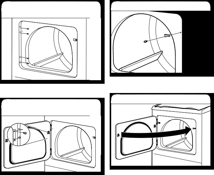
6. Rotate outer door |
8. Attach door hinges |
Take outer door and rotate in 180º and set it back down on inner door. Be certain to keep cardboard spacer centered between doors. Reattach outer door panel to inner door panel so handle is on the side where hinges were just removed. Insert 4 door screws.
7. Flip door over
Flip door over so handle side is down.
Reattach door hinges to dryer door so that the larger hole is at the bottom of the hinge.
9. Remove door strike
Remove door strike from dryer cabinet and set aside.
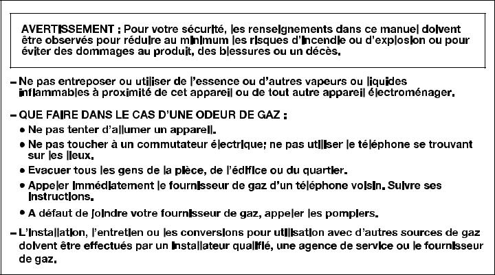
16
10. Remove and transfer |
12. Remove door strike plug |
hinge hole plugs |
|
Use a small, flat-blade screwdriver to gently remove 4 hinge hole plugs on left side of dryer cabinet. Transfer plugs into hinge holes on opposite side of dryer cabinet.
11. Insert screws in hinge holes on dryer cabinet
NOTE: Two people maybe needed to reinstall door.
Insert screws into the bottom holes on left side of dryer cabinet. Tighten screws halfway. Position door so large end of door hinge slot is over screws. Slide door up so screws are in bottom of slots. Tighten screws. Insert and tighten top screws in hinges.
Remove door strike plug. Insert the door strike removed in Step 9 into hole and secure with screw. Insert door strike plug into original door strike hole and secure with screw.
13. Check door strike alignment
Close door and check that door strike aligns with door catch. If it is needed, slide door catch left or right within slot to adjust alignment.
17

TECHNICAL SPECIFICATIONS |
|
|
|
||
|
|
|
|
|
|
|
220-240V~50Hz 1ph 3A max. IPX4 |
|
|
|
|
|
|
|
|
||
|
Maximum Power Absortion/Usage: 4700 Watts |
Moisture Resistance (Water Ingress, Rain Test): 5500-5600 |
|||
|
|
|
|
||
|
Factory set for NATURAL GAS: Injector: 2,2 mm |
Heat input gross: 5,9 kW |
|||
|
|
|
|
|
|
|
European Country: |
CZ, CY, ES, GB, GR, HR, IE, IT, |
|
CY, CZ, DK, EE, FI, GR, HU, IT, |
|
|
|
|
PT, SI, SK, TR |
|
NO, RO, SE, SK, TR |
|
European Gas Category: |
|
II2H3+ |
|
II2H3B/P |
|
Gas Flow Rate: |
|
0.562703 M3/HR |
|
0.562703 M3/HR |
|
Supply Pressure (G20): |
|
20 mbar |
|
20 mbar |
|
Factory Adjusted Pressure: |
|
7.4 mbar |
|
7.4 mbar |
|
|
|
|
||
|
With LP Gas Conversion Kit: Injector size: 1,25 mm Heat input gross: 6,4 kW |
|
|||
|
|
|
|
|
|
|
European Country: |
CZ, CY, ES, GB, GR, HR, IE, IT, |
|
CY, CZ, DK, EE, FI, GR, HU, IT, |
|
|
|
|
PT, SI, SK, TR |
|
NO, RO, SE, SK, TR |
|
European Gas Category: |
|
II2H3+ |
|
II2H3B/P |
|
Butane Supply Pressure (G30): |
|
28-30 mbar |
|
30 mbar |
|
Adjusted Pressure: |
|
N/A |
|
N/A |
|
Propane Supply Pressure (G31): |
|
37 mbar |
|
30 mbar |
|
Adjusted Pressure: |
|
N/A |
|
N/A |
|
With France/Belgium NATURAL GAS conversion kit: Injector size: 1,65 mm |
|
Heat input gross: 5,9 kW |
||
|
|
|
|
|
|
|
European Country: |
|
|
FR, BE |
|
|
European Gas Category: |
|
|
I2E+ |
|
|
Supply Pressure (G20): |
|
|
20 mbar |
|
|
|
|
|
|
|
|
Supply Pressure (G25): |
|
|
25 mbar |
|
|
|
|
|
|
|
|
Adjusted Pressure: |
|
|
N/A |
|
|
|
|
|
||
|
Note: Conversion kit: From Natural Gas to LP Gas : Whirlpool Part No. W10233219. |
||||
|
Conversion kit: From Natural Gas to Natural Gas - France/Belgium: Whirlpool Part No. W10184947. |
||||
|
Manufacturer: Whirlpool Corporation, Benton Harbor, Michigan 49022, USA. |
||||
|
|
|
|
|
|
These units are sold in multiple regions with different requirements for measuring capacity. Below are a few of the valid forms of measure posted on this product:
Dry Linen Capacity: A weight measure that reflects a maximum load size that can be loaded into the dryer.
IEC Capacity: The capacity measure that represents the maximum capacity of dry linens and textiles which the manufacturer declares can be treated in a specific cycle.
Dry Linen Capacity |
|
IEC Capacity |
|
|
|
10,5 kg (23 lb) |
|
7,5 kg (16,5 lb) |
|
|
|
TROUBLESHOOTING
See the “Use and Care Guide” to possibly avoid the cost of a service call.
18

SECURITE DU SECHE-LINGE
19
20
IMPORTANTES INSTRUCTIONS DE SECURITE
AVERTISSEMENT : AŠn de réduire le risque d’incendie, de choc électrique ou de blessures corporelles lors de l’utilisation du sèche-linge, il convient d’observer certaines précautions fondamentales, notamment :
 Lire toutes les instructions avant d’utiliser le sèche-linge.
 Laisser un dégagement minimal de 100 mm (4") entre l’arrière du sèche-linge et les éventuelles parois environnantes.
 Le fonctionnement de cet appareil peut affecter celui d’autres appareils dont la source d’approvisionnement en air se fait dans la même pièce pour une combustion sans danger. Lorsqu’on utilise le sèche-linge, une aération adéquate est nécessaire pour renouveler l’air rejeté et ainsi éviter le retour dans la pièce de gaz en provenance d’appareils ménagers utilisant d’autres carburants comme combustible, y compris les feux ouverts. En cas de doute, consulter le fabricant de l’appareil.
 Ne pas obstruer l’alimentation en air du sèche-linge (voir les instructions d’installation pour les dégagements minimaux).
 Ne pas placer d’articles tâchés d’huile de cuisson dans le sèche-linge. Des articles ayant été au contact d’huile peuvent s’en†ammer spontanément, surtout s’ils sont exposés à des sources de chaleur, telles un sèche-linge. Les articles peuvent chauffer, entraînant une réaction d’oxydation de l’huile. Le phénomène d’oxydation crée de la chaleur. Si la chaleur ne peut pas s’échapper, les articles peuvent devenir sufŠsamment chauds pour prendre feu. Le fait d’empiler, d’entasser ou d’entreposer des articles ayant été au contact d’huile peut empêcher la chaleur de s’échapper et créer un risque d’incendie.
 Si l’on doit faire sécher dans le sèche-linge des articles ayant été souillés par des substances telles que de l’huile de cuisson, acétone, alcool, pétrole, kérosène, produit détachant, térébenthine, cire, décapant pour cire ou produits de coiffure, ils doivent être lavés à l’eau chaude avec un supplément de détergent avant d’être séchés dans le sèche-linge. Ces articles sont susceptibles de dégager des vapeurs qui pourraient s’en†ammer ou exploser. Les laver ainsi au préalable permet de réduire mais non de supprimer ce risque.
 Cet appareil ne convient pas à une utilisation par des personnes (y compris des enfants) à capacités physiques, sensorielles ou mentales réduites, ou dépourvues d’expérience et de connaissances, à moins qu’elles ne soient placées sous supervision ou qu’elles aient reçu des instructions concernant l’utilisation de l’appareil par une personne responsable de leur sécurité.
 Il convient de surveiller les enfants pour qu’ils ne jouent pas avec l’appareil.
 Ne pas utiliser le sèche-linge si l’on a utilisé des produits chimiques industriels pour le nettoyage.
 Retirer les portes du compartiment de séchage avant de retirer le sèche-linge pour un entretien ou de le mettre au rebut.
 Ne pas accéder à l’intérieur du sèche-linge pendant le fonctionnement du tambour. Pour votre sécurité, l’appareil est pourvu d’un contacteur de porte.
 Ne pas installer ou entreposer le sèche-linge dans un endroit où il serait exposé aux intempéries.
 Ne pas effectuer d’intervention non autorisée sur les commandes.
 Ne pas utiliser ce sèche-linge s’il semble défectueux.
 Ne pas procéder à l’entretien, à la réparation ou au remplacement de n’importe quelle pièce du sèche-linge, à moins que ceci ne soit spéciŠquement recommandé dans le guide d’utilisation et d’entretien. Seul un dépanneur compétent est habilité à effectuer une intervention de réparation ou d’entretien sur cet appareil.
 Ne pas utiliser d’assouplissants pour tissu ou de produits pour éliminer l’électricité statique à moins que cela ne soit recommandé par le fabricant d’assouplissants pour tissu ou du produit. Suivre leurs instructions.
 Nettoyer le Šltre à peluches du sèche-linge avant ou après chaque charge. Ne pas utiliser le sèche-linge si le Šltre à peluches n’est pas installé.
 La zone située autour des ouvertures de prise ou d’évacuation d’air et les zones adjacentes doivent être exemptes de peluches et poussières.
 L’intérieur du sèche-linge et le conduit d’évacuation doivent être nettoyés régulièrement par un personnel d’entretien qualiŠé.
 Voir les instructions d’installation pour les instructions de mise à la terre.
 Ne pas faire sécher d’articles non lavés dans ce sèche-linge.
La partie Šnale du programme de séchage par culbutage a lieu sans chaleur (programme de refroidissement) pour que les articles soient laissés à une température qui ne risque pas de les endommager.
 Les articles tels que le caoutchouc mousse (mousse de latex), les bonnets de douche, les textiles imperméabilisés, les articles avec endos de caoutchouc et les vêtements ou oreillers rembourrés avec matelassage en mousse doivent être séchés uniquement sur une corde à linge.
 Si le cordon d’alimentation est endommagé, il doit être remplacé par le fabricant, son agent de service ou toute
autre personne qualiŠée aŠn d’éviter tout danger.
AVERTISSEMENT : Ne jamais arrêter un sèche-linge en phase de culbutage avant la Šn du programme de séchage à moins de retirer les articles rapidement et de les étendre aŠn de dissiper la chaleur.
CONSERVER CES INSTRUCTIONS
21
ELIMINATION DU SECHE-LINGE
EXIGENCES D’INSTALLATION
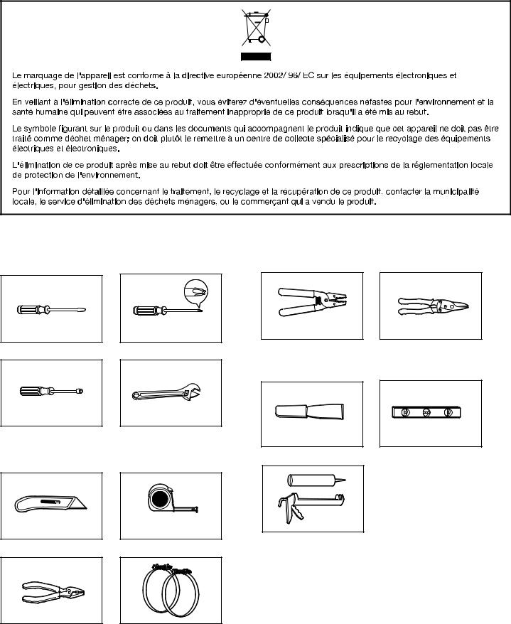
Outillage et Pièces
Rassembler les outils et piéces nécessaires avant de commancer l’installation.
Tournevis à lame plate
Tourne-écrou de 6,2 mm (1/4")
Couteau utilitaire
Tournevis Phillips no 2
Clé à molette avec ouverture jusqu’à 25 mm (1") ou clé à douille hexagonale (pour ajuster les pieds du sèche-linge)
Mètre ruban
Pince à dénuder les fils (pour les installations à raccordement direct)
Couteau à mastic
Pistolet à calfeutrage et composé de calfeutrage (pour l’installation
d’un nouveau circuit d’évacuation)
Cisaille de ferblantier (pour l’installation d’un nouveau conduit)
Niveau
Pince |
Brides de conduit |
22
 Loading...