


SEMI-PRO HE DRYERINSTALLATIONINSTRUCTIONS (original instructions)
Gas
INSTRUCTIONSD’INSTALATIOND’UN SECHE-LINGEHESEMI-PRO (traduction desinstructionsd’origine)
À gaz
INSTRUCCIONES DE INSTALACIÓN– SECADORAHE SEMI PROFESIONAL (traducción de las instruccionesoriginales)
A gas
ISTRUZIONI D’INSTALLAZIONE– ASCIUGATRICEHE SEMI-PRO (traduzione delle istruzioni originali)
A gas
INSTALLATIONSANLEITUNG FÜRDEN SEMI-PRO HE-WÄSCHETROCKNER(Übersetzung der Original-Bedienungsanleitung)
Gas
3LCGD9100 |
W10310126D |
|

TABLE OF CONTENTS
DRYER SAFETY ............................................................................ |
3 |
DRYER DISPOSAL ........................................................................ |
4 |
INSTALLATION REQUIREMENTS ............................................. |
4 |
Tools and Parts .......................................................................... |
4 |
Location Requirements ............................................................. |
4 |
Electrical Requirements - Gas Dryer.......................................... |
5 |
Gas Supply Requirements ....................................................... |
6 |
Venting Requirements ................................................................ |
7 |
INSTALLATION INSTRUCTIONS – GAS DRYER |
....................9 |
Install Leveling Legs.................................................................... |
9 |
Make Gas Connection................................................................ |
9 |
Connect Vent .............................................................................. |
9 |
Complete Installation ................................................................ |
9 |
MAINTENANCE INSTRUCTIONS .......................................... |
10 |
ASSISTANCE OR SERVICE .................................................... |
10 |
TECHNICAL SPECIFICATIONS – GAS DRYER...................... |
10 |
REVERSING THE DOOR SWING ........................................... |
11 |
ELECTRONIC CONTROL SETUP .......................................... |
13 |
TABLE DES MATIERES
SECURITE DU SECHE-LINGE ................................................ |
14 |
ELIMINATION DU SECHE-LINGE .......................................... |
15 |
EXIGENCES D’INSTALLATION................................................ |
15 |
Outillage et pièces .................................................................... |
15 |
Exigences d’emplacement ...................................................... |
16 |
Spécifications électriques - sèche-linge à gaz ...................... |
17 |
Spécifications de l’alimentation en gaz .................................. |
18 |
Exigences concernant l’évacuation .......................................... |
19 |
INSTRUCTIONS D’INSTALLATION – |
|
SECHE-LINGE A GAZ .............................................................. |
20 |
Installation des pieds de nivellement........................................ |
20 |
Raccordement à la canalisation de gaz .................................. |
21 |
Raccordement du conduit d’évacuation ................................ |
21 |
Achever l’installation ................................................................ |
21 |
INSTRUCTIONS D’ENTRETIEN............................................... |
21 |
ASSISTANCE OU SERVICE ..................................................... |
22 |
FICHE TECHNIQUE – SECHE-LINGE A GAZ ........................ |
22 |
INVERSION DU SENS D’OUVERTURE DE LA PORTE ......... |
23 |
REGLAGE DE LA CARTE |
|
DE CIRCUITS ELECTRONIQUES .......................................... |
25 |
ÍNDICE
SEGURIDAD DE LA SECADORA............................................ |
26 |
ELIMINACIÓN DE LA SECADORA ......................................... |
27 |
REQUISITOS DE INSTALACIÓN ............................................ |
27 |
Piezas y herramientas .......................................................... |
27 |
Requisitos de ubicación........................................................ |
27 |
Requisitos eléctricos - secadora a gas ................................ |
28 |
Requisitos del suministro de gas............................................ |
29 |
Requisitos de ventilación .................................................... |
30 |
INSTRUCCIONES DE INSTALACIÓN – |
|
SECADORA A GAS ................................................................ |
32 |
Instalación de las patas niveladoras .................................... |
32 |
Conexión del suministro de gas............................................ |
32 |
Conexión del ducto de escape ............................................ |
32 |
Complete la instalación ........................................................ |
32 |
INSTRUCCIONES DE MANTENIMIENTO .............................. |
33 |
AYUDA O SERVICIO TÉCNICO .............................................. |
33 |
ESPECIFICACIONES TÉCNICAS – SECADORA A GAS ...... |
33 |
CÓMO INVERTIR EL SENTIDO DE APERTURA |
|
DE LA PUERTA ....................................................................... |
34 |
PROGRAMACIÓN DEL CONTROL ELECTRÓNICO ............ |
36 |
INDICE
SICUREZZA DELL’ASCIUGATRICE ........................................ |
37 |
L’ELIMINAZIONE DELL’ASCIUGATRICE.................................. |
38 |
REQUISITI D’INSTALLAZIONE ................................................ |
38 |
Attrezzi e componenti............................................................. |
38 |
Requisiti di ubicazione ............................................................ |
38 |
Requisiti elettrici - asciugatrice a gas .................................... |
39 |
Requisiti di alimentazione del gas............................................ |
40 |
Requisiti di scarico ................................................................ |
41 |
ISTRUZIONI DI INSTALLAZIONE – ASCIUGATRICE |
|
A GAS ...................................................................................... |
43 |
Installazione dei piedini di regolazione .................................... |
43 |
Eseguire il colleganento gas .................................................... |
43 |
Connessione dello scarico ...................................................... |
43 |
Completamento dell’installazione............................................ |
44 |
ISTRUZIONI DI MANUTENZIONE ......................................... |
44 |
ASSISTENZA O MANUTENZIONE ......................................... |
45 |
DATI TECNICI – ASCIUGATRICE A GAS .............................. |
45 |
INVERSIONE DELLA ROTAZIONE DI APERTURA ............... |
46 |
CONFIGURAZIONE DEI CONTROLLI ELETTRONICI .......... |
48 |
INHALTSVERZEICHNIS
SICHERER BETRIEB DES WÄSCHETROCKNERS................ |
49 |
ENTSORGUNG DES WÄSCHETROCKNERS.......................... |
50 |
INSTALLATIONSVORAUSSETZUNGEN .................................. |
50 |
Werkzeug und Zubehör .......................................................... |
50 |
Standortvoraussetzungen ...................................................... |
50 |
Elektrische Voraussetzungen – Gasbetriebener Trockner...... |
51 |
Voraussetzungen für die Gasversorgung................................ |
52 |
Lüftungsvoraussetzungen ...................................................... |
53 |
2
INSTALLATIONSANLEITUNG – |
|
GASBETRIEBENER TROCKNER .......................................... |
55 |
Einsetzen der Stellbeine.......................................................... |
55 |
Die Gasverbindung herstellen ................................................ |
55 |
Anschluss der Abluftleitung .................................................... |
56 |
Abschluss der Installation ...................................................... |
56 |
WARTUNGSANLEITUNG ....................................................... |
56 |
REPARATURUND KUNDENDIENST .................................. |
57 |
TECHNISCHE DATEN – GASBETRIEBENER TROCKNER .... |
57 |
ÄNDERUNG DER TÜRÖFFNUNGSRICHTUNG ................... |
58 |
ELEKTRONISCHE REGELANLAGE ...................................... |
60 |

DRYER SAFETY
Your safety and the safety of others are very important.
many important safety messages in this manual and on your appliance. Always read and obey all safety
safety alert symbol.
alerts you to potential hazards that can kill or hurt you and others.
messages will follow the safety alert symbol and either the word “DANGER” or “WARNING.” mean:
 DANGER
 WARNING
You can be killed or seriously injured if you don't immediately follow instructions.
You can be killed or seriously injured if you don't follow instructions.
All safety messages will tell you what the potential hazard is, tell you how to reduce the chance of injury, and tell you what can happen if the instructions are not followed.
FOR YOUR SAFETY
1.Do not use or store petrol or other flammable materials in this appliance or near this appliance.
2.Do not spray aerosols in the vicinity of this appliance while it is in operation.
3.Do not modify this appliance.
WARNING: For your safety, the information in this manual must be followed to minimize the risk of •re or explosion, or to prevent property damage, personal injury, or death.
–Do not store or use petrol or other €ammable vapors and liquids in the vicinity of this or any other appliance.
–WHAT TO DO IF YOU SMELL GAS:
•Do not try to light any appliance.
•Do not touch any electrical switch; do not use any phone in your building.
•Clear the room, building, or area of all occupants.
•Immediately call your gas supplier from a neighbor's phone. Follow the gas supplier's instructions.
•If you cannot reach your gas supplier, call the •re department.
–Installation and service must be performed by a quali•ed installer, service agency, or the gas supplier.
3

DRYER DISPOSAL
INSTALLATION REQUIREMENTS
Tools and Parts
Gather the required tools and parts before starting installation. Read and follow the instructions provided with any tools listed here.
Tools needed:
■200 mm (8") or 250 mm (10") Pipe wrench
■200 mm (8") or 250 mm (10") Adjustable wrench
■Flat-blade screwdriver
■Phillips screwdriver
■Adjustable wrench that opens to 25 mm (1") or hex-head socket wrench
■Level
Parts supplied:
■8 mm (5/16") socket wrench
■Utility knife
■Vent clamps
■Pipe-joint compound resistant to LP gas
■Sealing gun and sealing compound (for installing new exhaust vent)
■Pliers
■Stiff-bladed putty knife
Remove parts bag from dryer drum. Check that all parts were included.
■Foot boot (4)
■Dryer foot (4)
NOTE: The circuit diagram for this dryer is located inside the lower front panel, within the Tech Sheets.
Location Requirements
If installing a gas dryer:
IMPORTANT: Observe all governing codes and ordinances.
■Check code requirements: Some codes limit or do not permit installation of clothes dryers in garages, closets, or sleeping quarters. Contact your local building inspector.
■Make sure that lower edges of the cabinet, plus the back and bottom sides of the dryer, are free of obstructions to permit adequate clearance of air openings for combustion air. See “Recessed Area and Closet Installation Instructions” below for minimum spacing requirements.
■Do not install on carpet.
NOTE: The dryer must not be installed in an area where it will be exposed to water and/or weather.
4

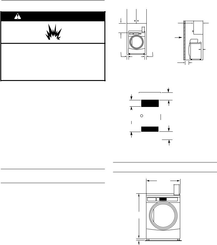
Recessed Area and Closet Installation Instructions
This dryer may be installed in a recessed area or closet. This dryer must not be installed behind a lockable door, a sliding door, or a door with a hinge on the opposite side to that of the dryer.
Theinstallation spacingis in millimetersandis theminimumallowable. Additional spacing should be considered for ease of installation, servicing, and compliance with local codes and ordinances.
If installed in a closet with a door, the minimum unobstructed air opening in the top and bottom is required. Louvered doors with equivalent air openings are acceptable.
The dryer must be exhausted outdoors.
No other fuel-burning appliance may be installed in the same closet as the dryer.
Minimum Installation Clearances
381 mm (15")
0 mm |
0 mm |
(0") |
(0") |
Recessed front view
356 mm (14") max
Closet door

 0 mm (0")

 25 mm (1")
Closet side view
Additional clearances for wall, door, and floor moldings may be required or if external exhaust elbow is used.
|
|
|
|
|
|
|
|
|
|
|
|
|
|
|
|
|
|
|
|
|
|
76 |
mm (3") |
||
|
|
|
|
|
|
|
|
|||||
310cm2* |
|
|
|
|
|
|
|
|
|
|
*Opening is the minimum |
|
|
|
|
|
|
|
|
|
|
|
|||
(48 in.2 ) |
|
|
|
|
|
|
|
|
|
|
for a closet door. Louvered |
|
|
|
|
|
|
|
|
|
|
|
doors with equivalent air |
||
|
|
|
|
|
|
|
||||||
|
|
|
|
|
|
|
|
|
|
|||
Front |
|
|
|
|
closet |
|
|
openings are acceptable. |
||||
|
|
|
|
|
|
|||||||
|
|
|
|
|
|
|
||||||
|
|
|
|
|
|
|||||||
view |
|
door |
|
|
|
|
|
|||||
|
|
|
|
|
|
|
|
|
|
|
|
|
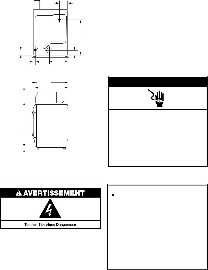
159 mm |
(61/4") |
ELECTRIC |
|
|
715 mm |
152 mm |
|
(281/8") |
|
89 mm |
|
(57/8") |
GAS |
(31/2") |
|
|
|
32 mm |
|
358 mm |
(11/4") |
|
(14") |
BACK VIEW
736 mm
(29") 695 mm (271/4")
203 mm (8")
921 mm (361/4")
|
|
|
|
|
|
|
|
|
|
|
|
|
|
|
|
|
|
|
|
|
|
25 |
|
mm |
|
SIDE VIEW |
||||||
|
|
|||||||||
|
|
|||||||||
(1") |
|
|
|
|
|
|
|
|||
155cm2* (24 in.2)
76 mm (3")
Product Dimensions 686 mm (27") dryer
686 mm
(27")
965 mm (38")
Electrical Requirements – Gas Dryer
Important: Observe all governing codes and ordinances.
You will need an earthed electrical outlet located within 610 mm (2 feet) of either side of the dryer.
|
|
|
|
|
|
|
|
|
|
|
|
|
|
|
|
|
|
|
|
|
|
|
|
25 |
|
mm |
|
|
|
FRONT VIEW |
5 |
||||
|
|
|
|
||||||||
|
|
|
|
||||||||
(1") |
|
|
|
|
|
|
|
|
|||

This dryer is supplied/fittedwithan electricity supplycordand plug. It should be connectedto electricitysupplysocketat the voltageshown on the rating plate.The minimumsupplyfusecapacity shouldbe 5A. The dryer must be positionedso thatthe plugis clearlyvisibleand accessible. This plug alsoprovidesthe function of an emergencystop control forthe user.If the fittedplug is notused, theelectricalconnection must be carried out bya competentelectricianinaccordancewithlocal ornationalcodes.
If the supply cord is damaged, it must be replaced with a specially terminated cord by an authorizedserviceagentor a similarlycompetent person in orderto avoid a hazard.
Do not use an adapter.
Do not use an extensioncord.
NOTE: In accordancewith theEuropeanEMCDirective(2004/108/EC), themaximumelectricity supplysystemimpedanceto whichthegas dryer should be connectedis declaredto be 0.054Ohm+ j0.034Ohm.
NOTE:Electrical safetystandards:The manufacturerhas chosencompliance withIEC/EN.60335 standardsas themostappropriateforthisproduct.
Using the universal cord included with this dryer:
The gas dryer is equipped with a universal cord with interchangeable plugs.
1.To use the universal cord, select the plug end that fits your electrical outlet, and plug it into the adapter on the supply cord.
2.Secure the plug end in place on the cord by aligning the 2 cover halves over the cord adapter and clipping them together.
Gas Supply Requirements
If codes permit and an additional earth bond wire is used, it is recommended that a qualified electrician determine that the earth bond path is adequate.
EARTHING INSTRUCTIONS
SAVE THESE INSTRUCTIONS
IMPORTANT: Observe all governing codes and ordinances.
Gas Supply
Before installation, check that the local gas distribution conditions, nature of gas and pressure, and the adjustment of the appliance are compatible. Burner information will be found on the model/serial rating plate in the door recess of the dryer. If this information does not agree with the type of gas available, see your dealer.
6
Natural Gas:
This dryer is factory adjusted for use with NATURAL GAS (G20), and no further adjustment should be required at installation.
L.P.Gas:
This dryer is also certified for use with L.P. (propane or butane) gases with appropriate conversion. No attempt shall be made to convert the appliance from the gas specified on the model/serial rating plate for use with a different gas without consulting the serving gas supplier.
Conversion must be done by a competent service technician. Gas conversion kit, part number W10233219, is available for purchase from your dealer. Full instructions are supplied with the kit.
Natural gas (France/Belgium):
This dryer is also certified for France/Belgium for use with G20/G25 gases (20 mbar/25 mbar) with appropriate conversion. No attempt should be made to convert this appliance from the gas specified on the gas rating label for use with a different gas without consulting the serving gas supplier.Gas conversion must be done by a qualified gas service technician. Conversion kit, part number (W10181947) is available for purchase from your dealer. Full instructions are supplied with the kit.
Supply line requirements:
Provide a rigid gas supply line to the dryer location. It should be minimum 12.5 mm (1/2") ID. When acceptable to the gas supplier and local codes, 10 mm (3/8") ID rigid supply line may be used for lengths under 6.1 m (20'). Pipe-joint compounds resistant to the action of L.P.gas must be used.
Gas connection to the dryer itself should be made by means of a flexible gas hose suitable for the appliance and gas category in accordance with national installation regulations. If in doubt, contact the gas supplier. It should be minimum 10 mm (3/8") ID.
A means of restraint should be used between the appliance and the wall to prevent straining of the rigid gas supply when the appliance is moved. An appropriate length of chain and a wall hook is recommended.
The dryer gas inlet connection is a 3/8" NPT thread. An adapter is supplied for conversion to standard ISO.228-1 thread (3/8" BSP).
Check for leaks by using an approved noncorrosive leakdetection solution. Bubbles will show a leak. Correct any leak found. A pressure measurement tapping is provided on the gas valve within the dryer, accessible after removal of the lower front panel.
The dryer must be disconnected from the gas supply piping system during any pressure testing of that system.
Venting Requirements
 WARNING
Fire Hazard
Use a heavy metal vent.
Do not use a plastic vent.
Do not use a metal foil vent.
Failure to follow these instructions can result in death or fire.
WARNING: To reduce the risk of fire, this dryer MUST BE EXHAUSTED OUTDOORS.
■Following theseventingrequirementswillminimiseducting air noise.
■Gas dryers should only be installed in a room if the room meets the appropriate ventilation requirements specified in the national installation regulations. Make sure the room containing the dryer has an adequate air supply for gas combustion and drying operation. A window or equivalent means of ventilation must be opened in the room when the dryer is in use (an equivalent form of opening includes an
adjustable louver, hinged panel, or other means of ventilation that opens directly to outside air). Adequate ventilation has to be provided to avoid the backflow of gases into the room from other fuel-burning appliances, including open fires (i.e. available airflow into the room should match airflow out from the room).
■Thedesign of thefluesystemshouldbe suchthatanycondensate formedwhenoperatingthedryerfromcoldshalleitherbe retained and subsequentlyre-evaporatedor discharged.Followingthese instructions should adequatelymeet this requirement.
■The dryer vent must not be discharged into a flue which
is used for exhausting fumes from appliances burning gas or other fuels, chimney, wall, ceiling, or a concealed space of a building, or any other vent used for venting.
■Do not use an exhaust hood with a magnetic latch.
■Do not install flexible metal vent in enclosed walls, ceilings, or floors.
■102 mm (4") heavy metal vent and clamps must be used.
■Use clamps to seal all joints. Vent must not be connected or secured with screws or other fastening devices which extend into the interiorof the vent and catchlint. Do not use duct tape.
IMPORTANT: Observe all governing codes and ordinances. Use a heavy metal vent. Do not use plastic or metal foil vent. Rigid metal vent is recommended to avoid crushing and kinking.
Flexible metal vent must be fully extended and supported when the dryer is in its final position. Remove excess flexible metal vent to avoid sagging and kinking that will result in reduced airflow and poor performance.
An exhaust hood should cap the vent to keep rodents and insects from entering the building.
Exhaust hood must be at least 305 mm (12") from the ground or any object that may be in the path of the exhaust (such as flowers, rocks, or bushes).
If using an existing vent system, clean lint from the entire length of the system and make sure exhaust hood is not plugged with lint. Replace any plastic or metal foil vent with rigid metal or flexible metal vent.
7

Plan installation to use the fewest number of elbows and turns.
A B
Exhaust Air Flow
A.Good
B.Better
Allow as much room as possible when using elbows or making turns. Bend vent gradually to avoid kinking.
Vent outlet is located at the center of the bottom dryer back.
The vent can be routed up, down, left, right, behind the dryer, or straight out the back of the dryer.
Vent System Length
Maximum length of vent system depends upon the type of vent used, number of elbows, and type of exhaust hood.
Maximum Vent Length
102 mm (4") Exhaust Hoods
|
Box |
Louvered |
64 mm (21⁄2") Angled |
Rigid Metal Vent |
|
|
|
No. of 90° turns |
Box Hood and Louvered Style |
Angled Hood Style |
|
0 |
39.6 m (130 ft.) |
39.3 m (129 ft.) |
|
1 |
38.1 m (125 ft.) |
36.3 m (119 ft.) |
|
2 |
35.1 m (115 ft.) |
33.2 m (109 ft.) |
|
3 |
32.3 m (106 ft.) |
30.5 m (100 ft.) |
|
4 |
98 m |
(98 ft.) |
28 m (92 ft.) |
If dryer is installed in a confined area, such as a bedroom, bathroom, or closet, provision must be made for enough air for combustion and ventilation. (Check governing codes and ordinances.) See “Recessed Area and Closet Installation Instructions” in the “Location requirements” section.
A 102 mm (4") outlet hood is preferred. However,a 64 mm (21⁄2") outlet exhaust hood may be used. A 64 mm (21⁄2") outlet creates greater back pressure than other hood types.
For permanent installation, a stationary vent system is required.
Multiple Dryer Venting
■A main vent can be used for venting a group of dryers. Main vent should be sized to remove 5663 l/min (200 CFM) of air per dryer. Large-capacity lint screens of proper design may be used in the main vent if checked and cleaned frequently. The room where the dryers are located should have make-up air equal to or greater than the airflow of all the dryers in the room.
■A back-draft damper kit is needed and is available from a laundry distributor; it should be installed in the vent of each dryer to keep exhausted air from returning into the dryers and to keep the exhaust in balance within the main vent. Unobstructed return air openings are required.
Each vent should enter the main vent at an angle pointing in the direction of the airflow. Vents entering from the opposite side should be staggered to reduce the exhausted air from interfering with the other vents.
The maximum angle of each vent entering the main vent should be no more than 30°.
A
 air !ow B
A.Individual dryer vent
B.Main vent
Keep air openings free of dry cleaning fluid fumes. Fumes create acids which, when drawn through the dryer heating units, can damage dryers and items being dried.
A clean-out cover should be located on the main vent for periodic cleaning of the vent system.
If an exhaust hood cannot be used:
B

 A D
A D
C
12" min.
(305 mm)
Min. 300 mm (12") clearance above any accumulation
of snow, ice, or debris such as leaves.
A.Exhaust hood or elbow
B.Wall
C.Main collector vent
D.Horizontal vent
E.180° sweep elbow
F.Vertical vent
G.Roof
 E
E
610 mm (24")
min. above
24" min.
(610 mm) F
highest point of building
G

 C
C
The outside end of the main vent should have a sweep elbow directed downward. If the main vent travels vertically through the roof, rather than through the wall, install a 180° sweep elbow on the end of the vent at least 610 mm (2 ft.) above the highest part of the building. The opening in wall or roof shall have a diameter 13 mm (1⁄2") larger than the vent diameter. The vent should be centered in the opening.
Do not install screening or cap over the end of the vent.
8

INSTALLATION INSTRUCTIONS – GAS DRYER
Install Leveling Legs |
Connect Vent |
|
NOTE: Slide dryer onto cardboard or hardboard before moving to avoid damaging floor covering.
1.Using two or more people, move dryer to desired installation location.
2.Take tape off front corners of dryer. Open dryer and remove the literature and parts packages. Wipe the interior of the drum thoroughly with a damp cloth.
3.Take two of the cardboard corners from the carton and place them on the floor in back of the dryer. Firmly grasp the body of the dryer and gently lay it on its back on the cardboard corners.
4.With one of the legs in hand, check the ridges for a diamond marking. That’s how far the leg is supposed to go into the hole.
5.Start to screw the leveling legs into the holes by hand. (Use a small amount of liquid detergent to lubricate the screw threads so it is easier to turn the legs.) Use a 1" (25 mm) wrench or socket wrench to finish turning the legs until you reach the diamond mark. Then fit a protective foot boot over each foot.
6.Now stand the dryer up.
7.Remove cardboard or hardboard from under dryer. Adjust the legs of the dryer up or down until the dryer is level.
Make Gas Connection
1.Remove red cap from gas pipe.
2.Connect gas supply to dryer. If the flexible gas hose has 3/8" BSP thread, use the supplied conversion thread adapter. Use pipe-joint compound resistant to the action of L.P.gas for gas connections.
If necessary for service, open the toe panel. Use a putty knife to press on the 2 toe panel locks located at the top of the toe panel. Pull downward on the toe panel to open. Toe panel is hinged at the bottom.
3.Open the shutoff valve in the gas supply line.
4.Test all connections by brushing on an approved noncorrosive leak-detection solution. Bubbles will show a leak. Correct any leaks found.
1.Using a 102 mm (4") clamp, connect vent to exhaust outlet in dryer. If connecting to existing vent, make sure the vent is clean. The dryer vent must fit over the dryer exhaust outlet and inside the exhaust hood. Make sure the vent is secured to exhaust hood with a 102 mm (4") clamp.
2.Move dryer into final position. Do not crush or kink vent. Make sure dryer is level.
3.Check to be sure there are no kinks in the flexible gas line.
Complete Installation
1.With dryer in final position place level on top of the dryer, first side to side; then front to back. If the dryer is not level, adjust the legs of the dryer up or down until the dryer is level.
 WARNING
Electric Shock Hazard This dryer must be earthed.
Securely tighten all electrical connections.
Failure to do so can result in death, fire, or electric shock.
2.Plug into an earthed outlet.
3.Check dryer operation:
Press the selection button for a full cycle and let the dryer run for at least five minutes. Dryer will stop when time is used up.
NOTE: Dryer door must be closed for dryer to operate. When door is open, dryer stops, but timer continues to run. To restart dryer, close door and press a cycle button.
4.If the burner does not ignite and there is no heat inside the dryer, shut off dryer for five minutes. Check that all gas supply valves are in the “ON” position and that the electrical cord is plugged in. Repeat five-minute test.
9
MAINTENANCE INSTRUCTIONS
Maintenance instructions:
■Clean lint screen after each cycle.
■Removing accumulated lint (disconnect dryer from electricity and gas supplies before starting this task):
•From inside the dryer cabinet:
Lint should be removed every2 yearsor more often,depending on dryer usage.Cleaningshould be done by a qualifiedperson.
•From the exhaust vent:
Lint should be removed every 2 years, or more often, depending on dryer usage.
If dryer does not operate, check the following:
■Electric supply is connected.
■Circuit breaker is not tripped or fuse is not blown.
■Door is closed. Listen closely to hear door switches activate.
■Selected cycle button has been pressed firmly and display shows cycle time.
■Check that gas supply shutoff valves are set in open position.
ASSISTANCE OR SERVICE
If you need further assistance, you can contact the dealer/ distributor where the dryer was purchased.
When you call, you will need the dryer model number and serial number. Both numbers can be found on the serial-rating plate located on your dryer.
For Warranty Terms and Conditions, contact the dealer/distributor.
TECHNICAL SPECIFICATIONS - GAS DRYER
220-240V~50Hz1ph 3A max. IP24 Clothes capacity:9.0 kg max. Sound pressure level, Lpa: 58 dBA (uncertainty, Kpa: +/–10 dBA) Total mass: 68 kg max.
Factory set for NATURAL GAS: Injector size: 2.2 mm Heat input gross: 5.9 kW
European Country: |
CH, CZ, CY, ES, GB, GR, HR, |
|
CY, CZ, DK, EE, FI, GR, HU, IT, |
|
IE, IT, PT, SI, SK, TR |
|
NO, RO, SE, SK, TR |
European Gas Category: |
II2H3+ |
|
II2H3B/P |
Gas Flow Rate: |
0.562703 m3/hr |
|
0.562703 m3/hr |
Supply Pressure (G20): |
20 mbar |
|
20 mbar |
|
|
|
|
Factory Adjusted Pressure: |
7.4 mbar |
|
7.4 mbar |
|
|
|
|
With LP Gas Conversion Kit: Injector size: 1.25 mm Heat input gross: 6.4 |
kW |
||
|
|
|
|
European Country: |
CH, CZ, CY, ES, GB, GR, HR, |
|
CY, CZ, DK, EE, FI, GR, HU, IT, |
|
IE, IT, PT, SI, SK, TR |
|
NO, RO, SE, SK, TR |
|
|
|
|
European Gas Category: |
II2H3+ |
|
II2H3B/P |
Butane Supply Pressure (G30): |
28-30 mbar |
|
30 mbar |
Adjusted Pressure: |
N/A |
|
N/A |
|
|
|
|
Propane Supply Pressure (G31): |
37 mbar |
|
30 mbar |
Adjusted Pressure: |
N/A |
|
N/A |
|
|
|
|
With France/Belgium NATURAL GAS conversion kit: Injector size: 1.65 mm |
Heat input gross: 5.9 kW |
||
European Country: |
FR, BE |
||
|
|
||
European Gas Category: |
I2E+ |
||
Supply Pressure (G20): |
20 mbar |
||
|
|
||
Supply Pressure (G25): |
25 mbar |
||
Adjusted Pressure: |
N/A |
|
|
|
|
|
|
NOTE: Conversion kit: From Natural Gas to LP Gas: Whirlpool Part No. W10233219.
Conversion kit: From Natural Gas to Natural Gas - France/Belgium: Whirlpool Part No. W10184947. Manufacturer: Whirlpool Corporation, Benton Harbor, Michigan 49022, USA.
EU representatives: Whirlpool UK Ltd, Croydon, CR9 4RY, UK.
& Bauknecht Hausgeräte GmbH, D-73614 Schorndorf, Germany
10
REVERSING THE DOOR SWING
Door swing can be changed from a right-side opening to left-side opening, if desired.
Place a towel or soft cloth on top of the dryer or work space to avoid damaging the surface.
Remove the Door Assembly
1.Remove 3 of the 4 screws that hold the door hinge on the front panel of the dryer. Partially loosen the remaining screw with keyhole opening and lift the door off the screw.
 A.
A.
Loosen  screw
screw
with 
 keyhole
  opening
B.
A.Dryer front panel
B.Door assembly
2.Lay the door assembly on a previously prepared flat surface with the inside (inner door assembly) facing up.
3.Remove the 6 Phillips head screws to release the outer door assembly from the inner door assembly, as indicated below. See illustration. It is important that you remove only the 6 indicated screws.
5. Rotate outer door 180°.
Reverse Hinge
1.Use a small flat-blade screwdriver to remove 2 plug strips from the inner door. Slide the head of the screwdriver under the plugs, being certain not to scratch the inner door surface. Lift up.
2.Remove the 4 screws that attach to the inner door hinge and move the hinge to the other side. Reinstall the 4 screws.
4. Lift the inner door assembly off the outer door assembly.
Door hinge
3.Reinstall plug strips on opposite side of the inner door.
4.Check for fingerprints on the glass. Clean glass if necessary.
11

5.Place the inner door assembly inside the outer door assembly. To fit correctly,the inner door assembly edge fits completely inside the outer door assembly edge.
6.Reassemble the inner and outer door assemblies with the 6 screws.
Reverse the strike
1.Use a small flat-blade screwdriver to remove plug strip from the dryer door opening. Slide the head of the screwdriver under the plugs, being certain not to scratch the dryer surface. Lift the plastic strip from the dryer slowly to avoid distortion of the plug strip.
 B.
B.
 A.
A.
A.Plug strip
B.Door strike
2. Remove the strike using a Phillips screwdriver.
3. Insert strike on the opposite side.
Reinstall the door
1.Reattach door to dryer front panel with the 4 screws. Partially install the screw with keyhole opening first, and fit the keyhole opening in the hinge over the screw. Then install the remaining 3 screws and tighten all 4 screws.
 A.
A.
Install this 
 screw first
B.
A.Dryer front panel
B.Door assembly
2.Check for fingerprints on the glass. Clean glass if necessary.
3.Close door and check that it latches securely.
12

ELECTRONIC CONTROL SETUP
IMPORTANT
Electrostatic Discharge (ESD)
Sensitive Electronics
ESD is present everywhere. ESD may damage or weaken the electronic control assembly. The new control assembly may appear to work well after repair is finished, but failure may occur at a later date due to ESD stress.
■Use an anti-static wrist strap. Connect wrist strap to green earth connection point or unpainted metal in the appliance.
-OR-
Touch your finger repeatedly to a green earth connection point or unpainted metal in the appliance.
■Before removing the part from its package, touch the anti-static bag to a green earth connection point or unpainted metal in the appliance.
■Avoid touching electronic parts or terminal contacts; handle electronic control assembly by edges only.
■When repackaging failed electronic control assembly in anti-static bag, observe above instructions.
GENERAL USER INFORMATION
“out of order” showing in display
This condition indicates the dryer is inoperative. Diagnostic or failure code will follow the scrolling message.
‘0 Minutes’ showing in display
This condition indicates the dryer cannot be operated until normal operation is restored by opening and closing the door. If a door switch fails, it must be replaced before normal operation can be restored.
Cold Start (initial first use)
Dryer is programmed at the factory as follows: ■ 45 minutes dry time.
Warm Start (after power failure)
A few seconds after power is restored, if a cycle was in progress at the time of the power failure, ‘RESELECT CYCLE’ will flash
in the display. This is to indicate the need for a fabric setting button to be pressed to restart dryer.
Dryer is pre-set for free cycle operation so it can be run without payment.
DISPLAY
After the dryer has been installed and plugged in, the display will show ‘0 minutes.’
Once the dryer has been plugged in and the dryer door opened and closed, the display will flash ‘SELECT CYCLE’.
EU - DECLARATION OF CONFORMITY
CE - DECLARATION DE CONFORMITE
BAUKNECHT HAUSGERÄTE GmbH, D-73614 Schorndorf representing (représentant): WHIRLPOOL EUROPE S.r.l I-21025 COMERIO
declare under our sole responsibility that the product déclarons sous notre propre responsabilité que le produit
dryer
(sèche-linge) :
Whirlpool 3LCGD9100
to which this declaration relates is in conformity with the following standard(s) or other normative document(s)
auquel se référe cette déclaration est conforme aux normes suivantes ou autres documents normatifs
EN 60335-1:2002+A1+A2+A11+A12+A13
EN 60335-2-11:2003+A1+A2
EN 12752-1:1999
EN 62233:2008
EN ISO 10472-1:2008
EN ISO 10472-4:2008
EN 55014-1:2006
EN 55014-2:1997+A1:2001
EN 61000-3-11:2000
EN 61000-3-12:2005
following the provisions of Directive(s): suivant les prévisions des Directives :
2009/142/EC EUROPEAN GAS APPLIANCE DIRECTIVE 2006/95/EC LOW VOLTAGE DIRECTIVE (CEE Directive Basse Tension)
2004/108/EC ELECTROMAGNETIC COMPATIBILITY DIRECTIVE (CEE Directive Compatibilité Electro-magnétique)
2006/42/EC MACHINERY DIRECTIVE
|
represented by |
Schorndorf, 29.04.2010 |
Roberto Mottura |
Place and date: |
Director PDC, FC |
lieu et date : |
|
Name and signature of authorised person |
13 |
|
Nom et signature de la personne autorisée |
||
|

SECURITE DU SECHE-LINGE
Votre sécurité et celle des autres est très importante.
Nous donnons de nombreux messages de sécurité importants dans ce manuel et sur votre appareil ménager. Assurez-vous de toujours lire tous les messages de sécurité et de vous y conformer.
Voici le symbole d’alerte de sécurité.
Ce symbole d’alerte de sécurité vous signale les dangers potentiels de décès et de blessures graves à vous et à d’autres.
Tous les messages de sécurité suivront le symbole d’alerte de sécurité et le mot “DANGER” ou “AVERTISSEMENT”. Ces mots signifient :
AVERTISSEMENT
Risque possible de décès ou de blessure grave si vous ne suivez pas immédiatement les instructions.
Risque possible de décès ou de blessure grave si vous ne suivez pas les instructions.
Tous |
de sécurité vous diront quel est le danger potentiel et vous disent comment réduire le risque de blessure et |
ce qui |
se produire en cas de non-respect des instructions. |
POUR VOTRE SECURITE
1.Ne pas utiliser ou remiser d’essence ou autres matériaux inflammables dans cet appareil ménager ou à proximité de celui-ci.
2.Ne pas vaporiser d’aérosols à proximité de cet appareil ménager lorsqu’il est en fonctionnement.
3.Ne pas modifier cet appareil ménager.
AVERTISSEMENT : Pour votre sécurité, les renseignements dans ce manuel doivent être observés pour réduire au minimum les risques d’incendie ou d’explosion ou pour éviter des dommages au produit, des blessures ou un décès.
–Ne pas entreposer ou utiliser de l’essence ou d’autres vapeurs ou liquides inflammables à proximité de cet appareil ou de tout autre appareil électroménager.
–QUE FAIRE DANS LE CAS D’UNE ODEUR DE GAZ :
•Ne pas tenter d’allumer un appareil.
•Ne pas toucher à un commutateur électrique; ne pas utiliser le téléphone se trouvant sur les lieux.
•Évacuer tous les gens de la pièce, de l’édifice ou du quartier.
•Appeler immédiatement le fournisseur de gaz d’un téléphone voisin. Suivre ses instructions.
•À défaut de joindre votre fournisseur de gaz, appeler les pompiers.
–L’installation et l’entretien doivent être effectués par un installateur qualifié, une agence de service ou le fournisseur de gaz.
14

ELIMINATION DU SECHE-LINGE
EXIGENCES D’INSTALLATION
Outillage et pièces
Rassembler les outils et pièces nécessaires avant de commencer l’installation. Lire et respecter les instructions d’installation fournies avec chacun des outils de cette liste.
Outillage nécessaire
■Clé à tube de 200 mm (8") ou 250 mm (10")
■Clé à molette de 200 mm (8") ou 250 mm (10")
■Tournevis à lame plate
■Tournevis Phillips
■Clé à molette avec ouverture jusqu’à 25 mm (1") ou clé à douille hexagonale
■Niveau
■Clé à douille de 8 mm (5/16")
■Couteau utilitaire
■Brides de fixation
■Composé d’étanchéité des raccords filetés - résistant au propane
■Pistolet à calfeutrage et composé de calfeutrage (pour l’installation d’un nouveau circuit d’évacuation)
■Pince
■Couteau à mastic à lame rigide
Pièces fournies
Retirer le sac de pièces du tambour du sèche-linge. Vérifier la présence de toutes les pièces.
■Patin (4)
■Pied du sèche-linge (4)
NOTE : Le schéma de circuits de ce sèche-linge se trouve
à l’intérieur du panneau inférieur avant, dans les fiches techniques.
15
Exigences d’emplacement
AVERTISSEMENT
Garder les matières et |
inflammables, telle |
que l'essence, loin de |
. |
Ne pas installer dans un garage. |
|
Le non-respect de ces instructions peut causer un décès, une explosion ou un incendie.
Pour l’installation d’un sèche-linge à gaz :
IMPORTANT : Respecter les dispositions de tous les codes et règlements en vigueur.
■Déterminer les exigences des codes : Certains codes limitent ou prohibent l’installation d’un sèche-linge dans un garage, un placard, ou une chambre à coucher. Consulter l’inspecteur local des bâtiments.
■Veiller à ce que les bords inférieurs de la caisse ainsi que l’arrière et les côtés inférieurs du sèche-linge soient exempts d’obstructions, afin de permettre le passage adéquat de l’air de combustion. Voir la section “Instructions d’installation dans un placard ou un encastrement”pour l’espace de dégagement minimal.
■Ne pas installer sur un tapis.
NOTE : Le sèche-linge ne doit pas être installé en un endroit où il serait exposé à de l’eau ou aux intempéries.
Instructions pour l’installation dans un placard ou un encastrement
Ce sèche-linge peut être installé dans un placard ou un encastrement. Ce sèche-linge ne doit pas être installé derrrière une porte verrouillable, coulissante, ou une porte avec charnière du côté opposé de l’emplacement de celle du sèche-linge.
Les distances de séparation sont exprimées en millimetre; il s’agit des distances minimales. Il est utile de prévoir des
distances de séparation supérieures pour faciliter l’installation et les travaux d’entretien, ou si ceci est exigé par les codes et règlements locaux.
Si la porte du placard est installée, on doit respecter la taille minimale des ouvertures d’entrée d’air au sommet et en bas. On peut utiliser une porte à jalousies offrant une surface de passage d’air équivalente.
Le circuit d’évacuation du sèche-linge doit être relié à l’extérieur.
Aucun autre appareil utilisant un combustible ne doit être installé dans le même placard.
Distances de séparation minimales
|
|
356 mm |
381 mm |
|
(14") max |
(15") |
|
|
|
|
Porte du |
|
|
placard |
0 mm |
0 mm |
|
(0") |
(0") |
0 mm |
|
|
(0") |
|
|
25 mm (1") |
Encastrement, vue avant |
Placard, vue latérale |
On doit prévoir un espacement additionnel pour tenir compte éventuellement des moulures du mur, de la porte et du plancher, ou si le circuit d’évacuation comporte un coude.
310cm2* (48 in.2 )
vue |
|
|
Porte du |
|
|||
avant |
placard |
||
|
|
|
|
155cm2* (24 in.2)
76 mm (3")
*Taille minimale de l’ouverture pour la porte du placard. On peut utiliser une porte à claire-voie offrant une surface de passage d’air équivalente.
76 mm (3")
Dimensions du produit – Sèche-linge de 686 mm (27")
686 mm
(27")
965 mm (38")
25 mm
(1") VUE AVANT
16
152 mm (57/8")
159 mm |
(61/4") |
CÂBLE |
ÉLECTRIQUE |
715 mm (281/8")
CANALISATION
DE GAZ 89 mm (31/2")
32 mm |
358 mm |
(11/4") |
(14") |
VUE ARRIÈRE
736 mm
(29") 695 mm (271/4")
203 mm (8")
921 mm (361/4")
|
|
|
|
|
|
|
|
|
|
|
|
|
|
|
|
|
|
|
|
|
|
25 |
|
mm |
VUE LATÉRALE |
|||||||
|
||||||||||
|
||||||||||
(1") |
|
|
|
|
|
|
|
|||
Spécifications électriques - sèche-linge à gaz
Important: Se conformer à tous les codeset règlements en vigueur.
Une prise électrique avec liaison à la terre située à 610 mm (2 pi) maximum de l’un des côtés du sèche-linge est nécessaire.
Ce sèche-linge est équipéd’un cordon d’alimentation électrique et d’unefiche.Il doit êtreconnectéà une priseélectriquede tensiontel qu’indiqué sur la plaquesignalétique.La capacitéminimaledu fusible d’alimentation doit être de 5A. Le sèche-lingedoitêtreinstalléde façonà ce que la fiche soitclairementévidenteet accessible.Cette fiche remplit égalementla fonctionde commanded’arrêtd’urgence pourl’utilisateur.Si la fiched’originen’estpas utilisée,la connexion électrique doit êtreeffectuéepar un électriciencompétent conformémentaux codeslocaux et nationaux.Si le cordon d’alimentation est endommagé,il doitêtreremplacépar un cordonà emboutspécifique par un agentd’entretienautoriséou une personne de compétencesimilaireafind’éviter tout danger.
Ne pas utiliser d’adaptateur.
Ne pas utiliser de câble de rallonge.
NOTE : Conformément à la directive européenne CEM (2004/108/EC), l’impédance maximale du système d’alimentation électrique auquel le sèche-linge à gaz doit être connecté est
de 0,054 Ohm + j0,034 Ohm.
NOTE : Normes de sécurité électriques : Pour ce produit, le fabricant a estimé que la mise en conformité avec les normes IEC/EN.60335 était la plus appropriée.
 AVERTISSEMENT
Risque de choc électrique
Une mise à la terre est nécessaire sur ce sèche-linge.
Ne pas utiliser une tuyauterie de gaz pour le raccordement à la terre.
Ne pas changer la •che du cordon d’alimentation. Si elle ne correspond pas à la prise de sortie, faire
installer une prise adéquate par un électricien quali•é.
Ne pas utiliser de câble de rallonge avec ce sèche-linge.
Le non-respect de ces instructions peut causer un décès, un incendie ou des blessures graves.
Si les codes le permettent et si un conducteur supplémentaire de mise à la terre est utilisé, il est recommandé qu’un électricien qualifié inspecte le parcours du fil de mise à la terre.
INSTRUCTIONS DE MISE A LA TERRE
Ce sèche-linge a été conçu pour être raccordé au
secteur et mis à la terre ; la mise à la terre est donc impérative: En cas disfonctionnement ou de panne, la mise à la terre réduira le risque de choc électrique en offrant au courant électrique une voie de moindre résistance. Ce sèche-linge
est alimenté par un cordon électrique comportant un conducteur de liaison à la terre et une •che de mise à la terre. La •che doit être branchée sur une prise de courant appropriée correctement installée et reliée à la terre conformément à tous les codes et règlements locaux.
AVERTISSEMENT : Un raccordement inapproprié du conducteur de liaison à la terre peut causer un risque de choc électrique. En cas de doute concernant la qualité
de la liaison à la terre du sèche-linge, consulter un électricien quali•é, un agent ou personnel d’entretien. Ne pas modi•er la •che fournie avec ce sèche-linge : Si elle ne correspond pas à la prise de sortie, faire installer une prise appropriée
par un électricien quali•é.
CONSERVEZ CES INSTRUCTIONS
17

À l’aide du cordon universel fourni avec ce sèche-linge :
Ce sèche-linge à gaz est équipé d’un cordon universel avec des fiches interchangeables.
1.Pour utiliser le cordon universel, sélectionner la fiche amovible qui correspond à votre prise de courant et brancher dans l’adaptateur placé sur le cordon d’alimentation.
2.Fixer la fiche amovible sur le cordon en alignant les deux moitiés de couvercle sur l’adaptateur et en les emboîtant.
Spécifications de l’alimentation en gaz
AVERTISSEMENT
Risque d'explosion
Connecter ce sèche-linge à une canalisation d’alimentation en gaz réglementée. La pression
de gaz doit être conforme aux exigences techniques (voir dernière page).
Installer un robinet d'arrêt.
Bien serrer tous les raccords de la ligne de gaz.
En cas de connexion au gaz propane, demander à une personne quali•ée de s'assurer que la pression d’alimentation en gaz est correcte.
Le non-respect de ces instructions peut causer un décès, une explosion ou un incendie.
IMPORTANT : Se conformer à tous les codes et réglements en vigueur.
Alimentation en gaz
Avant d’effectuer l’installation, vérifier que les caractéristiques de distribution, la nature et la pression de gaz locales ainsi que le réglage de l’appareil sont compatibles. Les informations
concernant le brûleur se trouvent sur la plaque signalétique située sur la paroi interne de la porte du sèche-linge. Si l’information ne correspond pas au type de gaz disponible, consulter votre revendeur.
Gaz naturel :
Ce sèche-linge est configuré en usine pour une utilisation au GAZ NATUREL (G20) et aucun réglage supplémentairen’est nécessaire lors de l’installation.
Gaz propane :
Ce sèche-linge est également homologué pour une utilisation avec des gaz de pétrole liquéfié (propane ou butane) après conversion appropriée. Ne pas tenter de convertir l’appareil pour une utilisation avec un gaz différent de celui indiqué sur la plaque signalétique sans consulter le fournisseur de gaz au préalable.
La conversion doit être effectuée par un réparateur qualifié. La trousse de conversion, numéro de référence W10233219, est disponible à l’achat chez votre revendeur.Des instructions accompagnent cette trousse.
Gaz naturel (France/Belgique) :
Ce sèche-linge est également homologué par la France/Belgique pour une utilisation avec un gaz G20/G25 (20 mbar/25 mbar) avec une conversion appropriée. Il ne faut pas essayer de convertir ce sèche-linge à partir du gaz indiqué sur l’étiquette d’indice de gaz vers un gaz différent sans consulter le fournisseur de gaz. La conversion d’un gaz à un autre doit être faite par
un technicien qualifié de service de gaz. L’ensemblede conversion (numéro de pièce W10181947) peut être acheté chez votre marchand. Des instructions complètes sont fournies avec l’ensemble.
Exigences concernant le conduit d’alimentation :
Installer un conduit rigide d’alimentation en gaz à l’emplacement du sèche-linge. Le diamètre interne minimal du conduit doit être de 12,5 mm (1/2"). Lorsque les codes locaux et votre fournisseur de gaz l’autorisent, un diamètre interne de conduit rigide de
10 mm (3/8") peut être utilisé pour des longueurs inférieures à 6,1 m (20 pi.). Une pâte d’étanchéité pour joints résistant à l’action du gaz propane doit être utilisée.
Le raccordement au gaz du sèche-linge lui-même doit être effectué au moyen d’un conduit de gaz flexible qui convienne à l’appareil et corresponde à la catégorie de gaz, conformément aux règlements d’installation nationaux. En cas de doute, contacter le fournisseur de gaz. Le diamètre interne doit être d’au moins 10 mm (3/8").
Un dispositif de fixation doit être installé entre l’appareil et le mur afin d’éviter que la canalisation d’alimentation en gaz rigide ne subisse de tension lors d’un déplacement de l’appareil. Il est recommandé d’utiliser une longueur de chaîne appropriée et un crochet mural.
Le raccord du conduit d’alimentation en gaz du sèche-linge est un filetage conique NPT de 3/8". Un adaptateur est fourni pour la conversion à un filetage standard (3/8" BSP) selon la norme ISO.228-1.
Vérifier l’absence de fuites en utilisant une solution de détection non-corrosive homologuée. L’apparitionde bulles indique la présence d’une fuite. Réparer toute fuite éventuelle. Un dispositif de mesure de la pression est fourni avec le robinet de gaz à l’intérieur du sèche-linge; on peut y accéder après avoir retiré
le panneau avant inférieur.
Le sèche-linge doit être déconnecté du système d’alimentation en gaz lors de tout test de pression.
18
 Loading...