


TRENDnet User’s Guide |
|
|
Contents |
|
|
1. Introduction ................................................................................ |
1 |
|
1.1 Introduction of the management functions............................................................. |
1 |
|
1.2 |
General Features...................................................................................................... |
2 |
1.3 |
Layer-2 Switching..................................................................................................... |
3 |
1.4 |
Multicast.................................................................................................................. |
3 |
1.5 |
Carrier Ethernet ....................................................................................................... |
3 |
1.6 |
Quality of Service ..................................................................................................... |
3 |
1.7 |
Security .................................................................................................................... |
3 |
1.8 |
Standard References ................................................................................................ |
3 |
1.9 |
Front Panel LEDs Indicators ..................................................................................... |
4 |
1.10 Rear Panel Connectors........................................................................................... |
4 |
|
2. Hardware Installation.................................................................. |
5 |
|
2.1 Unpacking ................................................................................................................ |
5 |
|
2.2 |
Switch Installation ................................................................................................... |
5 |
2.3 Adding Module ........................................................................................................ |
5 |
|
3. Console ....................................................................................... |
5 |
|
3.1 |
Console Setup........................................................................................................... |
5 |
3.2 |
Login ........................................................................................................................ |
6 |
4. Configuring with WEB.................................................................. |
6 |
|
4.1 |
Login ........................................................................................................................ |
7 |
4.2 Web Menus.............................................................................................................. |
7 |
|
4.3 |
Configuration ....................................................................................................... |
8 |
|
4.3.1 System......................................................................................................... |
8 |
|
4.3.1.1 Information.............................................................................................. |
8 |
|
4.3.1.2 IP .............................................................................................................. |
8 |
|
4.3.1.3 NTP......................................................................................................... |
10 |
|
4.3.1.4 Time ....................................................................................................... |
10 |
|
Table of Contents |
4.3.1.5 Log ......................................................................................................... |
12 |
4.3.2 Green Ethernet ......................................................................................... |
12 |
4.3.2.1 Port Power Savings ................................................................................ |
12 |
4.3.3 Port ........................................................................................................... |
13 |
4.3.4 DHCP ......................................................................................................... |
15 |
4.3.4.1 Server-Mode.......................................................................................... |
15 |
4.3.4.2 Server-Excluded IP ................................................................................. |
15 |
4.3.4.3 Server-pool ............................................................................................ |
16 |
4.3.4.4 Snooping ................................................................................................ |
16 |
4.3.4.5 Relay ...................................................................................................... |
17 |
4.3.5 Security ..................................................................................................... |
17 |
4.3.5.1 User........................................................................................................ |
17 |
4.3.5.2Privilege Levels ....................................................................................... |
18 |
4.3.5.3Authentication Method Configuration ................................................... |
19 |
4.3.5.4SSH Configuration................................................................................... |
19 |
4.3.5.5HTTPS Configuration............................................................................... |
20 |
4.3.5.6Access Management Configuration........................................................ |
20 |
4.3.5.7Limit Control ........................................................................................... |
21 |
4.3.5.8NAS ......................................................................................................... |
22 |
4.3.6 SNMP ........................................................................................................ |
25 |
4.3.6.1System .................................................................................................... |
25 |
4.3.6.2 Trap........................................................................................................ |
26 |
4.3.6.3Communit............................................................................................... |
27 |
4.3.6.4 User........................................................................................................ |
27 |
4.3.6.5 Group..................................................................................................... |
28 |
4.3.6.6 View ....................................................................................................... |
29 |
4.3.6.7 Access .................................................................................................... |
29 |
4.3.7 RMON ....................................................................................................... |
30 |
4.3.7.1 Statistics................................................................................................. |
30 |
4.3.7.2 History ................................................................................................... |
30 |
4.3.7.3 Alarm ..................................................................................................... |
30 |
4.3.7.4 Event...................................................................................................... |
31 |
4.3.8 ACL ............................................................................................................ |
32 |
4.3.8.1 Ports....................................................................................................... |
32 |
4.3.8.2 Rate Limiters.......................................................................................... |
33 |
4.3.8.3 Access Control List ................................................................................. |
34 |
4.3.9 IP Source Guard ........................................................................................ |
37 |
4.3.9.1 IP Source Guard Configuration .............................................................. |
37 |
© Copyright 2019 TRENDnet. All Rights Reserved.
i

TRENDnet User’s Guide |
|
4.3.9.2 IP Static Table......................................................................................... |
37 |
4.3.10 ARP Inspection ........................................................................................ |
38 |
4.3.10.1 Port Configuration ............................................................................... |
38 |
4.3.10.2 VLAN Mode Configuration................................................................... |
39 |
4.3.10.3 Static ARP Inspection Table ................................................................. |
39 |
4.3.10.4 Dynamic ARP Inspection Table ............................................................ |
40 |
4.3.11 AAA ......................................................................................................... |
40 |
4.3.11.1 RADIUS Server Configuration............................................................... |
40 |
4.3.11.2 TACACS+ Server Configuration ............................................................ |
41 |
4.3.12 Aggregation............................................................................................. |
42 |
4.3.12.1 Static .................................................................................................... |
42 |
4.3.12.2 LACP ..................................................................................................... |
43 |
4.3.13 Link OAM ................................................................................................ |
44 |
4.3.13.1 Port Settings......................................................................................... |
44 |
4.3.13.2 Event Settings ...................................................................................... |
45 |
4.3.14 Loop Protection ...................................................................................... |
46 |
4.3.15 Spanning Tree ......................................................................................... |
47 |
4.3.15.1 Bridge Setting....................................................................................... |
47 |
4.3.15.2 MSTI Mapping...................................................................................... |
48 |
4.3.15.3 MSTI Priorities...................................................................................... |
49 |
4.3.15.4 CIST Ports ............................................................................................. |
49 |
4.3.15.5 MSTI Ports............................................................................................ |
50 |
4.3.16 IPMC Profile ............................................................................................ |
51 |
4.3.16.1 Profile Table......................................................................................... |
51 |
4.3.16.2 Address Entry....................................................................................... |
52 |
4.3.17 MVR ........................................................................................................ |
52 |
4.3.18 IPMC........................................................................................................ |
55 |
4.3.18.1 IGMP Snooping-Base Cfg ..................................................................... |
55 |
4.3.18.2 IGMP Snooping-VLAN Cfg .................................................................... |
55 |
4.3.18.3 IGMP SnoopingPort Filtering Profile.................................................. |
57 |
4.3.18.3 MLD SnoopingBase Cfg...................................................................... |
57 |
4.3.18.4 MLD SnoopingVLAN Cfg..................................................................... |
58 |
4.3.18.4 MLD SnoopingPort Filter profile ........................................................ |
60 |
4.3.19 LLDP ........................................................................................................ |
60 |
4.3.19.1 LLDP Configuration .............................................................................. |
60 |
4.3.19.2 LLDP-MED ............................................................................................ |
62 |
4.3.20 EPS .......................................................................................................... |
65 |
4.3.21 MEP......................................................................................................... |
66 |
|
Table of Contents |
4.3.22 MAC Table .............................................................................................. |
66 |
4.3.23 VLAN Translation .................................................................................... |
67 |
4.3.23.1 Port to Group Mapping........................................................................ |
67 |
4.3.23.2 VID Translation Mapping ..................................................................... |
68 |
4.3.24 VLANs...................................................................................................... |
69 |
4.3.25 Private VLANs ......................................................................................... |
72 |
4.3.25.1 Private VLAN Membership .................................................................. |
72 |
4.3.25.2 Port Isolation ....................................................................................... |
72 |
4.3.26 VCL .......................................................................................................... |
73 |
4.3.26.1 MAC-based VLAN................................................................................. |
73 |
4.3.26.2 Protocol-based VLAN........................................................................... |
73 |
4.3.26.3 IP Subnet-based VLAN ......................................................................... |
75 |
4.3.27 Voice VLAN ............................................................................................. |
76 |
4.3.27.1 Configuration ....................................................................................... |
76 |
4.3.27.2 OUI....................................................................................................... |
77 |
4.3.28 Ethernet Services.................................................................................... |
77 |
4.3.28.1 Port ...................................................................................................... |
77 |
4.3.28.2 Bandwidth Profiles............................................................................... |
78 |
4.3.28.3 EVCs ..................................................................................................... |
79 |
4.3.28.4 ECEs ..................................................................................................... |
80 |
4.3.29 QoS ......................................................................................................... |
81 |
4.3.29.1 Port Classification ................................................................................ |
81 |
4.3.29.2 Port Policing......................................................................................... |
82 |
4.3.29.3 Queue Policing..................................................................................... |
83 |
4.3.29.4 Port Scheduler ..................................................................................... |
84 |
4.3.29.5 Port Shaping ........................................................................................ |
85 |
4.3.29.6 Port Tag Remarking ............................................................................. |
86 |
4.3.29.7 Port DSCP............................................................................................. |
88 |
4.3.29.8 DSCP-Based QoS .................................................................................. |
88 |
4.3.29.9 DSCP Translation.................................................................................. |
89 |
4.3.29.10 DSCP Classification............................................................................. |
90 |
4.3.29.11 QoS Control List ................................................................................. |
90 |
4.3.29.12 Storm Control .................................................................................... |
93 |
4.3.30 Mirror ..................................................................................................... |
94 |
4.3.31 sFlow....................................................................................................... |
94 |
5. Monitor .................................................................................... |
96 |
5.1 System ......................................................................................................... |
96 |
© Copyright 2019 TRENDnet. All Rights Reserved.
ii

TRENDnet User’s Guide |
|
5.1.1 Information ............................................................................................... |
96 |
5.1.2 CPU Load................................................................................................... |
97 |
5.1.3 IP Status .................................................................................................... |
97 |
5.1.4 Log............................................................................................................. |
98 |
5.1.5 Detailed Log .............................................................................................. |
98 |
5.2 Green Ethernet ............................................................................................ |
98 |
5.2.1 Port Power Savings ................................................................................... |
98 |
5.3 Ports............................................................................................................. |
99 |
5.3.1 State.......................................................................................................... |
99 |
5.3.2 Port Statistics Overview............................................................................ |
99 |
5.3.3 QoS Statistics ............................................................................................ |
99 |
5.3.4 QCL Status............................................................................................... |
100 |
5.3.5 Detailed Port Statistics............................................................................ |
100 |
5.3.6 DDMI....................................................................................................... |
101 |
5.4 Link OAM ................................................................................................... |
101 |
5.4.1 Statistics.................................................................................................. |
101 |
5.4.2 Port status............................................................................................... |
102 |
5.4.3 Event Status ............................................................................................ |
102 |
5.5 Security ...................................................................................................... |
102 |
5.5.1 Access Management Statistics................................................................ |
102 |
5.5.2 Port Security - Switch.............................................................................. |
103 |
5.5.3 Port Security - Port.................................................................................. |
104 |
5.5.4 NAS - Switch............................................................................................ |
104 |
5.5.5 NAS - Port................................................................................................ |
105 |
5.5.6 ACL Status ............................................................................................... |
105 |
5.5.7 ARP inspection ........................................................................................ |
105 |
5.5.8 IP Source Guard ...................................................................................... |
105 |
5.5.9 AAA Radius.............................................................................................. |
106 |
5.5.10 AAA Overview ....................................................................................... |
106 |
5.5.11 ROM Statistics....................................................................................... |
106 |
5.5.12 ROM History.......................................................................................... |
107 |
5.5.13 ROM Alarm ........................................................................................... |
107 |
5.5.14 ROM Event ............................................................................................ |
107 |
5.6 LACP ........................................................................................................... |
107 |
5.6.1 System Status.......................................................................................... |
107 |
5.6.2 LACP Status ............................................................................................. |
107 |
5.6.3 LACP Statistics......................................................................................... |
108 |
5.7 Loop Protection ......................................................................................... |
108 |
|
Table of Contents |
5.8 Spanning Tree ............................................................................................ |
108 |
5.8.1 Bridge Status........................................................................................... |
108 |
5.8.2 Port Status .............................................................................................. |
108 |
5.8.3 Port Statistics .......................................................................................... |
108 |
5.9 MVR ........................................................................................................... |
108 |
5.9.1 Statistics.................................................................................................. |
108 |
5.9.2 MVR Channel Groups.............................................................................. |
109 |
5.9.3 MVR SFM Information ............................................................................ |
109 |
5.10 IPMC ........................................................................................................ |
109 |
5.10.1 IGMP Status .......................................................................................... |
109 |
5.10.2 IGMP Group Information...................................................................... |
109 |
5.10.3 IGMP SFM Information ......................................................................... |
109 |
5.10.4 MLD Status............................................................................................ |
110 |
5.10.5 MLD group Information........................................................................ |
110 |
5.10.6 MLD SFM Information .......................................................................... |
110 |
5.11 LLDP ......................................................................................................... |
110 |
5.11.1 Neighbours ........................................................................................... |
110 |
5.11.2 LLDP-MED Neighbour Information ....................................................... |
110 |
5.11.3 EEE ........................................................................................................ |
110 |
5.11.4 Port Statistics ........................................................................................ |
111 |
5.12 Ethernet Services ..................................................................................... |
111 |
5.12.1 EVC Statistics ........................................................................................ |
111 |
5.13 MAC Table................................................................................................ |
111 |
5.14 VLANs....................................................................................................... |
111 |
5.14.1 VLAN Membership................................................................................ |
111 |
5.14.2 VLAN Port ............................................................................................. |
111 |
5.15 VCL ........................................................................................................... |
112 |
5.15.1 MAC-Based VLAN.................................................................................. |
112 |
5.16 sFlow........................................................................................................ |
112 |
6. Diagnostics.............................................................................. |
112 |
6.1 Ping ...................................................................................................................... |
112 |
6.2 Link OAM ............................................................................................................. |
113 |
6.2.1 MIB Retrieval .......................................................................................... |
113 |
6.3 Ping6 .................................................................................................................... |
113 |
6.4 VeriPHY ................................................................................................................ |
114 |
© Copyright 2019 TRENDnet. All Rights Reserved.
iii

TRENDnet User’s Guide |
|
7. Maintenance........................................................................... |
115 |
7.1 Restart Device..................................................................................................... |
115 |
7.2 Factory Default .................................................................................................... |
115 |
7.3 Software............................................................................................................... |
115 |
7.3.1 Upload..................................................................................................... |
115 |
7.3.2 Image Select............................................................................................ |
115 |
7.4 Configuration ....................................................................................................... |
116 |
7.4.1 Save startup-config ................................................................................. |
116 |
7.4.2 Download................................................................................................ |
116 |
7.4.3 Upload..................................................................................................... |
117 |
7.4.4 Activate ................................................................................................... |
117 |
7.4.5 Delete...................................................................................................... |
117 |
Technical Specifications............................................................... |
119 |
Troubleshooting.......................................................................... |
123 |
Appendix .................................................................................... |
124 |
© Copyright 2019 TRENDnet. All Rights Reserved.
Table of Contents
iv
TRENDnet User’s Guide
1. Introduction
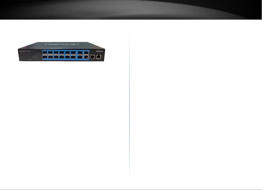
TL2-FG142 supports 14 fiber ports SFP type with 100/1000M bps and 2 RJ-45 Copper port with adaptive 10/100/1000M bps.
1.1 Introduction of the management functions
The Switch supports in-band management function from Http/Telnet/SNMP interfaces. Console is supported for local command-line settings. It supports network configuration functions, like VLAN, Trunking, Port Mirror, QoS, spanning tree and software backup/update. Users can configure these functions for different network applications. The following is a brief introduction about these functions before the detail operation sections.
1. VLAN (Virtual LAN)
VLAN can divide the switch to several broadcast domains to prevent network traffic between different user groups. This switch supports 802.1Q tag-based VLAN and Portbased VLAN. Users with the same VLAN ID can transfer data to each other. The network traffic will be blocked if they have different VLAN ID. VLAN Stacking function for 802.1Q tag-based VLAN is supported. It allows two VLAN tags in a packet for 802.1Q VLAN tunnelling application through a central network.
2. Trunk
If two switches are cascaded together, the bottleneck will happen at the cascading connection. If more cables could be used for the cascading connection, it will reduce the bottleneck problem. In normal case, switches will become unstable because of traffic looping when more than one cable is connected between them. If the switches support trunk function, they can treat these cables as one connection between them. The traffic looping will not happen between these cables and the switches will work stable with bigger bandwidth between them.
Notes: About redundant application
TL2-FG142
The trunk connection supports redundant function. If any trunk cable is broken, the traffic going through that cable will be transferred to another trunk cable automatically. For example, if traffic of user port 6 is assigned to Port 1 in a Trunk and Port 1 connection breaks, Port 2 will take over the traffic for Port 6 automatically. (It could be used for redundant application.)
3. Spanning Tree Protocol / Rapid Spanning Tree Protocol
Spanning tree is a protocol to prevent network loop in network topology. If network loop happens, it will cause switches in the network unstable because more and more traffic will loop in the network. If network loop happens, spanning tree protocol will block one connection in the loop automatically. But it will also cause a period of delay (30 seconds for STP and shorter time for RSTP) if any network connection is changed because of the network topology detection operation of the protocol.
Because there could be more than one switch in the network, users can configure this function for their network spanning tree application.
4. Port Mirror
This switch operates in store-and-forward algorithm so it is not possible to monitor network traffic from another connection port. But the port mirror function can copy packets from some monitored port to another port for network monitor.
5. QoS
For Quality of Service request in a network, packets could be classified to different forwarding priorities. For real-time network traffic (like video, audio), it needs higher priority than normal network traffic. With the definition of packet priority, it could have 8 priority levels (from 0 to 7). This switch supports eight priority level queues on each port. It could be configured for port-based, 802.1P tagged based, or DiffServ of IP packets priority. User can define the mapping of priority values to the priority queues.
6. Static Mac ID in ARL table
The switch can learn the Mac address from user’s packets and keep these Mac address in the ARL table for store-and-forward table lookup operation. But these Mac addresses will be deleted from ARL table after some time when users do not send any packets to the switch. This operation is called aging and the time is called aging time. It is about 5 minutes normally (it could be changed by users.) If users want to keep a Mac address always in ARL table on some port, they can assign the Mac address to ARL table. These Mac ID are called Static Mac address. This switch supports static Mac address assignment. The static Mac address assignment will also limit the Mac address could be
© Copyright 2019 TRENDnet. All Rights Reserved.
1

TRENDnet User’s Guide |
TL2-FG142 |
used on the assigned port only with the port security configuration function. For example, assigning “00-00-e2-11-22-33” to Port 5 will always keep this Mac ID alive on
Port 5 but also limit this Mac address could work on Port 5 only.
Note: About Static Mac Address Filter-in (port binding) function
There is a Mac Security function for port security. If Mac Table Learning is set to
“Secure”, only these static Mac addresses can access network through the assigned port. The other Mac addresses will be forbidden for network access through that port. This function can be used for port binding security application. Please refer to Section 6.3 for the details of the Mac address filter-in operation of the switch.
7. Dynamic Mac ID Number Limit
Beside Static Mac ID Limit, there is another Dynamic Mac ID Number Limit function for Mac address security on port. This function can limit the Mac ID number to access network through a port. For example, five Mac ID are allowed for Port 2. That means up to five users are allowed, but don’t care who the users are. It is done by “Limit Control” function in “Security - Network” function.
8. IEEE 802.1x Port Security Function
If the 802.1x function is enabled, the switch will act as an authenticator for users accessing network through the switch. It will need a RADIUS server for the authentication function. Users will be asked for username and password before network access. If the RADIUS server authenticates it, the switch will enable the port for network access. This function is very useful for network security application to prevent illegal users access network through the switch.
9. Rate Control
This function can limit the traffic rate for physical ports. The traffic could be ingress traffic or egress traffic. This function can limit the network bandwidth utilization of users.
10. IP Multicast with IGMP Snooping
IP multicast function can forward packets to a group of users connected on different ports. The user group is learned by the switch from packets of IGMP active router with IGMP snooping function. It is often used for video applications
11. MVR (Multicast VLAN Registration)
VLAN function will isolate traffic between VLAN groups. But it will also isolate IP multicast traffic for subscribers in different VLANs. The MVR function allows one
multicast VLAN to be shared by subscribers in different VLANs. That can reduce the multicast traffic for VLANs.
12. IP Source Guard
This function can limit the IP address for accessing network from switch port. That can prevent illegal IP problem in network.
13. ACL (Access Control List)
This function is used to define network access control policy - a list of packet filtering rules. The filtering conditions are Layer2 ~ Layer4 - including Mac address, VLAN ID, Ethernet Type, IP address, ARP Packets, ... If conditions are matched, the traffic could be discarded, forwarded, logging or rate limit.
14. LLDP (Link Layer Discover Protocol)
LLDP protocol is used by network devices to advertise their identity, capabilities, and interconnections on a LAN network. This switch can advertise its system information, and show the information of the connected network devices by LLDP protocol.
15. Software Backup/Update
This switch supports backup and update functions for its internal software and its network configuration. It could be done in two ways.
a.From web browser : doing by http protocol and by web browser for run-time code and configuration backup/update.
b.From telnet or console command : doing by tftp protocol for run-time code and configuration backup/update.
1.2 General Features
All 1G Ethernet ports are tri-speed 10/100/1000 Mbps ports for RJ-45 port
Fully non-blocking wire-speed switching performance for all frame sizes
Eight priorities and eight queues per port
Dual leaky bucket policing per queue and per port
DWRR scheduler/shaper per queue and per port with a mix of strict and weighted queues
© Copyright 2019 TRENDnet. All Rights Reserved.
2

TRENDnet User’s Guide
256 TCAM-based egress tagging entries
Up to 256 TCAM-based classification entries for Quality of Service (QoS) and VLAN membership
Up to 512 host identity entries for source IP guarding
Energy Efficient Ethernet (IEEE 802.3az) is supported by both the switch core and the internal copper PHYs
1.3 Layer-2 Switching
8,192 MAC addresses
4,096 VLANs (IEEE 802.1Q)
Push/pop/translate up to two VLAN tags; translation on ingress and/or on egress
Up to 256 QoS and VLAN TCAM entries
256 VLAN egress tagging TCAM entries
Link aggregation (IEEE 802.3ad)
Independent and shared VLAN learning
Provider Bridging (VLAN Q-in-Q) support (IEEE 802.1ad)
Rapid Spanning Tree Protocol support (IEEE 802.1w)
Multiple Spanning Tree Protocol support (IEEE 802.1s)
Jumbo frame support up to 9.6 kilobytes with programmable MTU per port
1.4 Multicast
8K IPv4/IPv6 multicast groups
Internet Group Management Protocol version 2 (IGMPv2) support
Internet Group Management Protocol version 3 (IGMPv3) support with source specific multicast forwarding
1.5 Carrier Ethernet
Provider Bridge (Q-in-Q) switch 8K MACs, 4K VLANs
Per port per queue Dual Leaky Bucket Service Policers with PCP or DSCP remarking per Service Point
Statistics and Tagging options per Service Point
TL2-FG142
OAM hardware for generating CCM messages, CCM checking is done by software
Software for OAM and protection switching
1.6 Quality of Service
Eight QoS queues per port with strict or deficit weighted round-robin scheduling (DWRR)
256 QoS and VLAN TCAM entries
DSCP translation, both ingress and/or egress
DSCP remarking based on QoS class and drop precedence level
VLAN (PCP, DEI, and VID) translation, both ingress and egress
PCP and DEI remarking based on QoS class and drop precedence level
Per-queue and per-port policing and shaping, programmable in steps of 100 kbps
Per-flow policing through TCAM-based pattern matching, up to 256 policers
Full-duplex flow control (IEEE 802.3X) and half-duplex backpressure, symmetric and asymmetric
1.7 Security
Generic storm controllers for flooded broadcast, flooded multicast, and flooded unicast traffic
Port-based and MAC-based access control (IEEE 802.1X)
Per-port ingress and egress mirroring
1.8 Standard References
This switch uses the following industry references.
Document |
Title |
Revision |
|
|
|
IEEE |
|
|
|
|
|
IEEE 802.1ad |
802.1Q Amendment 4: Provider Bridges |
-2005 |
|
|
|
IEEE |
802.1Q Amendment 5: Connectivity Fault Management |
Evolving |
P802.1ag |
(CFM) |
|
|
|
|
IEEE 802.1D |
Media Access Control (MAC) Bridges |
-2004 |
|
|
|
IEEE 802.1Q |
Virtual Bridged Local Area Networks |
-2005 |
|
|
|
IEEE 802.3 |
Local and metropolitan area networks — Specific |
-2008 |
|
requirements Carrier sense multiple access with collision |
|
|
detection (CSMA/CD) access method and physical layer |
|
|
specifications |
|
|
|
|
© Copyright 2019 TRENDnet. All Rights Reserved.
3

TRENDnet User’s Guide
IEEE 802.3az |
Standard for Information Technology – |
-2010 |
|
Telecommunications and Information Exchange Between |
|
|
Systems - Local and Metropolitan Area Networks - |
|
|
Specific Requirements Part 3: Carrier Sense Multiple |
|
|
Access with Collision Detection (CSMA/CD) Access |
|
|
Method and Physical Layer Specifications - Amendment: |
|
|
Media Access Control Parameters, Physical Layers and |
|
|
Management Parameters for Energy-Efficient Ethernet |
|
|
|
|
IEEE 1588 |
Precision Clock Synchronization Protocol for Networked |
-2008 |
|
Measurement and Control Systems |
|
|
|
|
MEF |
|
|
|
|
|
MEF-9 |
Abstract Test Suite for Ethernet Services at the UNI |
October 2004 |
|
|
|
MEF-10.1 |
Ethernet Services Attributes Phase 2 |
November |
|
|
2006 |
|
|
|
MEF-14 |
Abstract Test Suite for Traffic Management Phase 1 |
November |
|
|
2005 |
|
|
|
MEF-16 |
Ethernet Local Management Interface (E-LMI) |
January 2006 |
|
|
|
ITU-T |
|
|
|
|
|
Y.1731 |
OAM Functions and Mechanisms for Ethernet Based |
5/22/2006 |
|
Networks |
|
|
|
|
G.8261 |
Timing and Synchronization Aspects in Packet Networks |
12/14/2006 |
|
|
|
IETF |
|
|
|
|
|
RFC-2236 |
Internet Group Management Protocol, Version 2 |
November |
|
(IGMPv2) |
1997 |
|
|
|
RFC-2710 |
Multicast Listener Discovery for IPv6 (MLDv1) |
October 1999 |
|
|
|
RFC-2819 |
Remote Network Monitoring (RMON) MIB |
May 2000 |
|
|
|
RFC-2863 |
The Interfaces Group MIB |
June 2000 |
|
|
|
RFC-3376 |
Internet Group Management Protocol, Version 3 |
October 2002 |
|
(IGMPv3) |
|
|
|
|
|
|
TL2-FG142 |
|
|
|
|
|
RFC-3635 |
Definitions of Managed Objects for Ethernet-like |
|
September |
|
Interface Types |
|
2003 |
|
|
|
|
Other |
|
|
|
|
|
|
|
ENG-46158 |
Cisco Serial GMII (SGMII) Specification |
|
1.7 |
|
|
|
|
EDCS-540123 |
Cisco QSGMII Specification |
|
1.3 |
|
|
|
|
JESD79 |
DDR2 SDRAM Specification |
|
2B |
|
|
|
|
1.9 Front Panel LEDs Indicators
The LEDs provide useful information about the switch and the status of all individual ports.
|
LED |
|
Color |
|
State |
|
Indication |
|
|
|
|
|
|
|
|
|
|
|
|
|
ON |
-Power on |
|
|
Power |
|
Green |
|
|
|
|
|
|
|
OFF |
|
- Power off |
||
|
|
|
|
|
|
||
|
|
|
|
|
|
|
|
|
Run |
|
Green |
|
OFF |
|
- System failed |
|
|
|
|
|
|
||
|
|
|
Blinking |
|
-System is ready |
||
|
|
|
|
|
|
||
|
|
|
|
|
|
|
|
|
|
|
Green |
|
ON |
|
-Connection (or link) at 1000Mbps |
|
|
|
|
|
|
|
|
|
|
|
Amber |
|
ON |
|
-Connection (or link) at 100Mbps |
|
Fiber(Link) |
|
|
|
|
|
|
|
|
|
|
OFF |
|
-Disconnection |
|
|
|
|
|
|
|
||
|
|
|
|
|
|
|
|
|
|
|
|
|
Blinking |
|
-Sending & Receiving data |
|
|
|
|
|
|
|
|
1.10 Rear Panel Connectors
The rear panel is provided the power connecter.
© Copyright 2019 TRENDnet. All Rights Reserved.
4

TRENDnet User’s Guide
2. Hardware Installation
This chapter provides unpacking and installation information for the Switch
2.1 Unpacking
Open the shipping carton and carefully unpack its contents. Please consult the packing list located in the User Manual to make sure all items are present and undamaged. If any item is missing or damaged, please contact your local reseller for replacement.
One Gigabit Management Switch
One AC power cord (*for AC power model only)
One console cable
This user's manual
If any item is found missing or damaged, please contact the local reseller for replacement.
2.2 Switch Installation
For safe switch installation and operation, it is recommended that you:
Visually inspect the power cord to see that it is secured fully to the AC power connector.
Make sure that there is proper heat dissipation and adequate ventilation around the switch.
Do not place heavy objects on the switch
Desktop Installation
When installing the switch on a desktop, make sure that there is enough ventilation space between the device and the objects around it.
Rack Installation
The switch can be mounted in an EIA standard size 19-inch rack, which can be placed in a wiring closet with other equipment. To install, attach the mounting brackets to the switch’s side panels (one on each side) and secure them with the screws provided
(please note that these brackets are not designed for palm size switches).
Then, use the screws provided with the equipment rack to mount the switch in the rack.
Please be aware of following safety Instructions when installing:
1.Elevated Operating Ambient - If installed in a closed or multi-unit rack assembly, the operating ambient temperature of the rack environment may be greater than room ambient. Therefore, consideration should be given to installing the
TL2-FG142
equipment in an environment compatible with the maximum ambient temperature specified by the manufacturer.
2.Reduced Air Flow - Installation of the equipment in a rack should be such that the amount of air flow required for safe operation of the equipment is not compromised.
3.Mechanical Loading - Mounting of the equipment in the rack should be such that a hazardous condition is not achieved due to uneven mechanical loading.
4.Circuit Overloading - Consideration should be given to the connection of the equipment to the supply circuit, and the effect that overloading of the circuits might have on overcurrent protection and supply wiring. Appropriate consideration of equipment nameplate ratings should be used when addressing this concern.
2.3 Adding Module
This switch supports SFP (for 100/1000SX/LX/…modules) connectors for fiber optic connection. Because the SFP slots support hot-swap function, you can plug/unplug SFP transceiver to/from the SFP slot directly. The switch can auto-detect the fiber optic connection from SFP slot.
3. Console
The TC-224T Switch allows hyper terminal to perform configuration and monitoring by using the Command Line Interface (CLI) via console port or telnet.
3.1 Console Setup
Step 1: Connect computer to the device through the console port.
Step 2: Open the terminal emulator software (like Hyper-Terminal on Microsoft Windows machine, or “ Minicom” on Linux machine), then select the proper COM port for the connection. Set the terminal and port to the following parameters:
- Terminal Mode: VT-100
- Baud rate |
: 115200 bps |
- Data bits |
: 8 |
- Parity |
: None |
© Copyright 2019 TRENDnet. All Rights Reserved.
5
TRENDnet User’s Guide
- Stop bits |
: 1 |
- Flow Control |
: None |
Turning on the switch, then after few seconds of machine initialization, the system management terminal will display the login screen as show below.
3.2 Login
■Enter “ admin ” for the switch.
■Without the Password .
■You can see “ ”.
If you want to set IP address of switch, you can enter configuration mode to setup the IP address as the below.
TL2-FG142
# configure terminal
(config)# interface vlan 1
(config-if-vlan)# ip address 192.168.1.240 255.255.255.0
(config-if-vlan)#
4. Configuring with WEB
You are able to manage the switch with Http Web Browser. The default IP settingis192.168.0.1 and Net Mask 255.255.255.0. The default Gateway is 0.0.0.0. Before http connection, IP address configuration of the switch should be changed first.
1.Please follow the instruction in Section 3.1 to complete the console connection.
2.Login with “admin” (password is also none by default.)
3.Use “show” command to check IP address of the switch first.
4.Enter “show running-config interface vlan 1” command, and the prompt will show the IP address of the switch as the below.
© Copyright 2019 TRENDnet. All Rights Reserved.
6
TRENDnet User’s Guide |
TL2-FG142 |
#show running-config interface vlan 1 Building configuration...
interface vlan 1
ip address 192.168.0.1 255.255.255.0 end
#.
5.If IP address needs to be changed, please login to the configuration mode as the below setps...
#configure terminal
(config)# interface vlan 1
(config-if-vlan)# ip address 192.168.1.240 255.255.255.0
(config-if-vlan)#
After IP address configuration done and the switch is connected to network, you are able to start Http connection by entering IP address of the switch in the web browser as the below section.
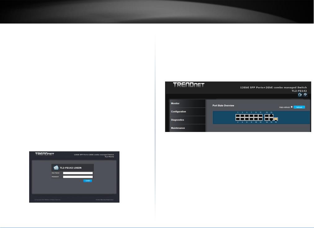
4.1 Login
When connected, the Switch has the following pre-configured switch IP addresses
“192.168.10.200 “as shown below.
To access the Web Utility,
Configure your PC to the same network segment as the switch. For example, you could set the PC to IP address 192.168.10.x with a subnet mask of 255.255.255.0.
Connect the PC to any of LAN port designated 1 to 24 on the Front Panel.
Open the Web browser.
Enter the IP address of the GSHDSL.in the address field of the browser as example: http://192.168.10.200 and then press <Enter> to connect.
There is a default User Name “admin” for the GSHDSL.
Without password.
Then the management home page will be showed as the below.
4.2 Web Menus
This section introduces how to use web browser to manage the switch. There are 3 areas of the web-based management screen.
Left part of the management screen is a function list. Users can select one of them for status monitoring or switch configuration.
There are four operation groups in the function list.
1.Configuration: provide configure switch.
2.Monitor: get the function status and statistics of the switch.
3.Diagnostics: provide some tools for testing the switch
4.Maintenance: provide the maintenance features, for example firmware upgrade, configuration backup/restore, system reset,...
Middle part of the management screen is the main operation area for each function.
There are to icons logout and help menu at the Right part of the management screen.
© Copyright 2019 TRENDnet. All Rights Reserved.
7

TRENDnet User’s Guide
 Logout icon, click to exit the switch.
 Help icon, click to get the on-line help menus
4.3 Configuration
The features and functions of the Switch can be configured for optimum use through the Web-based Management Utility.
4.3.1 System
The System Setting allows the user to configure the IP address and the basic system information of the Switch.
4.3.1.1 Information
The switch system information is provided here. In this menu, user can setup the system contact, system name and system location, as below figure.
Items |
Description |
|
|
System |
The textual identification of the contact person for this managed node, together with |
Contact |
information on how to contact this person. The allowed string length is 0 to 255, and |
|
the allowed content is the ASCII characters from 32 to 126. |
|
|
System |
An administratively assigned name for this managed node. By convention, this |
Name |
is the node's fully-qualified domain name. A domain name is a text string drawn |
|
from the alphabet (A-Z a-z), digits (0-9), minus sign (-). No space characters are |
|
permitted as part of a name. The first character must be an alpha character. |
|
TL2-FG142 |
|
|
|
And the first or last character must not be a minus sign. The allowed string |
|
length is 0 to 255. |
|
|
System |
The physical location of this node (e.g., telephone closet, 3rd floor). The |
Location |
allowed string length is 0 to 255, and the allowed content is the ASCII |
|
characters from 32 to 126. |
|
|
Button
 Click to save changes.
 Click to undo any changes made locally and revert to previously saved values.
4.3.1.2 IP
Configure IP basic settings, control IP interfaces and IP routes, as below figure. The maximum number of interfaces supported is 8 and the maximum number of routes is 32.
© Copyright 2019 TRENDnet. All Rights Reserved.
8

TRENDnet User’s Guide |
TL2-FG142 |
IP Configuration
Items |
Description |
||||||||||||
|
|
|
|
|
|
|
|
|
|
|
|
|
|
|
|
|
|
|
|
|
|
|
|
|
|
|
|
Mode |
Configure whether the IP stack should act as a |
Host |
or a |
Router. |
In |
Host |
mode, IP traffic |
||||||
|
between interfaces will not be routed. In |
Router |
mode traffic is routed between all |
||||||||||
|
interfaces. |
||||||||||||
|
|
||||||||||||
DNS |
This setting controls the DNS name resolution done by the switch. The |
||||||||||||
Server |
following modes are supported: |
||||||||||||
|
|
|
|
|
|||||||||
|
From any DHCP interfaces. |
The first DNS server offered from a DHCP lease to a |
|||||||||||
|
DHCP-enabled interface will be used. |
||||||||||||
|
|
|
|
||||||||||
|
No DNS server. |
No DNS server will be used. |
|||||||||||
|
|
|
|||||||||||
|
Configured. |
Explicitly provide the IP address of the DNS Server in dotted |
|||||||||||
|
decimal notation. |
||||||||||||
|
|
||||||||||||
|
From this DHCP interface. |
Specify from which DHCP-enabled interface a |
|||||||||||
|
provided DNS server should be preferred. |
||||||||||||
|
|
||||||||||||
DNS |
When DNS proxy is enabled, system will relay DNS requests to the currently |
||||||||||||
Proxy |
configured DNS server, and reply as a DNS resolver to the client devices on the |
||||||||||||
|
network. |
||||||||||||
|
|
|
|
|
|
|
|
|
|
|
|
|
|
IP Interface |
|||||||||||||
|
|
||||||||||||
Items |
Description |
||||||||||||
|
|
||||||||||||
Delete |
Select this option to delete an existing IP interface |
||||||||||||
|
|
||||||||||||
VLAN |
The VLAN associated with the IP interface. Only ports in this VLAN will be able |
||||||||||||
|
to access the IP interface. This field is only available for input when creating an |
||||||||||||
|
new interface. |
||||||||||||
|
|
||||||||||||
IPv4 |
Enable the DHCP client by checking this box. If this option is enabled, the |
||||||||||||
DHCP |
system will configure the IPv4 address and mask of the interface using the |
||||||||||||
Enabled |
DHCP protocol. The DHCP client will announce the configured System Name as |
||||||||||||
|
hostname to provide DNS lookup. |
||||||||||||
|
|
||||||||||||
IPv4 |
Enable the DHCP client by checking this box. If this option is enabled, the |
||||||||||||
DHCP |
system will configure the IPv4 address and mask of the interface using the |
||||||||||||
Fallback |
DHCP protocol. The DHCP client will announce the configured System Name as |
Timeout |
hostname to provide DNS lookup. |
|
|
IPv4 |
The number of seconds for trying to obtain a DHCP lease. After this period |
DHCP |
expires, a configured IPv4 address will be used as IPv4 interface address. A |
Fallback |
value of zero disables the fallback mechanism, such that DHCP will keep |
Timeout |
retrying until a valid lease is obtained. Legal values are 0 to 4294967295 |
|
seconds. |
|
|
IPv4 |
For DHCP interfaces with an active lease, this column show the current |
DHCP |
interface address, as provided by the DHCP server. |
Current |
|
Lease |
|
|
|
IPv4 |
The IPv4 address of the interface in dotted decimal notation. |
Address |
If DHCP is enabled, this field is not used. The field may also be left blank if IPv4 |
|
operation on the interface is not desired. |
|
|
IPv4 |
The IPv4 network mask, in number of bits (prefix length). Valid values are |
Mask |
between 0 and 30 bits for a IPv4 address. |
|
If DHCP is enabled, this field is not used. The field may also be left blank if IPv4 |
|
operation on the interface is not desired. |
|
|
IPv6 |
The IPv6 address of the interface. A IPv6 address is in 128-bit records |
Address |
represented as eight fields of up to four hexadecimal digits with a colon |
|
separating each field (:). For example, fe80::215:c5ff:fe03:4dc7. The symbol :: |
|
is a special syntax that can be used as a shorthand way of representing multiple |
|
16-bit groups of contiguous zeros; but it can appear only once. It can also |
|
represent a legally valid IPv4 address. For example, ::192.1.2.34. |
|
The field may be left blank if IPv6 operation on the interface is not desired. |
|
|
IPv6 |
The IPv6 network mask, in number of bits (prefix length). Valid values are |
Mask |
between 1 and 128 bits for a IPv6 address. |
|
The field may be left blank if IPv6 operation on the interface is not desired. |
|
|
Button |
|
|
Click to add a new IP interface. A maximum of 8 interfaces is supported. |
IP Routes |
|
© Copyright 2019 TRENDnet. All Rights Reserved.
9

TRENDnet User’s Guide
Items |
Description |
|
|
|
|
Delete |
Select this option to delete an existing IP route. |
|
|
|
|
Mask |
The destination IP network or host mask, in number of bits (prefix length). It |
|
Length |
defines how much of a network address that must match, in order to qualify |
|
|
for this route. Valid values are between 0 and 32 bits respectively 128 for IPv6 |
|
|
routes. Only a default route will have a mask length of 0 (as it will match |
|
|
anything). |
|
|
|
|
Gateway |
The IP address of the IP gateway. Valid format is dotted decimal notation or a |
|
|
valid IPv6 notation. Gateway and Network must be of the same type. |
|
|
|
|
Next |
The VLAN ID (VID) of the specific IPv6 interface associated with the gateway. |
|
Hop |
The given VID ranges from 1 to 4094 and will be effective only when the |
|
VLAN |
||
corresponding IPv6 interface is valid. |
||
(Only for |
||
If the IPv6 gateway address is link-local, it must specify the next hop VLAN for |
||
IPv6) |
the gateway. |
|
|
||
|
If the IPv6 gateway address is not link-local, system ignores the next hop VLAN |
|
|
for the gateway. |
|
|
|
|
Button |
|
|
|
Click to add a new IP route. A maximum of 32 routes is supported. |
 Click to save changes.
 Click to undo any changes made locally and revert to previously saved values.
4.3.1.3 NTP
NTP is an acronym for Network Time Protocol, a network protocol for synchronizing the clocks of computer systems. NTP uses UDP (datagrams) as transport layer. Configure NTP on this page.
TL2-FG142
Items Description
Mode Indicates the NTP mode operation. Possible modes are:
Enabled: Enable NTP client mode operation.
Disabled: Disable NTP client mode operation.
Server # Provide the IPv4 or IPv6 address of a NTP server. IPv6 address is in 128-bit records represented as eight fields of up to four hexadecimal digits with a colon separating each field (:). For example, 'fe80::215:c5ff:fe03:4dc7'. The symbol '::' is a special syntax that can be used as a shorthand way of representing multiple 16-bit groups of contiguous zeros; but it can appear only once. It can also represent a legally valid IPv4 address. For example, '::192.1.2.34'.
Button
 Click to save changes.
 Click to undo any changes made locally and revert to previously saved values.
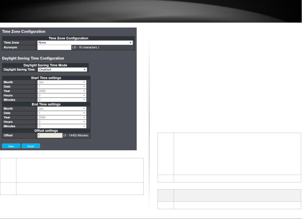
4.3.1.4 Time
This page allows you to configure the Time Zone.
© Copyright 2019 TRENDnet. All Rights Reserved.
10
TRENDnet User’s Guide |
TL2-FG142 |
Time Zone Configuration
Items |
Description |
|
|
Time |
Lists various Time Zones worldwide. Select appropriate Time Zone from the drop down |
Zone |
and click Save to set.. |
Acronym User can set the acronym of the time zone. This is a User configurable acronym to identify the time zone. ( Range : Up to 16 characters )
Daylight Saving Time Configuration
This page is used to setup Daylight Saving Time Configuration
Items |
Description |
|
|
|
|
Daylight |
This is used to set the clock forward or backward according to the configurations set |
|
Saving |
below for a defined Daylight Saving Time duration. Select 'Disable' to disable the |
|
Time |
Daylight Saving Time configuration. Select 'Recurring' and configure the Daylight Saving |
|
Time duration to repeat the configuration every year. Select 'Non-Recurring' and |
||
|
||
|
configure the Daylight Saving Time duration for single time configuration. ( Default : |
|
|
Disabled ) |
|
|
|
|
Start time settings |
||
Items |
Description |
|
|
Week |
Select the starting week number. |
|
|
Day |
Select the starting day. |
|
|
Month |
Select the starting month. |
|
|
Hours |
Select the starting hour. |
|
|
Minutes |
Select the starting minute. |
|
|
End time settings
Items |
Description |
|
|
Week |
Select the ending week number. |
|
|
Day |
Select the ending day. |
|
|
Month |
Select the ending month. |
|
|
Hours |
Select the ending hour. |
Minutes Select the ending minute.
Offset settings
Items Description
Offset Enter the number of minutes to add during Daylight Saving Time. ( Range: 1 to 1440 )
Button
© Copyright 2019 TRENDnet. All Rights Reserved.
11
TRENDnet User’s Guide |
TL2-FG142 |
 Click to save changes.
 Click to undo any changes made locally and revert to previously saved values.
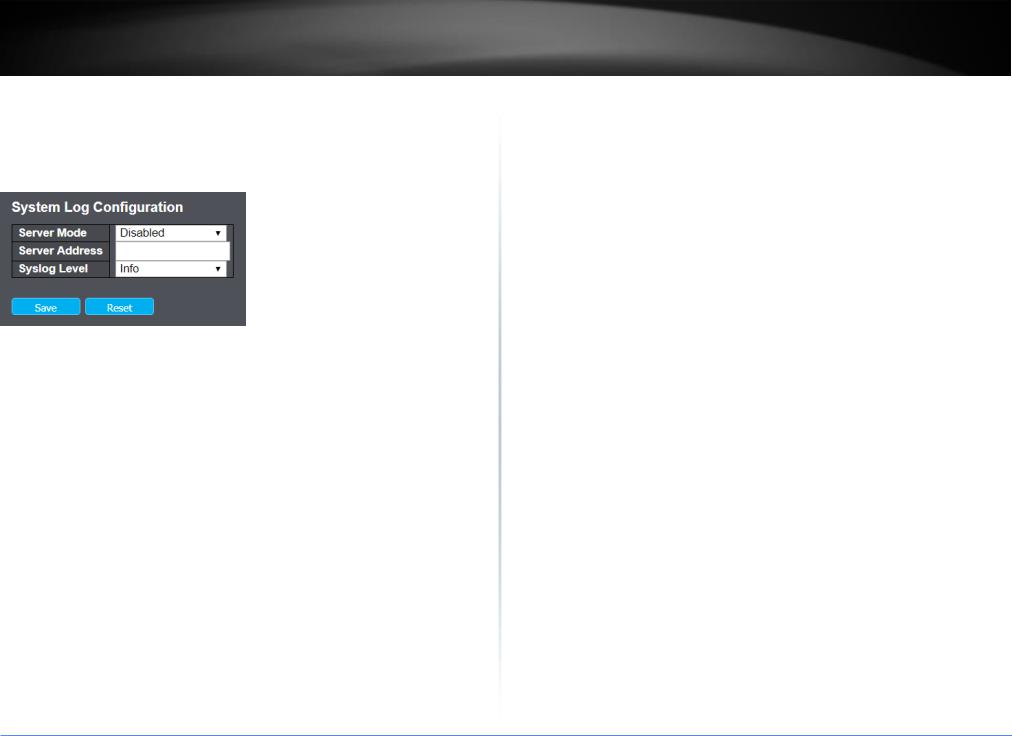
4.3.1.5 Log
Configure System Log on this page.
Items |
Description |
|
|
Server |
Indicates the server mode operation. When the mode operation is enabled, the syslog |
Mode |
message will send out to syslog server. The syslog protocol is based on UDP |
|
communication and received on UDP port 514 and the syslog server will not send |
|
acknowledgments back sender since UDP is a connectionless protocol and it does not |
|
provide acknowledgments. The syslog packet will always send out even if the syslog |
|
server does not exist. Possible modes are: |
|
Enabled: Enable server mode operation. |
|
Disabled: Disable server mode operation. |
|
|
Server |
Indicates the IPv4 host address of syslog server. If the switch provide DNS |
Address |
feature, it also can be a host name. |
|
|
Syslog |
Indicates what kind of message will send to syslog server. Possible modes are: |
Level |
Info: Send information, warnings and errors. |
|
|
|
Warning: Send warnings and errors. |
|
Error: Send errors. |
|
|
Button
 Click to save changes.
 Click to undo any changes made locally and revert to previously saved values.
4.3.2 Green Ethernet
Green Ethernet is a feature that reduces energy consumption on the switch. This way, the switch is more environmentally friendly, and your costs to run the switch are reduced. This section explains how to configure Green Ethernet on the Managed Switch.
4.3.2.1 Port Power Savings
Before introduce this feature, let us talk about EEE.
What is EEE?
EEE is a power saving option that reduces the power usage when there is low or no traffic utilization.
EEE works by powering down circuits when there is no traffic. When a port gets data to be transmitted all circuits are powered up. The time it takes to power up the circuits is named wakeup time. The default wakeup time is 17 us for 1Gbit links and 30 us for other link speeds. EEE devices must agree upon the value of the wakeup time in order to make sure that both the receiving and transmitting device has all circuits powered up when traffic is transmitted. The devices can exchange wakeup time information using the LLDP protocol.
EEE works for ports in auto-negotiation mode, where the port is negotiated to either 1G or 100 Mbit full duplex mode.
For ports that are not EEE-capable the corresponding EEE checkboxes are grayed out and thus impossible to enable EEE for.
When a port is powered down for saving power, outgoing traffic is stored in a buffer until the port is powered up again. Because there are some overhead in turning the port down and up, more power can be saved if the traffic can be buffered up until a large burst of traffic can be transmitted. Buffering traffic will give some latency in the traffic.
This page allows the user to configure the port power savings features.
© Copyright 2019 TRENDnet. All Rights Reserved.
12

TRENDnet User’s Guide
Port Power Savings Configuration
Items |
|
Description |
|
|
|
Optimize EEE for |
The switch can be set to optimize EEE for either best power saving or |
|
|
|
least traffic latency. |
|
|
|
Port Configuration |
||
|
|
|
Items |
|
Description |
|
|
|
Port |
The switch port number of the logical port. |
|
|
|
|
ActiPHY |
Link down power savings enabled. |
|
|
ActiPHY works by lowering the power for a port when there is no link. The port is |
|
|
power up for short moment in order to determine if cable is inserted. |
|
|
|
|
TL2-FG142
Perfect Reach |
Cable length power savings enabled. |
|
Perfect Reach works by determining the cable length and lowering the power for |
|
ports with short cables. |
|
|
EEE |
Controls whether EEE is enabled for this switch port. |
|
For maximizing power savings, the circuit isn't started at once transmit data is |
|
ready for a port, but is instead queued until a burst of data is ready to be |
|
transmitted. This will give some traffic latency. |
|
If desired it is possible to minimize the latency for specific frames, by mapping the |
|
frames to a specific queue (done with QOS), and then mark the queue as an urgent |
|
queue. When an urgent queue gets data to be transmitted, the circuits will be |
|
powered up at once and the latency will be reduced to the wakeup time. |
|
|
EEE Urgent |
Queues set will activate transmission of frames as soon as data is available. |
Queues |
Otherwise the queue will postpone transmission until a burst of frames can be |
|
transmitted. |
|
|
Button
 Click to save changes.
 Click to undo any changes made locally and revert to previously saved values.
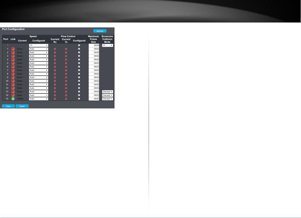
4.3.3 Port
This page displays current port configurations. Ports can also be configured here.
© Copyright 2019 TRENDnet. All Rights Reserved.
13
TRENDnet User’s Guide |
TL2-FG142 |
Port Configuration
Items |
|
Description |
||||||||||||
|
|
|
|
|
|
|
|
|
|
|
|
|
|
|
Port |
This is the logical port number for this row. |
|||||||||||||
|
|
|
|
|
|
|
|
|
|
|
|
|
|
|
Link |
The current link state is displayed graphically. Green indicates the link is |
|||||||||||||
|
up and red that it is down. |
|||||||||||||
|
|
|
|
|
|
|
|
|
|
|
|
|
|
|
Current |
Provides the current link speed of the port. |
|||||||||||||
|
|
|||||||||||||
Configured |
Selects any available link speed for the given switch port. Only speeds |
|||||||||||||
|
supported by the specific port is shown. Possible speeds are: |
|||||||||||||
|
|
|
|
|
|
|
|
|
|
|
|
|
|
|
|
Disabled |
- Disables the switch port operation. |
|
|
|
|
|
|
||||||
|
|
|
|
|
|
|
|
|
|
|
|
|||
|
Auto |
- Port auto negotiating speed with the link partner and selects the |
||||||||||||
|
highest speed that is compatible with the link partner. |
|||||||||||||
|
|
|
|
|
|
|
|
|
|
|
|
|||
|
10Mbps HDX |
- Forces the cu port in 10Mbps half duplex mode. |
|
|
|
|||||||||
|
|
|
|
|
|
|
|
|
|
|||||
|
10Mbps FDX |
- Forces the cu port in 10Mbps full duplex mode. |
|
|
|
|||||||||
|
|
|
|
|
|
|
|
|||||||
|
100Mbps HDX |
- Forces the cu port in 100Mbps half duplex mode. |
|
|||||||||||
|
|
|
|
|
|
|||||||||
|
100Mbps FDX |
- Forces the cu port in 100Mbps full duplex mode. |
|
|||||||||||
|
|
|
|
|||||||||||
|
1Gbps FDX |
- Forces the port in 1Gbps full duplex |
|
|||||||||||
|
|
|
|
|
|
|
|
|
|
|
|
|
|
|
|
2.5Gbps FDX |
- Forces the Serdes port in 2.5Gbps full duplex mode. |
||||
|
|
|
|
|
||
|
SFP_Auto_AMS |
- Automatically determines the speed of the SFP. Note: |
||||
|
There is no standardized way to do SFP auto detect, so here it is done by |
|||||
|
reading the SFP rom. Due to the missing standardized way of doing SFP |
|||||
|
auto detect some SFPs might not be detectable. The port is set in AMS |
|||||
|
mode. Cu port is set in Auto mode. |
|||||
|
|
|
|
|||
|
100-FX |
- SFP port in 100-FX speed. Cu port disabled. |
||||
|
|
|
|
|||
|
100-FX_AMS |
- Port in AMS mode. SFP port in 100-FX speed. Cu port in |
||||
|
Auto mode. |
|||||
|
|
|
||||
|
1000-X - SFP |
|
port in 1000-X speed. Cu port disabled. |
|||
|
|
|||||
|
1000-X_AMS |
- Port in AMS mode. SFP port in 1000-X speed. Cu port in |
||||
|
Auto mode. |
|||||
|
Ports in AMS mode with 1000-X speed has Cu port preferred. |
|||||
|
Ports in AMS mode with 1000-X speed has fiber port preferred. |
|||||
|
Ports in AMS mode with 100-FX speed has fiber port preferred. |
|||||
|
|
|||||
Flow Control |
When Auto Speed is selected on a port, this section indicates the flow |
|||||
Configured |
control capability that is advertised to the link partner. |
|||||
|
|
|
|
|
||
|
When a fixed-speed setting is selected, that is what is used. The Current |
|||||
|
Rx column indicates whether pause frames on the port are obeyed, and |
|||||
|
the Current Tx column indicates whether pause frames on the port are |
|||||
|
transmitted. The Rx and Tx settings are determined by the result of the |
|||||
|
last Auto-Negotiation. |
|||||
|
Check the configured column to use flow control. This setting is related to |
|||||
|
the setting for Configured Link Speed. |
|||||
|
|
|||||
Maximum |
Enter the maximum frame size allowed for the switch port, including FCS. |
|||||
Frame Size |
|
|
|
|
|
|
|
|
|||||
Excessive |
Configure port transmit collision behavior. |
|||||
Collision |
Discard: Discard frame after 16 collisions (default). |
|||||
Mode |
||||||
Restart: Restart back off algorithm after 16 collisions. |
||||||
|
||||||
|
|
|
|
|
|
|
Button |
|
|
|
|
|
|
© Copyright 2019 TRENDnet. All Rights Reserved.
14
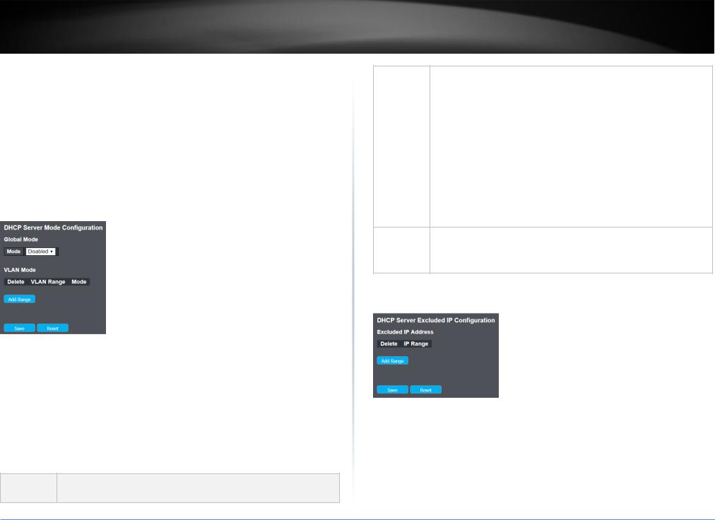
TRENDnet User’s Guide
 Click to save changes.
 Click to undo any changes made locally and revert to previously saved values.
  Click to refresh the page. Any changes made locally will be undone.
4.3.4 DHCP
DHCP Snooping is used to block intruder on the untrusted ports of the switch device when it tries to intervene by injecting a bogus DHCP reply packet to a legitimate conversation between the DHCP client and server.
4.3.4.1 Server-Mode
This page configures global mode and VLAN mode to enable/disable DHCP server per system and per VLAN.
Global Mode
Configure operation mode to enable/disable DHCP server per system.
Items |
Description |
|
|
Mode |
Configure the operation mode per system. Possible modes are: |
|
Enabled: Enable DHCP server per system. |
|
Disabled: Disable DHCP server pre system. |
|
|
VLAN Mode
Configure operation mode to enable/disable DHCP server per VLAN.
Items Description
TL2-FG142
VLAN Range Indicate the VLAN range in which DHCP server is enabled or disabled. The first VLAN ID must be smaller than or equal to the second VLAN ID. BUT, if the VLAN range contains only 1 VLAN ID, then you can just input it into either one of the first and second VLAN ID or both.
On the other hand, if you want to disable existed VLAN range, then you can follow the steps.
1.press Add VLAN Range to add a new VLAN range.
2.input the VLAN range that you want to disable.
3.choose Mode to be Disabled.
4.press Save to apply the change.
Then, you will see the disabled VLAN range is removed from the DHCP Server mode configuration page.
Mode |
Indicate the the operation mode per VLAN. Possible modes are: |
|
Enabled: Enable DHCP server per VLAN. |
|
Disabled: Disable DHCP server pre VLAN. |
4.3.4.2 Server-Excluded IP
This page configures excluded IP addresses. DHCP server will not allocate these excluded IP addresses to DHCP client.
Items |
Description |
|
|
IP Range |
Define the IP range to be excluded IP addresses. The first excluded IP |
|
must be smaller than or equal to the second excluded IP. BUT, if the IP |
|
range contains only 1 excluded IP, then you can just input it to either |
|
one of the first and second excluded IP or both. |
|
|
© Copyright 2019 TRENDnet. All Rights Reserved.
15
TRENDnet User’s Guide |
TL2-FG142 |
4.3.4.3 Server-pool
This page manages DHCP pools. According to the DHCP pool, DHCP server will allocate IP address and deliver configuration parameters to DHCP client.
Add or delete pools.
Adding a pool and giving a name is to create a new pool with "default" configuration. If you want to configure all settings including type, IP subnet mask and lease time, you can click the pool name to go into the configuration page.
Items |
Description |
|
|
Name |
Configure the pool name that accepts all printable characters, except |
|
white space. If you want to configure the detail settings, you can click |
|
the pool name to go into the configuration page. |
|
|
Type |
Display which type of the pool is. |
|
Network: the pool defines a pool of IP addresses to service more than |
|
one DHCP client. |
|
Host: the pool services for a specific DHCP client identified by client |
|
identifier or hardware address. |
|
If "-" is displayed, it means not defined. |
|
|
IP |
Display network number of the DHCP address pool. |
|
If "-" is displayed, it means not defined. |
|
|
Subnet Mask |
Display subnet mask of the DHCP address pool. |
|
If "-" is displayed, it means not defined |
|
|
Lease Time Display lease time of the pool.
4.3.4.4 Snooping
Configure DHCP Snooping on this page.
Items |
Description |
|
|
Snooping |
Indicates the DHCP snooping mode operation. Possible modes are: |
Mode |
Enabled: Enable DHCP snooping mode operation. When DHCP snooping |
|
|
|
mode operation is enabled, the DHCP request messages will be |
|
forwarded to trusted ports and only allow reply packets from trusted |
|
ports. |
|
Disabled: Disable DHCP snooping mode operation. |
|
|
Port Mode |
Indicates the DHCP snooping port mode. Possible port modes are: |
Configuration |
Trusted: Configures the port as trusted source of the DHCP messages. |
|
Untrusted: Configures the port as untrusted source of the DHCP |
|
messages. |
|
|
© Copyright 2019 TRENDnet. All Rights Reserved.
16
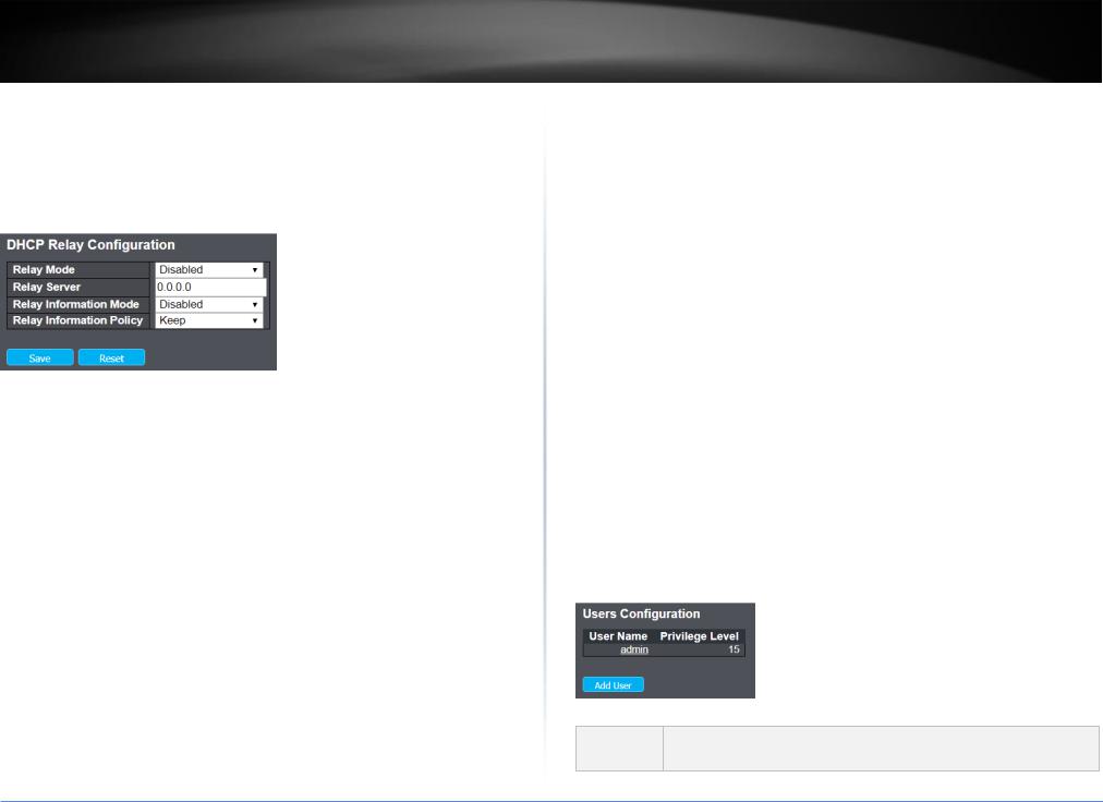
TRENDnet User’s Guide |
TL2-FG142 |
4.3.4.5 Relay
A DHCP relay agent is used to forward and to transfer DHCP messages between the clients and the server when they are not in the same subnet domain. It stores the incoming interface IP address in the GIADDR field of the DHCP packet. The DHCP server can use the value of GIADDR field to determine the assigned subnet. For such condition, please make sure the switch configuration of VLAN interface IP address and PVID(Port VLAN ID) correctly.
Items |
Description |
|
|
Relay Mode |
Indicates the DHCP relay mode operation. |
|
Possible modes are: |
|
Enabled: Enable DHCP relay mode operation. When DHCP relay mode |
|
operation is enabled, the agent forwards and transfers DHCP messages |
|
between the clients and the server when they are not in the same |
|
subnet domain. And the DHCP broadcast message won't be flooded for |
|
security considerations. |
|
Disabled: Disable DHCP relay mode operation. |
|
Relay Server |
|
|
Relay Server |
Indicates the DHCP relay server IP address. |
|
|
Relay |
Indicates the DHCP relay information mode option operation. The option |
Information |
82 circuit ID format as "[vlan_id][module_id][port_no]". The first four |
Mode |
characters represent the VLAN ID, the fifth and sixth characters are the |
|
module ID(in standalone device it always equal 0, in stackable device it |
|
means switch ID), and the last two characters are the port number. For |
|
example, "00030108" means the DHCP message receive form VLAN ID 3, |
|
switch ID 1, port No 8. And the option 82 remote ID value is equal the |
|
switch MAC address. |
|
|
|
Possible modes are: |
|
Enabled: Enable DHCP relay information mode operation. When DHCP |
|
relay information mode operation is enabled, the agent inserts specific |
|
information (option 82) into a DHCP message when forwarding to DHCP |
|
server and removes it from a DHCP message when transferring to DHCP |
|
client. It only works when DHCP relay operation mode is enabled. |
|
Disabled: Disable DHCP relay information mode operation. |
|
|
Relay |
Indicates the DHCP relay information option policy. When DHCP relay |
Information |
information mode operation is enabled, if the agent receives a DHCP |
Policy |
message that already contains relay agent information it will enforce the |
|
policy. The 'Replace' policy is invalid when relay information mode is |
|
disabled. Possible policies are: |
|
Replace: Replace the original relay information when a DHCP message |
|
that already contains it is received. |
|
Keep: Keep the original relay information when a DHCP message that |
|
already contains it is received. |
|
Drop: Drop the package when a DHCP message that already contains |
|
relay information is received. |
|
|
4.3.5 Security
There are several security features that have been embedded in switch software. There are switch, network and AAA.
4.3.5.1 User
This page provides an overview of the current users. Currently the only way to login as another user on the web server is to close and reopen the browser.
The displayed values for each user are:
Items Description
© Copyright 2019 TRENDnet. All Rights Reserved.
17

TRENDnet User’s Guide |
TL2-FG142 |
|
|
|
|
User Name |
The name identifying the user. This is also a link to Add/Edit User. |
|
|
|
|
Privilege |
The privilege level of the user. The allowed range is 1 to 15. If the privilege |
|
Level |
level value is 15, it can access all groups, i.e. that is granted the fully |
|
|
control of the device. But others value need to refer to each group |
|
|
privilege level. User's privilege should be same or greater than the group |
|
|
privilege level to have the access of that group. By default setting, most |
|
|
groups privilege level 5 has the read-only access and privilege level 10 has |
|
|
the read-write access. And the system maintenance (software upload, |
|
|
factory defaults and etc.) need user privilege level 15. Generally, the |
|
|
privilege level 15 can be used for an administrator account, privilege level |
|
|
10 for a standard user account and privilege level 5 for a guest account. |
|
|
|
|
Button |
|
|
|
Click to add a new user. |
|
4.3.5.2Privilege Levels
This page provides an overview of the privilege levels.
|
Items |
Description |
|
|
|
|
|
|
Group Name |
The name identifying the privilege group. In most cases, a privilege level |
|
|
|
group consists of a single module (e.g. LACP, RSTP or QoS), but a few of |
|
|
|
|
|
© Copyright 2019 TRENDnet. All Rights Reserved. |
|
|
|
|
|
18 |
|
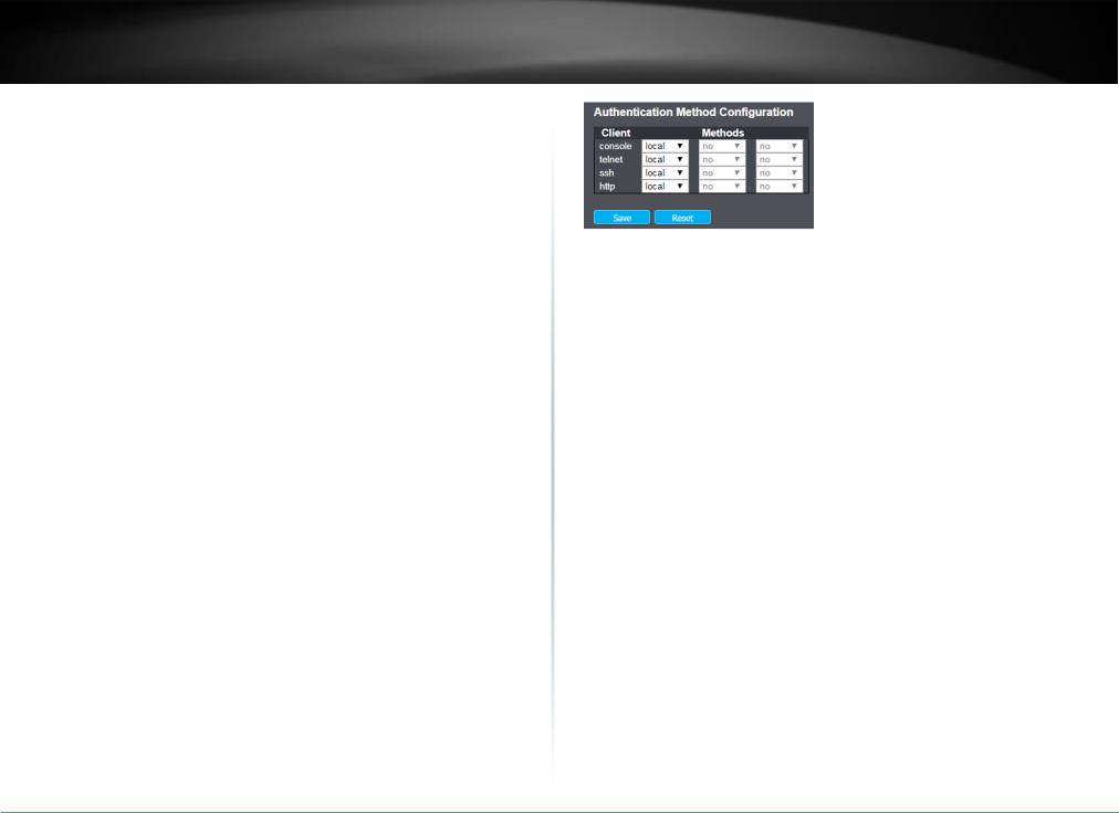
TRENDnet User’s Guide
|
them contains more than one. The following description defines these |
|
privilege level groups in details: |
|
System: Contact, Name, Location, Timezone, Daylight Saving Time, Log. |
|
Security: Authentication, System Access Management, Port (contains |
|
Dot1x port, MAC based and the MAC Address Limit), ACL, HTTPS, SSH, ARP |
|
Inspection, IP source guard. |
|
IP: Everything except 'ping'. |
|
Port: Everything except 'VeriPHY'. |
|
Diagnostics: 'ping' and 'VeriPHY'. |
|
Maintenance: CLISystem Reboot, System Restore Default, System |
|
Password, Configuration Save, Configuration Load and Firmware Load. |
|
WebUsers, Privilege Levels and everything in Maintenance. |
|
Debug: Only present in CLI. |
|
|
Privilege |
Every group has an authorization Privilege level for the following sub |
Levels |
groups: configuration read-only, configuration/execute read-write, |
|
status/statistics read-only, status/statistics read-write (e.g. for clearing of |
|
statistics). User Privilege should be same or greater than the authorization |
|
Privilege level to have the access to that group. |
|
|
Button
 Click to save changes.
 Click to undo any changes made locally and revert to previously saved values.
4.3.5.3Authentication Method Configuration
This page allows you to configure how a user is authenticated when he logs into the switch via one of the management client interfaces.
TL2-FG142
The table has one row for each client type and a number of columns, which are:
Items |
Description |
|
|
Client |
The management client for which the configuration below applies. |
|
|
Methods |
Method can be set to one of the following values: |
|
no: Authentication is disabled and login is not possible. |
|
local: Use the local user database on the switch for authentication. |
|
radius: Use remote RADIUS server(s) for authentication. |
|
tacacs+: Use remote TACACS+ server(s) for authentication. |
|
Methods that involves remote servers are timed out if the remote servers |
|
are offline. In this case the next method is tried. Each method is tried from |
|
left to right and continues until a method either approves or rejects a user. |
|
If a remote server is used for primary authentication it is recommended |
|
to configure secondary authentication as 'local'. This will enable the |
|
management client to login via the local user database if none of the |
|
configured authentication servers are alive. |
|
|
Button
 Click to save changes.
 Click to undo any changes made locally and revert to previously saved values.
4.3.5.4SSH Configuration
Configure SSH on this page.
© Copyright 2019 TRENDnet. All Rights Reserved.
19
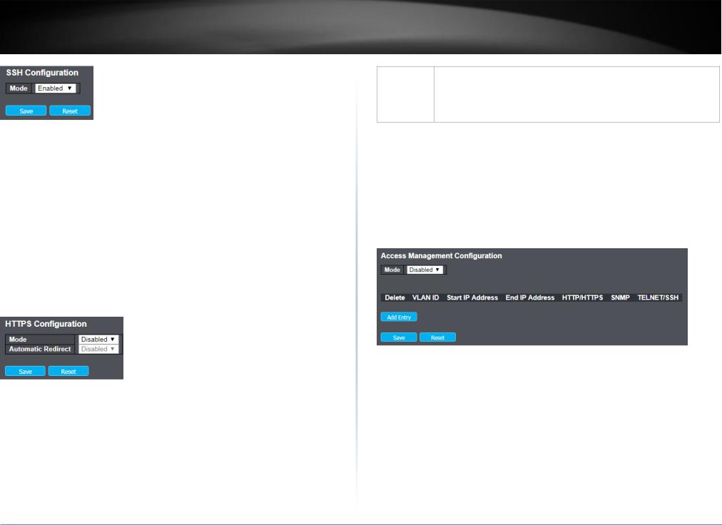
TRENDnet User’s Guide |
TL2-FG142 |
Items |
Description |
|
|
Mode |
Indicates the SSH mode operation. Possible modes are: |
|
Enabled: Enable SSH mode operation. |
|
Disabled: Disable SSH mode operation. |
|
|
Button
 Click to save changes.
 Click to undo any changes made locally and revert to previously saved values.
4.3.5.5HTTPS Configuration
Configure HTTPS on this page.
Items |
Description |
|
|
Mode |
Indicates the HTTPS mode operation. When the current connection is |
|
HTTPS, to apply HTTPS disabled mode operation will automatically |
|
redirect web browser to an HTTP connection. Possible modes are: |
|
Enabled: Enable HTTPS mode operation. |
|
Disabled: Disable HTTPS mode operation. |
|
|
Automatic |
Indicates the HTTPS redirect mode operation. It only significant if HTTPS |
Redirect |
mode "Enabled" is selected. Automatically redirects web browser to an |
|
|
HTTPS connection when both HTTPS mode and Automatic Redirect are enabled. Possible modes are:
Enabled: Enable HTTPS redirect mode operation.
Disabled: Disable HTTPS redirect mode operation.
Button
 Click to save changes.
 Click to undo any changes made locally and revert to previously saved values.
4.3.5.6Access Management Configuration
Configure access management table on this page. The maximum number of entries is 16. If the application's type match any one of the access management entries, it will allow access to the switch.
Items |
Description |
|
|
Mode |
Indicates the access management mode operation. Possible modes are: |
|
Enabled: Enable access management mode operation. |
|
Disabled: Disable access management mode operation. |
|
|
Delete |
Check to delete the entry. It will be deleted during the next save. |
|
|
VLAN ID |
Indicates the VLAN ID for the access management entry. |
|
|
Start IP |
Indicates the start IP address for the access management entry. |
address |
|
|
|
© Copyright 2019 TRENDnet. All Rights Reserved.
20
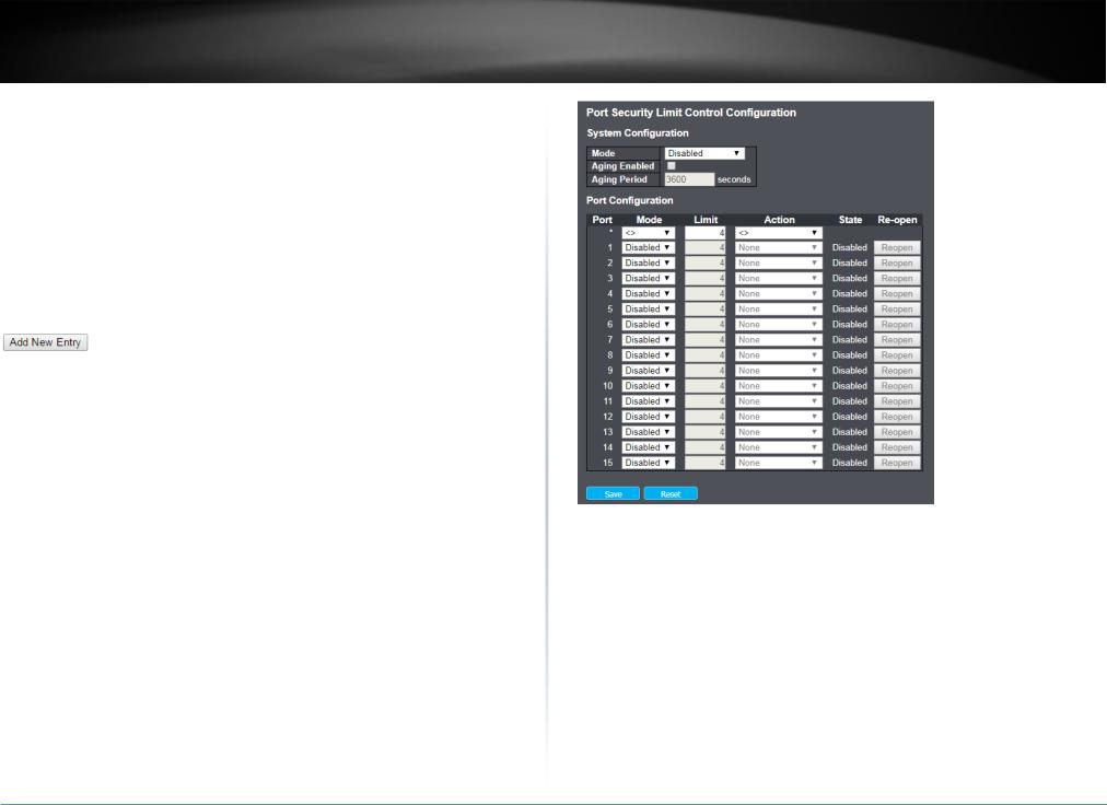
TRENDnet User’s Guide |
TL2-FG142 |
End IP |
Indicates the end IP address for the access management entry. |
address |
|
|
|
HTTP/HTTPS |
Indicates that the host can access the switch from HTTP/HTTPS interface |
|
if the host IP address matches the IP address range provided in the entry. |
|
|
SNMP |
Indicates that the host can access the switch from SNMP interface if the |
|
host IP address matches the IP address range provided in the entry. |
|
|
TELNET/SSH |
Indicates that the host can access the switch from TELNET/SSH interface |
|
if the host IP address matches the IP address range provided in the entry. |
|
|
Button |
|
|
Click to add a new access management entry. |
 Click to save changes.
 Click to undo any changes made locally and revert to previously saved values.
4.3.5.7Limit Control
This page allows you to configure the Port Security Limit Control system and port settings.
Limit Control allows for limiting the number of users on a given port. A user is identified by a MAC address and VLAN ID. If Limit Control is enabled on a port, the limit specifies the maximum number of users on the port. If this number is exceeded, an action is taken. The action can be one of the four different actions as described below.
The Limit Control module utilizes a lower-layer module, Port Security module, which manages MAC addresses learnt on the port.
The Limit Control configuration consists of two sections, a systemand a port-wide.
System Configuration
Items |
Description |
|
|
Mode |
Indicates if Limit Control is globally enabled or disabled on the switch. If |
|
globally disabled, other modules may still use the underlying |
|
functionality, but limit checks and corresponding actions are disabled. |
|
|
Aging |
If checked, secured MAC addresses are subject to aging as discussed |
Enabled |
under Aging Period . |
|
|
Aging Period |
If Aging Enabled is checked, then the aging period is controlled with this |
|
input. If other modules are using the underlying port security for |
|
securing MAC addresses, they may have other requirements to the aging |
|
period. The underlying port security will use the shorter requested aging |
|
period of all modules that use the functionality. |
|
|
© Copyright 2019 TRENDnet. All Rights Reserved.
21

TRENDnet User’s Guide |
TL2-FG142 |
The Aging Period can be set to a number between 10 and 10,000,000 seconds.
To understand why aging may be desired, consider the following scenario: Suppose an end-host is connected to a 3rd party switch or hub, which in turn is connected to a port on this switch on which Limit Control is enabled. The end-host will be allowed to forward if the limit is not exceeded. Now suppose that the end-host logs off or powers down. If it wasn't for aging, the end-host would still take up resources on this switch and will be allowed to forward. To overcome this situation, enable aging. With aging enabled, a timer is started once the end-host gets secured. When the timer expires, the switch starts looking for frames from the end-host, and if such frames are not seen within the next Aging Period, the end-host is assumed to be disconnected, and the correspon
Port Configuration
The table has one row for each port on the switch and a number of columns, which are:
Items |
Description |
|
|
Port |
The port number to which the configuration below applies. |
|
|
Mode |
Controls whether Limit Control is enabled on this port. Both this and the |
|
Global Mode must be set to Enabled for Limit Control to be in effect. |
|
Notice that other modules may still use the underlying port security |
|
features without enabling Limit Control on a given port. |
|
|
Limit |
The maximum number of MAC addresses that can be secured on this |
|
port. This number cannot exceed 1024. If the limit is exceeded, the |
|
corresponding action is taken. |
|
The switch is "born" with a total number of MAC addresses from which |
|
all ports draw whenever a new MAC address is seen on a Port Security- |
|
enabled port. Since all ports draw from the same pool, it may happen |
|
that a configured maximum cannot be granted, if the remaining ports |
|
have already used all available MAC addresses. |
|
|
Action |
If Limit is reached, the switch can take one of the following actions: |
|
None: Do not allow more than Limit MAC addresses on the port, but |
|
take no further action. |
|
|
Trap: If Limit + 1 MAC addresses is seen on the port, send an SNMP trap. If Aging is disabled, only one SNMP trap will be sent, but with Aging enabled, new SNMP traps will be sent every time the limit gets exceeded.
Shutdown: If Limit + 1 MAC addresses is seen on the port, shut down the port. This implies that all secured MAC addresses will be removed from the port, and no new address will be learned. Even if the link is physically disconnected and reconnected on the port (by disconnecting the cable), the port will remain shut down. There are three ways to re-open the port:
1)Boot the switch,
2)Disable and re-enable Limit Control on the port or the switch,
3)Click the Reopen button.
Trap & Shutdown: If Limit + 1 MAC addresses is seen on the port, both the "Trap" and the "Shutdown" actions described above will be taken.
State |
This column shows the current state of the port as seen from the Limit |
|
Control's point of view. The state takes one of four values: |
|
Disabled: Limit Control is either globally disabled or disabled on the port. |
|
Ready: The limit is not yet reached. This can be shown for all actions. |
|
Limit Reached: Indicates that the limit is reached on this port. This state |
|
can only be shown if Action is set to None or Trap. |
|
Shutdown: Indicates that the port is shut down by the Limit Control |
|
module. This state can only be shown if Action is set to Shutdown or |
|
Trap & Shutdown. |
|
|
Re-open |
If a port is shutdown by this module, you may reopen it by clicking this |
Button |
button, which will only be enabled if this is the case. For other methods, |
|
refer to Shutdown in the Action section. |
|
Note that clicking the reopen button causes the page to be refreshed, so |
|
non-committed changes will be lost. |
4.3.5.8NAS
This page allows you to configure the IEEE 802.1X and MAC-based authentication system and port settings.
© Copyright 2019 TRENDnet. All Rights Reserved.
22

TRENDnet User’s Guide
The IEEE 802.1X standard defines a port-based access control procedure that prevents unauthorized access to a network by requiring users to first submit credentials for authentication. One or more central servers, the backend servers, determine whether the user is allowed access to the network. These backend (RADIUS) servers are configured on the "Configuration→Security→AAA" page. The IEEE802.1X standard defines port-based operation, but non-standard variants overcome security limitations as shall be explored below.
MAC-based authentication allows for authentication of more than one user on the same port, and doesn't require the user to have special 802.1X supplicant software installed on his system. The switch uses the user's MAC address to authenticate against the backend server. Intruders can create counterfeit MAC addresses, which makes MACbased authentication less secure than 802.1X authentication.
The NAS configuration consists of two sections, a systemand a port-wide.
System Configuration
© Copyright 2019 TRENDnet. All Rights Reserved.
TL2-FG142
23

TRENDnet User’s Guide |
TL2-FG142 |
Items |
Description |
|
|
Mode |
Indicates if NAS is globally enabled or disabled on the switch. If |
|
globally disabled, all ports are allowed forwarding of frames. |
|
|
Reauthentication |
If checked, successfully authenticated supplicants/clients are |
Enabled |
reauthenticated after the interval specified by the Reauthentication |
|
Period. Reauthentication for 802.1X-enabled ports can be used to |
|
detect if a new device is plugged into a switch port or if a supplicant |
|
is no longer attached. |
|
For MAC-based ports, reauthentication is only useful if the RADIUS |
|
server configuration has changed. It does not involve communication |
|
between the switch and the client, and therefore doesn't imply that a |
|
client is still present on a port (see Aging Period below). |
|
|
Reauthentication |
Determines the period, in seconds, after which a connected client |
Period |
must be reauthenticated. This is only active if the Reauthentication |
|
Enabled checkbox is checked. Valid values are in the range 1 to 3600 |
|
seconds. |
|
|
EAPOL Timeout |
Determines the time for retransmission of Request Identity EAPOL |
|
frames. |
|
Valid values are in the range 1 to 65535 seconds. This has no effect |
|
for MAC-based ports. |
|
|
Aging Period |
This setting applies to the following modes, i.e. modes using the Port |
|
Security functionality to secure MAC addresses: |
|
If reauthentication is enabled and the port is in an 802.1X-based |
|
mode, this is not so critical, since supplicants that are no longer |
|
attached to the port will get removed upon the next |
|
reauthentication, which will fail. But if reauthentication is not |
|
enabled, the only way to free resources is by aging the entries. |
|
For ports in MAC-based Auth. mode, reauthentication doesn't cause |
|
direct communication between the switch and the client, so this will |
|
not detect whether the client is still attached or not, and the only |
|
way to free any resources is to age the entry. |
|
|
Hold Time |
This setting applies to the following modes, i.e. modes using the Port |
|
Security functionality to secure MAC addresses: |
|
|
•Single 802.1X
•Multi 802.1X
•MAC-Based Auth.
If a client is denied access - either because the RADIUS server denies the client access or because the RADIUS server request times out (according to the timeout specified on the
"Configuration→Security→AAA" page) - the client is put on hold in the Unauthorized state. The hold timer does not count during an ongoing authentication.
In MAC-based Auth. mode, the switch will ignore new frames coming from the client during the hold time.
The Hold Time can be set to a number between 10 and 1000000 seconds.
RADIUS-Assigned RADIUS-assigned QoS provides a means to centrally control the traffic QoS Enabled class to which traffic coming from a successfully authenticated
supplicant is assigned on the switch. The RADIUS server must be configured to transmit special RADIUS attributes to take advantage of this feature (see RADIUS-Assigned QoS Enabled below for a detailed description).
The "RADIUS-Assigned QoS Enabled" checkbox provides a quick way to globally enable/disable RADIUS-server assigned QoS Class functionality. When checked, the individual ports' ditto setting determine whether RADIUS-assigned QoS Class is enabled on that port. When unchecked, RADIUS-server assigned QoS Class is disabled on all ports
RADIUS-Assigned RADIUS-assigned VLAN provides a means to centrally control the VLAN Enabled VLAN on which a successfully authenticated supplicant is placed on
the switch. Incoming traffic will be classified to and switched on the RADIUS-assigned VLAN. The RADIUS server must be configured to transmit special RADIUS attributes to take advantage of this feature (see RADIUS-Assigned VLAN Enabled below for a detailed description).
The "RADIUS-Assigned VLAN Enabled" checkbox provides a quick way to globally enable/disable RADIUS-server assigned VLAN functionality. When checked, the individual ports' ditto setting determine whether RADIUS-assigned VLAN is enabled on that port.
© Copyright 2019 TRENDnet. All Rights Reserved.
24

TRENDnet User’s Guide
|
When unchecked, RADIUS-server assigned VLAN is disabled on all |
|
ports. |
|
|
Guest VLAN |
A Guest VLAN is a special VLAN - typically with limited network access |
Enabled |
- on which 802.1X-unaware clients are placed after a network |
|
administrator-defined timeout. The switch follows a set of rules for |
|
entering and leaving the Guest VLAN as listed below. |
|
The "Guest VLAN Enabled" checkbox provides a quick way to globally |
|
enable/disable Guest VLAN functionality. When checked, the |
|
individual ports' ditto setting determines whether the port can be |
|
moved into Guest VLAN. When unchecked, the ability to move to the |
|
Guest VLAN is disabled on all ports. |
|
|
Guest VLAN ID |
This is the value that a port's Port VLAN ID is set to if a port is moved |
|
into the Guest VLAN. It is only changeable if the Guest VLAN option is |
|
globally enabled. |
|
Valid values are in the range [1; 4095]. |
|
|
Max. Reauth. |
The number of times the switch transmits an EAPOL Request Identity |
Count |
frame without response before considering entering the Guest VLAN |
|
is adjusted with this setting. The value can only be changed if the |
|
Guest VLAN option is globally enabled. |
|
Valid values are in the range [1; 255]. |
|
|
Allow Guest |
The switch remembers if an EAPOL frame has been received on the |
VLAN if EAPOL |
port for the life-time of the port. Once the switch considers whether |
Seen |
to enter the Guest VLAN, it will first check if this option is enabled or |
|
disabled. If disabled (unchecked; default), the switch will only enter |
|
the Guest VLAN if an EAPOL frame has not been received on the port |
|
for the life-time of the port. If enabled (checked), the switch will |
|
consider entering the Guest VLAN even if an EAPOL frame has been |
|
received on the port for the life-time of the port. |
|
The value can only be changed if the Guest VLAN option is globally |
|
enabled. |
|
|
4.3.6 SNMP 4.3.6.1System
Configure SNMP on this page.
TL2-FG142
Items |
Description |
|
|
Mode |
Indicates the SNMP mode operation. Possible modes are: |
|
Enabled: Enable SNMP mode operation. |
|
Disabled: Disable SNMP mode operation. |
|
|
Version |
Indicates the SNMP supported version. Possible versions are: |
|
SNMP v1: Set SNMP supported version 1. |
|
SNMP v2c: Set SNMP supported version 2c. |
|
SNMP v3: Set SNMP supported version 3. |
|
|
Read |
Indicates the community read access string to permit access to SNMP |
Community |
agent. The allowed string length is 0 to 255, and the allowed content is |
|
the ASCII characters from 33 to 126. |
|
The field is applicable only when SNMP version is SNMPv1 or SNMPv2c. If |
|
SNMP version is SNMPv3, the community string will be associated with |
|
SNMPv3 communities table. It provides more flexibility to configure |
|
security name than a SNMPv1 or SNMPv2c community string. In addition |
|
to community string, a particular range of source addresses can be used |
|
to restrict source subnet. |
|
|
Write |
Indicates the community write access string to permit access to SNMP |
Community |
agent. The allowed string length is 0 to 255, and the allowed content is |
|
the ASCII characters from 33 to 126. |
|
The field is applicable only when SNMP version is SNMPv1 or SNMPv2c. If |
|
SNMP version is SNMPv3, the community string will be associated with |
|
SNMPv3 communities table. It provides more flexibility to configure |
|
security name than a SNMPv1 or SNMPv2c community string. In addition |
© Copyright 2019 TRENDnet. All Rights Reserved.
25
 Loading...