


TEG-284WS
TRENDnet User’s Guide
Cover Page

© Copyright 2017 TRENDnet. All Rights Reserved.
TRENDnet User’s Guide
Table of Contents
i
Contents
Product Overview ............................................................................ 1
Package Contents ........................................................................................................ 1
Features ...................................................................................................................... 1
Product Hardware Features ........................................................................................ 2
Switch Installation ........................................................................... 4
Desktop Hardware Installation .................................................................................... 4
Rack Mount Hardware Installation .............................................................................. 4
Basic Installation ......................................................................................................... 5
Connect additional devices to your switch .................................................................. 6
Configure your switch ...................................................................... 7
Access your switch management page ........................................................................ 7
System Info ................................................................................................................. 7
View your switch status information ................................................................. 7
System ........................................................................................................................ 9
Set your system information ............................................................................. 9
Set your IPv4 settings ...................................................................................... 10
Set your IPv6 settings ...................................................................................... 11
Add IPv6 neighbors .......................................................................................... 12
Set your DNS server settings ............................................................................ 13
Restrict access to switch management page .................................................... 13
Change administrator password and add accounts .......................................... 14
Change web idle login timeout settings ........................................................... 15
Set the switch date and time ........................................................................... 15
Enable HTTPS/SSL (Secure Socket Layer) management access ......................... 16
Enable DHCP Auto Configuration ..................................................................... 17
View and setup your switch logging ................................................................. 18
Enable or Disable SNMP .................................................................................. 19
Set the SNMP Engine ID ................................................................................... 19
Configure the SNMP View Table ...................................................................... 20
Configure the SNMP Group Access Table ......................................................... 21
Configure the SNMP User/Group Table ........................................................... 22
Configure the SNMP Community Table ........................................................... 23
Configure the SNMP Trap Management .......................................................... 24
Enable or Disable RMON ................................................................................. 25
Configure parameters for RMON Ethernet statistics........................................ 26
Configure parameters for RMON history control settings ................................ 27
Configure parameters for RMON alarms ......................................................... 28
Configure parameters for RMON events ......................................................... 29
View Statistics ................................................................................................. 30
View Traffic Information Statistics ................................................................... 30
View Error Information Statistics ..................................................................... 31
Enable IEEE 802.3az Power Saving Mode ........................................................ 32
Network.................................................................................................................... 32
Configure Physical Interfaces .......................................................................... 32
Configure Spanning Tree (STP, RSTP, MSTP) .................................................... 34
Configure Spanning Tree Protocol port settings .............................................. 35
Configure Spanning Tree Protocol MST settings (MSTP) .................................. 37
View your Spanning Tree Protocol Instance Information (MSTP) ..................... 38
Configure Spanning Tree Protocol MST Port Settings (MSTP) .......................... 38
Configure port trunk settings (Trunk/Link Aggregation) .................................. 39
View your trunk group status information ....................................................... 40
Configure your port priority ............................................................................ 40
Configure port mirror settings ......................................................................... 41
Enable loopback detection .............................................................................. 42
Add static unicast entries to the switch ........................................................... 43
Add static multicast entries to the switch ........................................................ 44
Configure IGMP Snooping Settings .................................................................. 45
Configure IGMP Snooping Router Ports ........................................................... 46
Configure Storm Control ................................................................................. 47
Set Ingress Rate Limiting ................................................................................. 47
Set Egress Rate Limiting .................................................................................. 48
Add, modify, and remove VLANs ..................................................................... 48
Configure VLAN Port Settings .......................................................................... 50
Configure the VLAN forwarding Table ............................................................. 50
View the switch VLAN dynamic forwarding table ............................................ 51
Create a private VLAN ..................................................................................... 51
View the current VLAN database ..................................................................... 52
Enable GVRP (GARP VLAN Registration Protocol) ............................................ 53
Set GVRP port settings .................................................................................... 53

© Copyright 2017 TRENDnet. All Rights Reserved.
TRENDnet User’s Guide
Table of Contents
ii
Set GVRP time settings .................................................................................... 54
Configuring Voice VLANs ................................................................................. 56
Create a Voice VLAN ........................................................................................ 57
Configure Voice VLAN OUI settings .................................................................. 58
Enable and configure LLDP .............................................................................. 59
View LLDP Neighbor Information ..................................................................... 61
QoS (Quality of Service) ............................................................................................ 61
Set CoS priority settings ................................................................................... 61
Set Port Priority ............................................................................................... 62
Set DSCP (Differentiated Services Code Point) Class Mapping settings............. 63
Set the Scheduling Algorithm .......................................................................... 63
Configure the IPv6 Traffic Class Settings .......................................................... 64
Security ..................................................................................................................... 65
Configure Port Access Control ......................................................................... 65
Create Dial-In Users (Local Authentication Method) ........................................ 66
Add RADIUS Servers (RADIUS Authentication Method) .................................... 67
Add TACACS+ Servers (TACACS+ Authentication Method) ............................... 68
Destination MAC Filter .................................................................................... 69
Denial of Service (DoS) .................................................................................... 70
Enable DHCP Snooping .................................................................................... 71
Assign DHCP Snooping to VLAN interfaces ....................................................... 72
Set Trusted DHCP Server Interfaces ................................................................. 73
Configure DHCP Address Binding Database ..................................................... 73
Configure Access Control Lists (ACL) ................................................................ 75
Configure Policy Settings ................................................................................. 75
View Access Profile List.................................................................................... 76
Find your ACL rules .......................................................................................... 77
Switch Maintenance ...................................................................... 78
Upgrade your switch firmware .................................................................................. 78
Firmware Upgrade via HTTP Settings ............................................................... 78
Firmware Upgrade via TFTP Settings................................................................ 78
Backup and restore your switch configuration settings ............................................. 79
Backup/Restore via HTTP Settings ................................................................... 79
Backup/Restore via TFTP Settings .................................................................... 80
Cable Diagnostics Test .............................................................................................. 81
Reboot/Reset to factory defaults .............................................................................. 82
Network Connectivity Test (Ping Tool) ...................................................................... 83
Using the Web Smart Switch Management Utility .......................... 84
System Requirements ............................................................................................... 84
Installation ................................................................................................................ 84
Using the Utility ........................................................................................................ 85
Launching the Utility ....................................................................................... 85
Discovery List .................................................................................................. 86
Monitor List .................................................................................................... 86
Device Setting ................................................................................................. 87
Main Menu Options ........................................................................................ 88
Switch Management Page Structure .............................................. 89
Technical Specifications ................................................................. 90
Troubleshooting ............................................................................. 92
Appendix ....................................................................................... 93

© Copyright 2017 TRENDnet. All Rights Reserved.
TRENDnet User’s Guide
TEG-284WS
1
Product Overview
TEG-284WS
Package Contents
In addition to your switch, the package includes:
Quick Installation Guide
CD-ROM (Utility & User’s Guide)
Power cord (1.8 m / 6 ft.)
Rack mount kit
If any package contents are missing or damaged, please contact the retail store, online
retailer, or reseller/distributor from which the product was purchased.
Features
TRENDnet’s 28-Port Gigabit Web Smart Switch, model TEG-284WS, is a cost-effective
switch solution for high-speed gigabit applications. Advanced traffic management,
access management controls, trouble shooting, and monitoring protocol support makes
this a powerful backbone solution for SMB networks. The web-based management
interface offers features for traffic control, troubleshooting, access controls, and
monitoring.
Hardware Design
Fanless rack mountable 1U metal housing features 24 gigabit ports and 4 shared gigabit
ports (RJ-45/SFP).
IPv6 Ready
This switch supports IPv6 configuration and IPv6 neighbor discovery.
Traffic Management
A broad range of network configurations are supported by: 802.3ad link aggregation,
Asymmetric VLAN, 802.1Q VLAN, Voice VLAN, RSTP, MSTP, Loopback Detection, GVRP,
802.1p Class of Service (CoS), port bandwidth management, and QoS queue scheduling
Troubleshooting
Traffic statistics and a convenient cable diagnostic test aid in network troubleshooting
Access Control
Features such as ACL, SSL, MAC/port filtering, 802.1X, TACACS+, and RADIUS are
compatible with layered access controls
Monitoring
RMON, SNMP, SNMP Trap, and Port Mirroring support administrator monitoring
solutions
© Copyright 2017 TRENDnet. All Rights Reserved.
TRENDnet User’s Guide
TEG-284WS
2
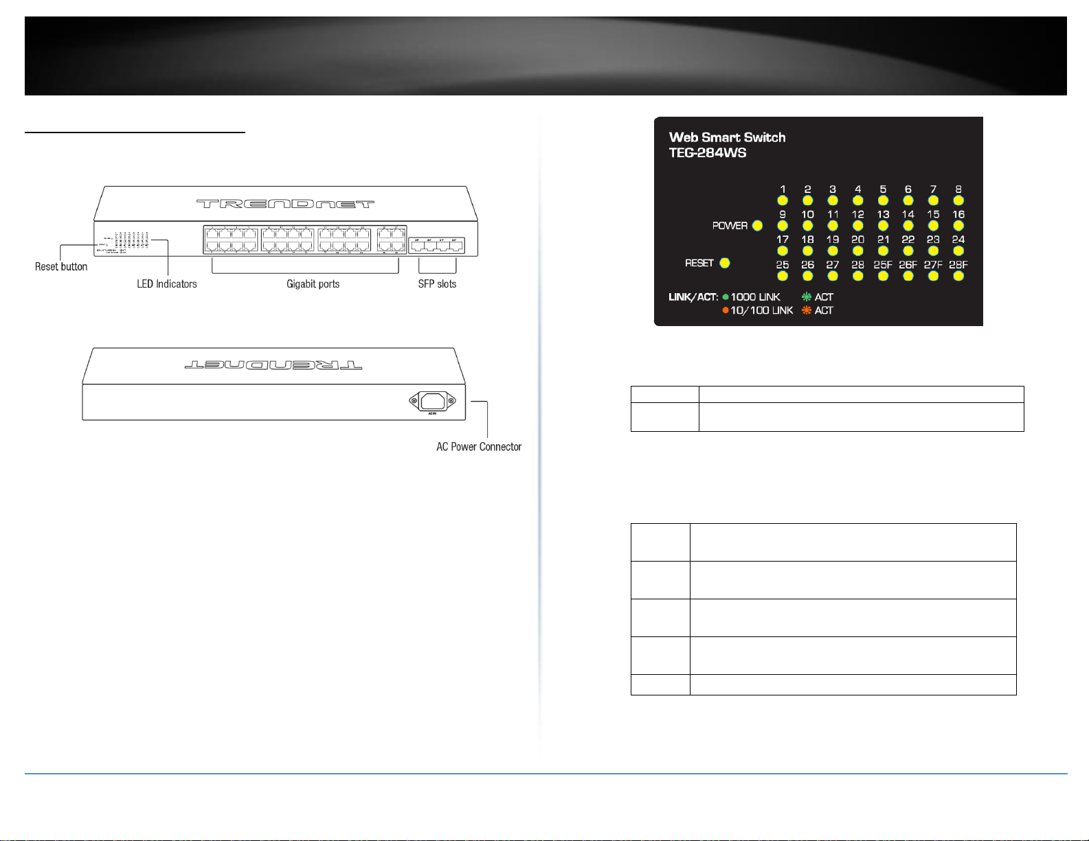
Product Hardware Features
Front View
Rear View
Reset Button – Press and hold the button 1~5 seconds and release to
reboot the device. Pressing the button more than 6 seconds will reset
the switch to factory defaults. The ports LEDs will turn off to indicate
that the reset was initiated.
Gigabit Ethernet Ports (1-28) – Connect network devices. Ports 25-28
are shared with SFP slots 25F-28F and are disabled when SFP slots (25F-
28F) are in use.
SFP Slots (25F-27F) – Supports optional 1000BASE-SX/LX mini-GBIC
modules for uplink or downlink connections.
Diagnostic LEDs
Power LED
On
:
When the Power LED is on, the device is receiving power.
Off
:
When the Power turns off, the power cord is not
connected or the device is not receiving power.
Gigabit Ethernet Port LEDs (1-28)
Link/Activity
Green
on
:
When the Green LED is on, the respective port is
connected to a 1Gbps Ethernet network.
Amber
on
:
When the Green LED lights on, the respective port is
connected to a 10/100Mbps Ethernet network.
Green
Blinking
:
When the LED is blinking green, the port is transmitting or
receiving data on the network at 1Gbps speed.
Amber
Blinking
:
When the LED is blinking amber, the port is transmitting
or receiving data on the network at 10/100Mbps speed.
Off
When the LED is off, the respective port is disconnected.

© Copyright 2017 TRENDnet. All Rights Reserved.
TRENDnet User’s Guide
TEG-284WS
3
SFP Slots (25F-28F)
Link/Activity
Green on
:
When the SFP LED is on, the link established using
the SFP module is operating at 1Gbps speed.
Green blinking
:
When the SFP LED is blinking, the port is
transmitting or receiving data on through the
1Gbps link established.
Amber on
When the SFP LED is on, the link established using
the SFP module is operating at 100Mbps speed.
Amber blinking
When the SFP LED is blinking, the port is
transmitting or receiving data on through the
100Mbps link established.
Off
No link established.
© Copyright 2017 TRENDnet. All Rights Reserved.
TRENDnet User’s Guide
TEG-284WS
4
Switch Installation
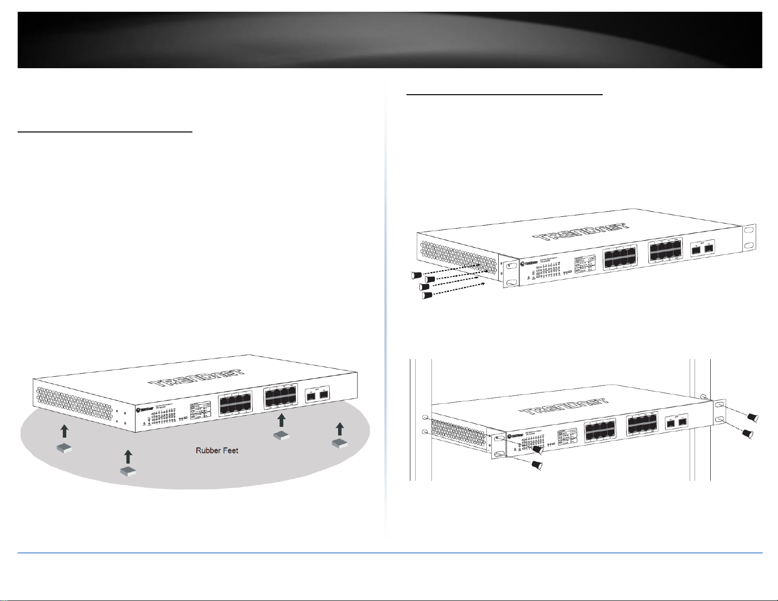
Desktop Hardware Installation
The site where you install the hub stack may greatly affect its performance. When
installing, consider the following pointers:
Note: The switch model may be different than the one shown in the example
illustrations.
Install the Switch in a fairly cool and dry place.
Install the Switch in a site free from strong electromagnetic field generators (such
as motors), vibration, dust, and direct exposure to sunlight.
Leave at least 10cm of space at the front and rear of the hub for ventilation.
Install the Switch on a sturdy, level surface that can support its weight, or in an
EIA standard-size equipment rack. For information on rack installation, see the
next section, Rack Mounting.
When installing the Switch on a level surface, attach the rubber feet to the
bottom of each device. The rubber feet cushion the hub and protect the hub
case from scratching.
Rack Mount Hardware Installation
The switch can be mounted in an EIA standard-size, 19-inch rack, which can be placed in
a wiring closet with other equipment. Attach the mounting brackets at the switch’s
front panel (one on each side), and secure them with the provided screws.
Note: The switch model may be different than the one shown in the example
illustrations.
Then, use screws provided with the equipment rack to mount each switch in the rack.
© Copyright 2017 TRENDnet. All Rights Reserved.
TRENDnet User’s Guide
TEG-284WS
5
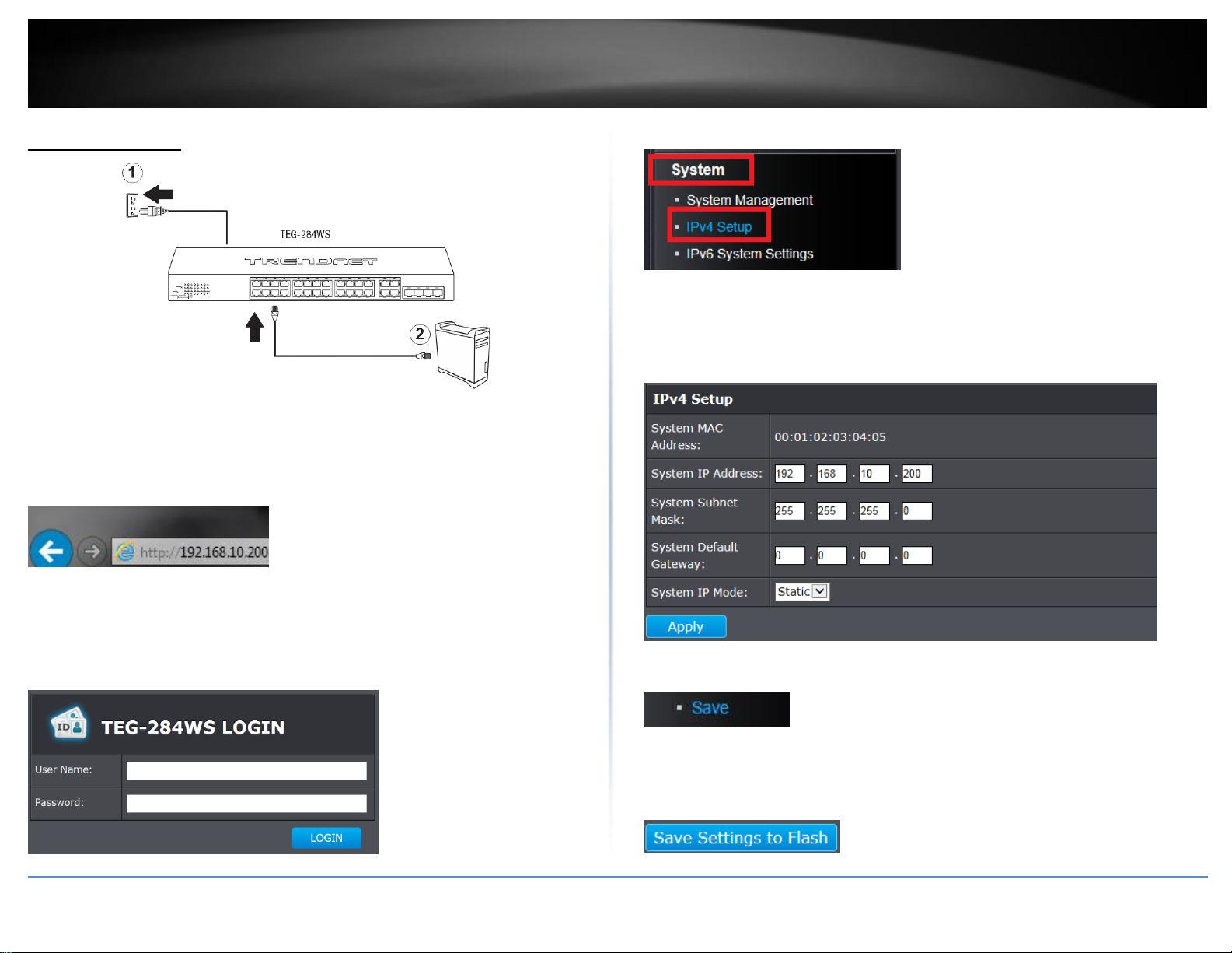
Basic Installation
3. Assign a static IP address to your computer’s network adapter in the subnet of
192.168.10.x (e.g. 192.168.10.25) and a subnet mask of 255.255.255.0.
4. Open your web browser, and type the IP address of the switch in the address bar, and
then press Enter. The default IP address is 192.168.10.200.
5. Enter the User Name and Password, and then click Login. By default:
User Name: admin
Password: admin
Note: User name and password are case sensitive.
6. Click System and then click IPv4 Setup.
7. Configure the switch IP address settings to be within your network subnet, then click
Apply.
Note: You may need to modify the static IP address settings of your computer’s network
adapter to IP address settings within your subnet in order to regain access to the switch.
5. In the left hand panel, click Tools, click on Configuration, and click Save.
6. Click Save Settings to Flash, then click OK.
Note: This step saves all configuration changes to the NV-RAM to ensure that if the
switch is rebooted or power cycled, the configuration changes will still be applied.
© Copyright 2017 TRENDnet. All Rights Reserved.
6
TRENDnet User’s Guide
TEG-284WS
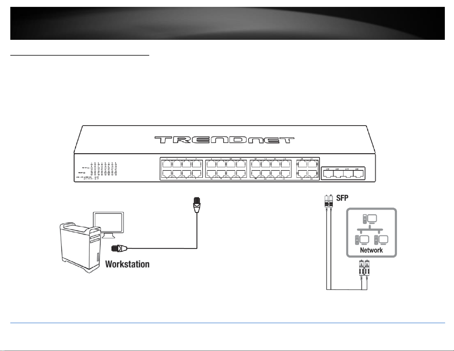
Connect additional devices to your switch
You can connect computers or other network devices to your switch using Ethernet cables to connect them to one of the available Gigabit Ethernet Ports (1-28). Check the status of the
LED indicators on the front panel of your switch to ensure the physical cable connection from your computer or device. You can use either the Gigabit Ethernet ports or SFP connections
as network uplinks. (SFP modules sold separately)
Note: If you encounter issues connecting to your network, there may be a problem with your computer or device network settings. Please ensure that your computer or device network
settings (also called TCP/IP settings) are configured properly within the network subnet your switch is connected.
© Copyright 2017 TRENDnet. All Rights Reserved.
TRENDnet User’s Guide
TEG-284WS
7
Configure your switch
Access your switch management page
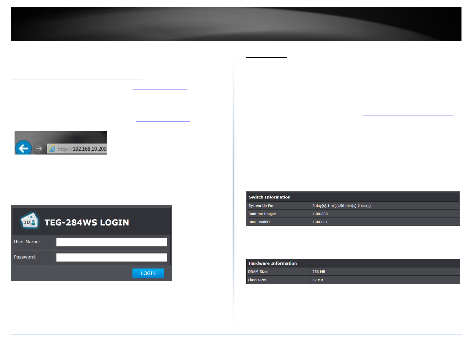
Note: Your switch default management IP address http://192.168.10.200 is accessed
through the use of your Internet web browser (e.g. Internet Explorer®, Firefox®,
Chrome™, Safari®, Opera™) and will be referenced frequently in this User’s Guide.
1. Open your web browser and go to the IP address http://192.168.10.200. Your switch
will prompt you for a user name and password.
2. Enter the user name and password. By default:
User Name: admin
Password: admin
Note: User Name and Password are case sensitive.
System Info
View your switch status information
System Info
You may want to check the general system information of your switch such as firmware
version, boot loader information and system uptime. Other information includes H/W
version, RAM/Flash size, administration information, IPv4 and IPv6 information.
1. Log into your switch management page (see “Access your switch management page”
on page 7).
2. Click on System Info.
System Information
System Up For – The duration your switch has been running continuously without
a restart/power cycle (hard or soft reboot) or reset.
Runtime Image: The current software or firmware version your switch is running.
Boot Loader – The current boot loader version your switch is running.
Hardware Information
DRAM Size: Displays your switch RAM memory size.
Flash Size: Displays your switch Flash memory size.
© Copyright 2017 TRENDnet. All Rights Reserved.
TRENDnet User’s Guide
TEG-284WS
8
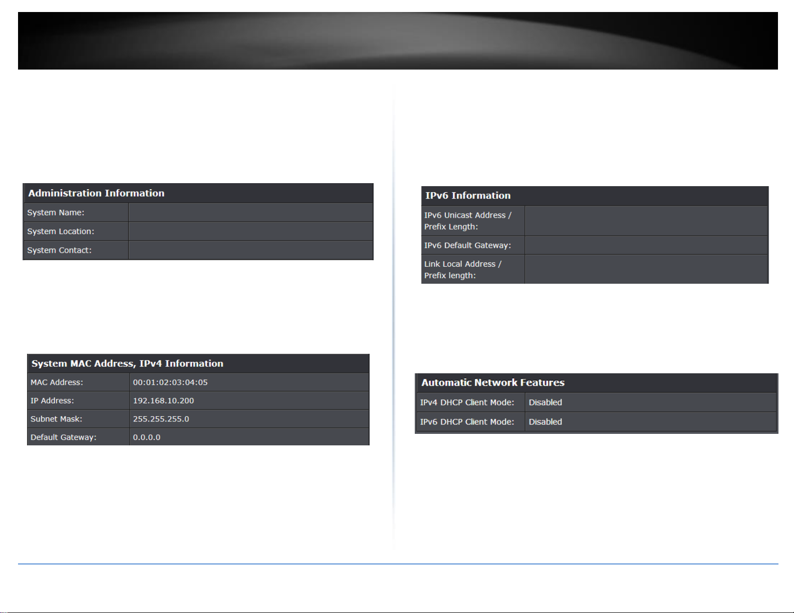
Administration Information
System Name – Displays the identifying system name of your switch. This
information can be modified under the System section.
System Location - Displays the identifying system location of your switch. This
information can be modified under the System section.
System Contact – Displays the identifying system contact or system administrator
of your switch. This information can be modified under the System section.
System MAC Address, IPv4 Information
MAC Address: Displays the switch system MAC address.
IP Address – Displays the current IPv4 address assigned to your switch.
Subnet Mask – Displays the current IPv4 subnet mask assigned to your switch.
Default Gateway – Displays the current gateway address assigned to your switch.
IPv6 Information
IPv6 Unicast Address / Prefix Length: Displays the current IPv6 address and
prefix assigned to your switch.
IPv6 Default Gateway: Displays the current IPv6 default gateway address
assigned to your switch.
Link Local Address / Prefix Length: Displays the current Link Local address and
prefix length assigned to your switch
Automatic Network Features
IPv4 DHCP Client Mode: Displays if your switch IPv4 address setting is set to
DHCP client.
IPv6 DHCP Client Mode: Displays if your switch IPv6 address setting is set to
DHCP client.
© Copyright 2017 TRENDnet. All Rights Reserved.
TRENDnet User’s Guide
TEG-284WS
9
System
Set your system information
System > System Management
This section explains how to assign a name, location, and contact information for the
switch. This information helps in identifying each specific switch among other switches
in the same local area network. Entering this information is optional.
1. Log into your switch management page (see “Access your switch management page”
on page 7).
2. Click on System, and click on System Management.
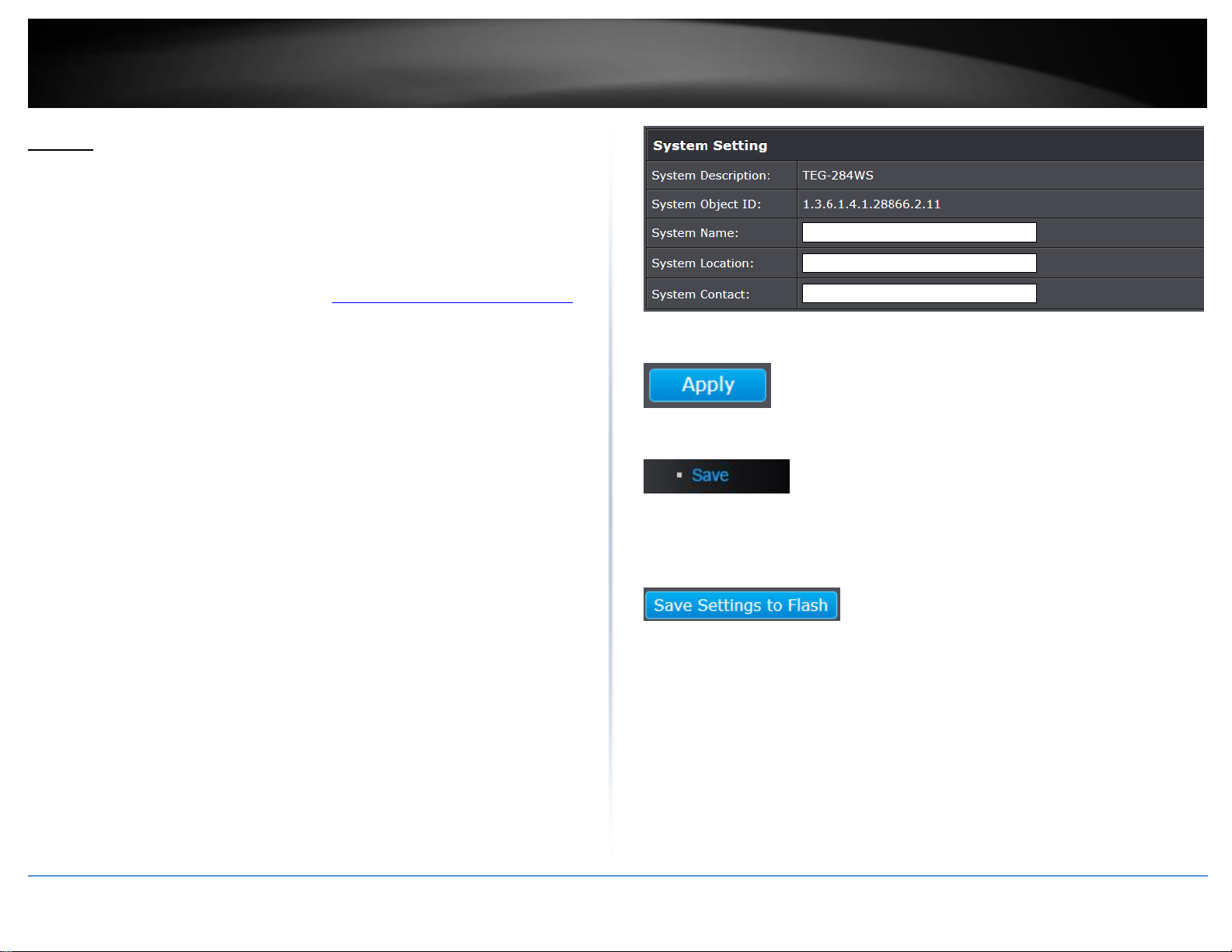
3. Review the settings. When you have completed making changes, click Apply to save
the settings.
System Description - Specifies the Switch model. You cannot change this
parameter.
System Object ID - Indicates the unique SNMP MIB object identifier that
identifies the switch model. You cannot change this parameter.
System Name - Specifies a name for the switch, the name is optional and may
contain up to 15 characters.
System Location - Specifies the location of the switch. The location is optional
and may contain up to 30 characters.
System Contact - Specifies the name of the network administrator responsible
for managing the switch. This contact name is optional and may contain up to
30 characters.
4. Click Apply.
5. In the left hand panel, click Tools, click on Configuration, and click Save.
6. Click Save Settings to Flash, then click OK.
Note: This step saves all configuration changes to the NV-RAM to ensure that if the
switch is rebooted or power cycled, the configuration changes will still be applied.
© Copyright 2017 TRENDnet. All Rights Reserved.
TRENDnet User’s Guide
TEG-284WS
10
Set your IPv4 settings
System > IPv4 Setup
This section allows you to change your switch IPv4 address settings. Typically, the IP
address settings should be changed to match your existing network subnet in order to
access the switch management page on your network.
Default Switch IPv4 Address: 192.168.10.200
Default Switch IPv4 Subnet Mask: 255.255.255.0
1. Log into your switch management page (see “Access your switch management page”
on page 7).
2. Click on System, and click on IPv4 Setup.
3. Review the settings. When you have completed making changes, click Apply to save
the settings.
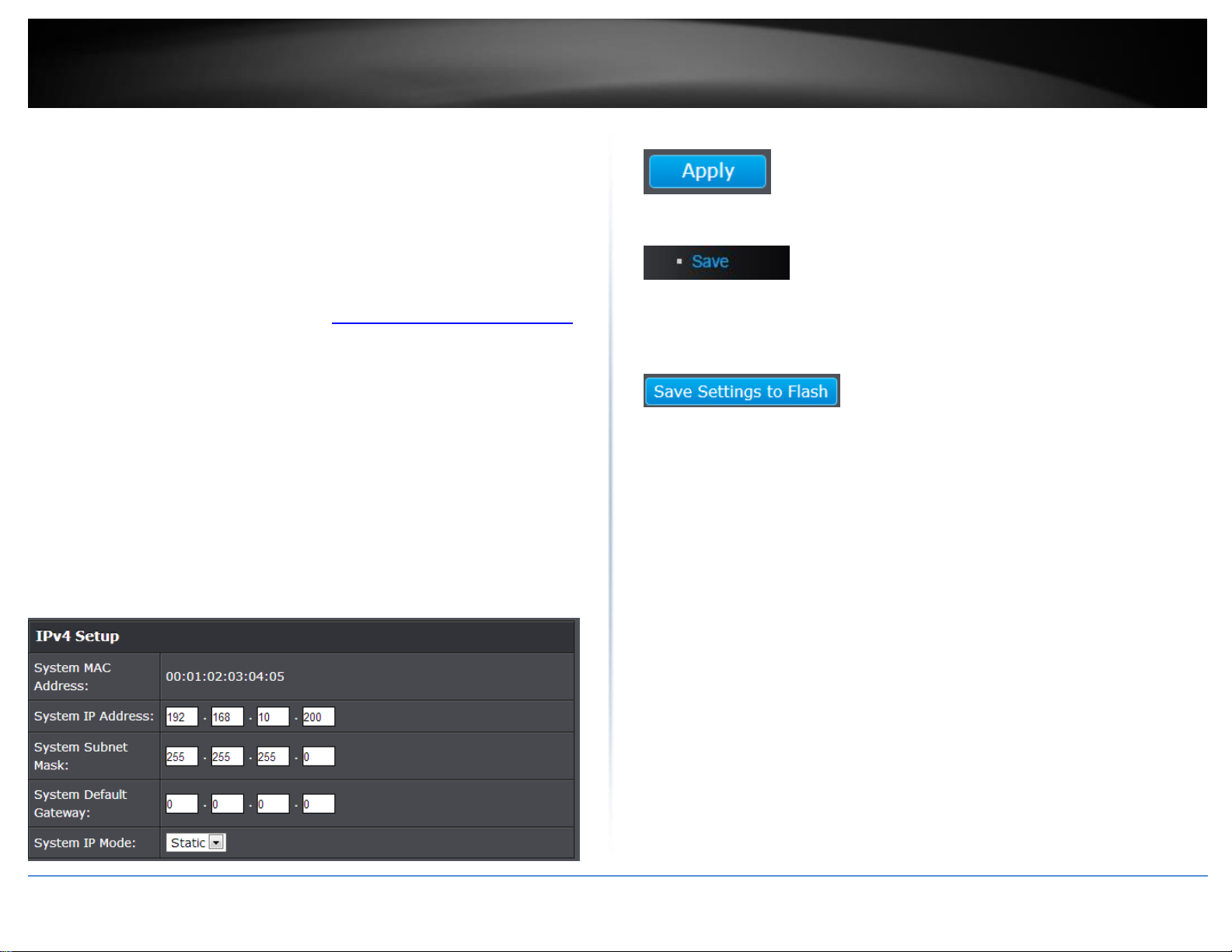
System MAC Address: Displays the switch MAC address information.
System IP Address: Enter the new switch IP address. (e.g. 192.168.200.200)
System Subnet Mask: Enter the new switch subnet mask. (e.g. 255.255.255.0)
System Default Gateway: Enter the default gateway IP address. (e.g.
192.168.200.1 or typically your router/gateway to the Internet).
System IP Mode: Click the drop-down list and select Static to manually specify
your IP address settings or DHCP to allow your switch to obtain IP address
settings automatically from a DHCP server on your network.
4. Click Apply.
5. In the left hand panel, click Tools, click on Configuration, and click Save.
6. Click Save Settings to Flash, then click OK.
Note: This step saves all configuration changes to the NV-RAM to ensure that if the
switch is rebooted or power cycled, the configuration changes will still be applied.
© Copyright 2017 TRENDnet. All Rights Reserved.
TRENDnet User’s Guide
TEG-284WS
11
Set your IPv6 settings
System > IPv6 System Settings
Internet Protocol version 6 (IPv6) is a new IP protocol designed to replace IP version 4
(IPv4). The IPv6 address protocol meets the current requirements of new applications
and the never ending growth of the Internet. The IPv6 address space makes more
addresses available but it must be approached with careful planning. Successful
deployment of IPv6 can be achieved with existing IPv4 infrastructures. With proper
planning and design, the transition between IP version 4 and 6 is possible today as well.
Use the IPv6 System Settings page to configure the IPv6 network interface, which is the
logical interface used for in-band connectivity with the switch via all of the switch's
front-panel ports. The configuration parameters associated with the switch's network
interface do not affect the configuration of the front-panel ports through which traffic is
switched or routed.
1. Log into your switch management page (see “Access your switch management page”
on page 7).
2. Click on System, and click on IPv6 System Settings.
3. Review the settings. When you have completed making changes, click Apply to save
the settings.
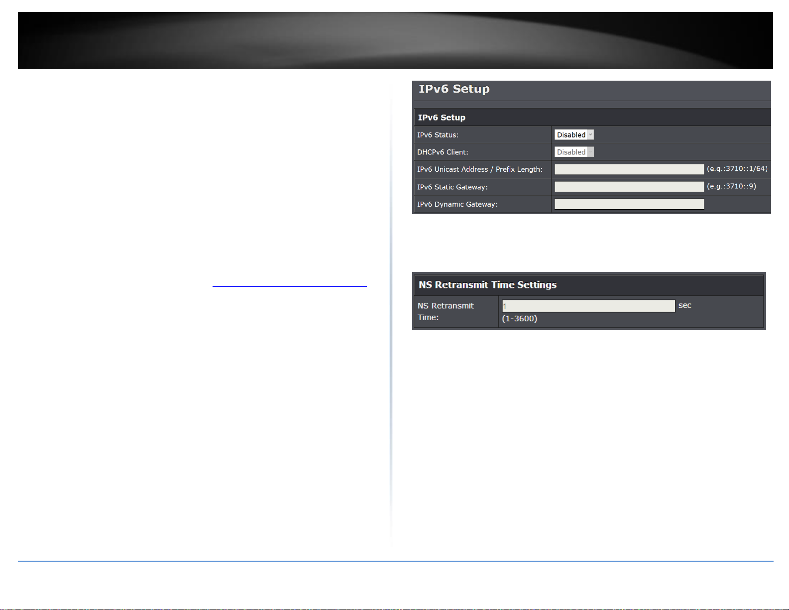
IPv6 Status: The IPv6 address for the IPv6 network interface is set in auto
configuration mode if this option is enabled. The default value is Disable. Auto
configuration can be enabled only when DHCPv6 is not enabled on any of the
management interfaces.
DHCPv6 Client: This option only displays when DHCPv6 is enabled.
IPv6 Unicast Address / Prefix Length: The IPv6 Unicast Address is an identifier
for a single interface, on a single node. A packet that is sent to a unicast
address is delivered to the interface identified by that address. Add the IPv6
prefix and prefix length to the IPv6 System Settings interface.
IPv6 Static Gateway: Specifies the corresponding Gateway of the IP address
entered into the field.
IPv6 Dynamic Gateway: To configure the switch to automatically obtain its IP
configuration from a DHCP server on your network.
NS Retransmit Time Settings: A constant that defines a nonzero number of
seconds between periodic reauthentication of the client. The field is 1~3600
seconds. The default setting is 1 second.
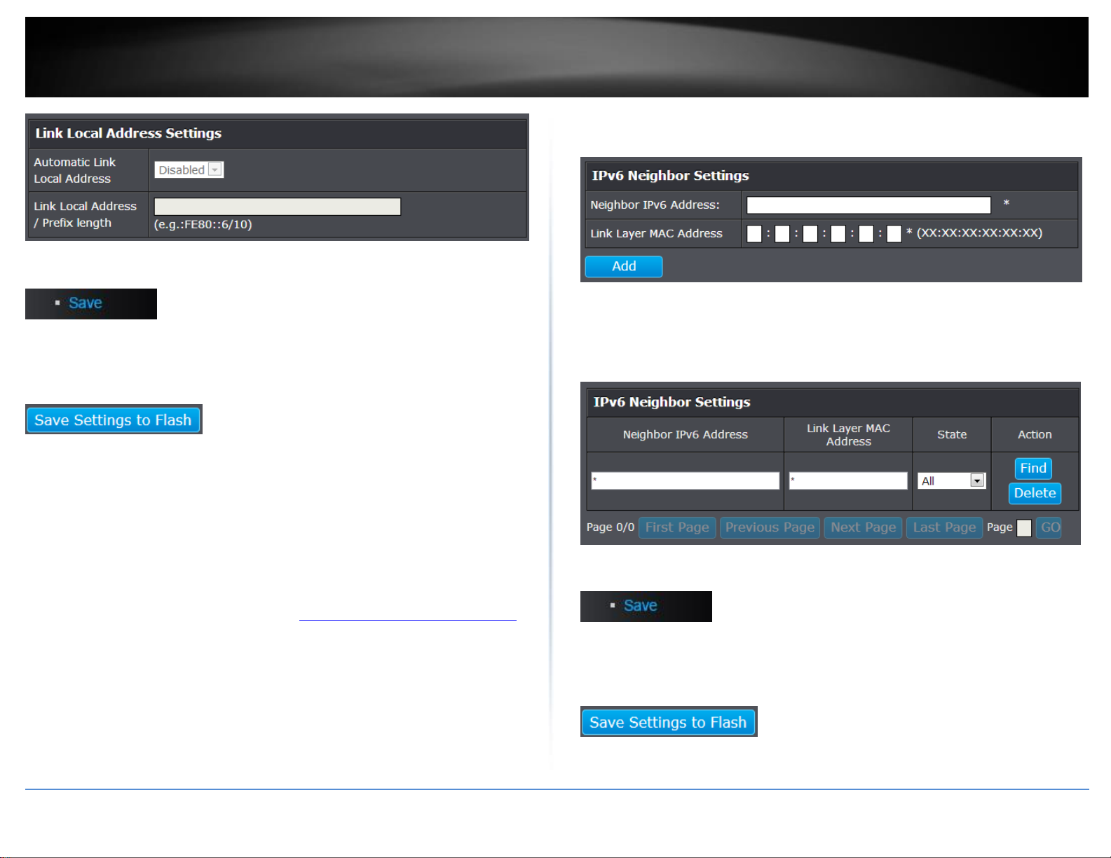
Link Local Address Settings: A link-local address is an IPv6 unicast address that
can be automatically configured on any interface using the link-local prefix
FE80::/10 (1111 1110 10) and the interface identifier in the modified EUI-64
format. Link-local addresses are used in the neighbor discovery protocol and
the stateless autoconfiguration process. Nodes on a local link can use link-local
addresses to communicate; the nodes do not need globally unique addresses
to communicate. IPv6 devices must not forward packets that have link-local
source or destination addresses to other links.
Automatic Link Local Address: A link local address has a prefix of FE80, is not
routable, and can be used for communication only on the local network. Only
one link local address is supported. If a link local address exists on the interface,
this entry replaces the address in the configuration.
Link Local Address/Prefix length: Enter the Link Local Address/Prefix Length.
© Copyright 2017 TRENDnet. All Rights Reserved.
TRENDnet User’s Guide
TEG-284WS
12
4. In the left hand panel, click Tools, click on Configuration, and click Save.
5. Click Save Settings to Flash, then click OK.
Note: This step saves all configuration changes to the NV-RAM to ensure that if the
switch is rebooted or power cycled, the configuration changes will still be applied.
Add IPv6 neighbors
System > IPv6 Neighbor
This settings allows you to manually define IPv6 supported neighboring devices on your
network.
1. Log into your switch management page (see “Access your switch management page”
on page 7).
2. Click on System, and click on IPv6 Neighbor.
3. Review the settings. When you have completed making changes, click Apply to save
the settings.
Neighbor IPv6 Address: Specifies the neighbor IPv6 address.
Link Layer MAC Address: Specifies the link layer MAC address.
Click Add to save the entry to the list.
You can type in the specific address and click Find to find the entry to modify or
click Delete or delete the address. If the entries span multiple pages, you can
navigate page number in the Page field and click Go or you can click First,
Previous, Next, and Last Page to navigate the pages.
4. In the left hand panel, click Tools, click on Configuration, and click Save.
5. Click Save Settings to Flash, then click OK.
Note: This step saves all configuration changes to the NV-RAM to ensure that if the
switch is rebooted or power cycled, the configuration changes will still be applied.
© Copyright 2017 TRENDnet. All Rights Reserved.
TRENDnet User’s Guide
TEG-284WS
13
Set your DNS server settings
System > DNS
This setting allows you to configure your IPv4/IPv6 DNS server settings for the purpose
or resolving hostnames. For example, when specifying your SNTP server time settings
via domain name, the switch will not be able to resolve the SNTP domain name specified
until you configure the switch DNS server setting.
1. Log into your switch management page (see “Access your switch management page”
on page 7).
2. Click on System, and click on DNS.
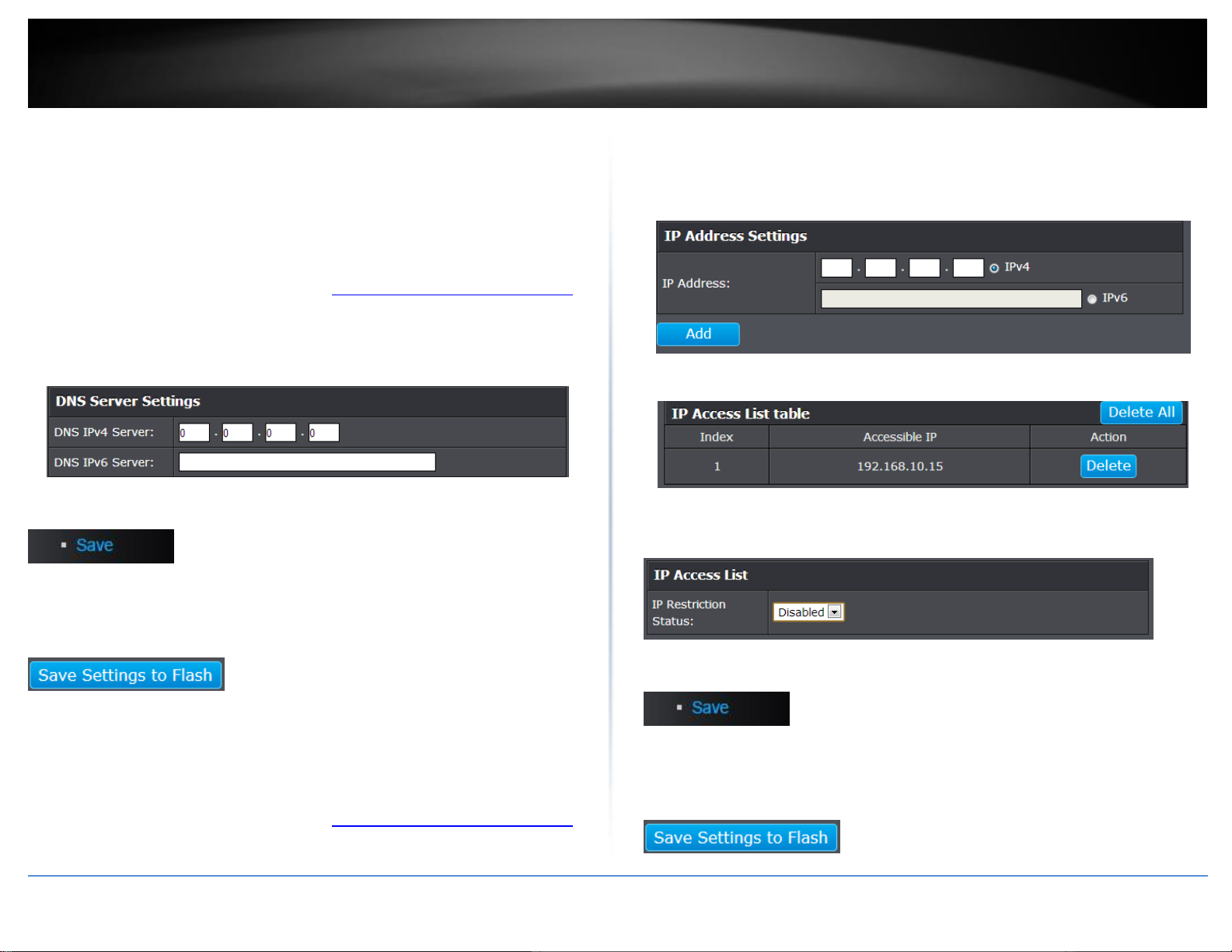
3. Enter your DNS IPv4 Server address and/or DNS IPv6 Server address in the provided
fields.
4. In the left hand panel, click Tools, click on Configuration, and click Save.
5. Click Save Settings to Flash, then click OK.
Note: This step saves all configuration changes to the NV-RAM to ensure that if the
switch is rebooted or power cycled, the configuration changes will still be applied.
Restrict access to switch management page
System > IP Access List
This section allows you to define or restrict access to the switch management page to a
list of specific IP addresses.
1. Log into your switch management page (see “Access your switch management page”
on page 7).
2. Click on System, and click on IP Access List.
3. Review the settings.
First, enter the IPv4 or IPv6 address to allow access and click Add for each entry.
For each entry, the access list will populate. You can click Delete next to the entry to
delete the entry or Delete All to delete all entries in the table.
When you have completed entering the IPv4 and IPv6 address entries, click the IP
Restriction Status drop-down list at the top and select Enabled, then click Apply.
5. In the left hand panel, click Tools, click on Configuration, and click Save.
6. Click Save Settings to Flash, then click OK.
Note: This step saves all configuration changes to the NV-RAM to ensure that if the
switch is rebooted or power cycled, the configuration changes will still be applied.
© Copyright 2017 TRENDnet. All Rights Reserved.
TRENDnet User’s Guide
TEG-284WS
14
Change administrator password and add accounts
System > Administration
This section explains how to change the administrator password create additional
administrative user accounts for access to the switch management page.
1. Log into your switch management page (see “Access your switch management page”
on page 7).
2. Click on System, and click on Administration.
3. Review the settings.
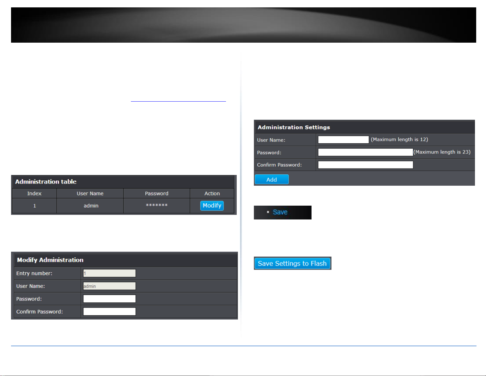
To change the administrator password, in the “admin” entry in the table, click on
Modify. Note: This default administrator account cannot be deleted.
In the Password field, enter the new password and enter the new password again the
Confirm Password field to verify. Then, click Apply.
Note: The password consists of up to 23 alphanumeric characters.
To create additional administrative user accounts:
User Name: Enter the user name of the new account.
Password: Enter the password for the new acocunt and enter the password
again the Confirm Password field to verify. Then, click Add to add to the table.
For additional user accounts, you will be provided the option to Modify or
Delete to remove the account.
Note: The password consists of up to 23 alphanumeric characters.
.
4. In the left hand panel, click Tools, click on Configuration, and click Save.
5. Click Save Settings to Flash, then click OK.
Note: This step saves all configuration changes to the NV-RAM to ensure that if the
switch is rebooted or power cycled, the configuration changes will still be applied.
© Copyright 2017 TRENDnet. All Rights Reserved.
TRENDnet User’s Guide
TEG-284WS
15
Change web idle login timeout settings
System > Timeout
This section explains how to modify the switch management page idle timeout settings.
1. Log into your switch management page (see “Access your switch management page”
on page 7).
2. Click on System, and click on Timeout.
3. Review the settings. Click Apply to save changes.
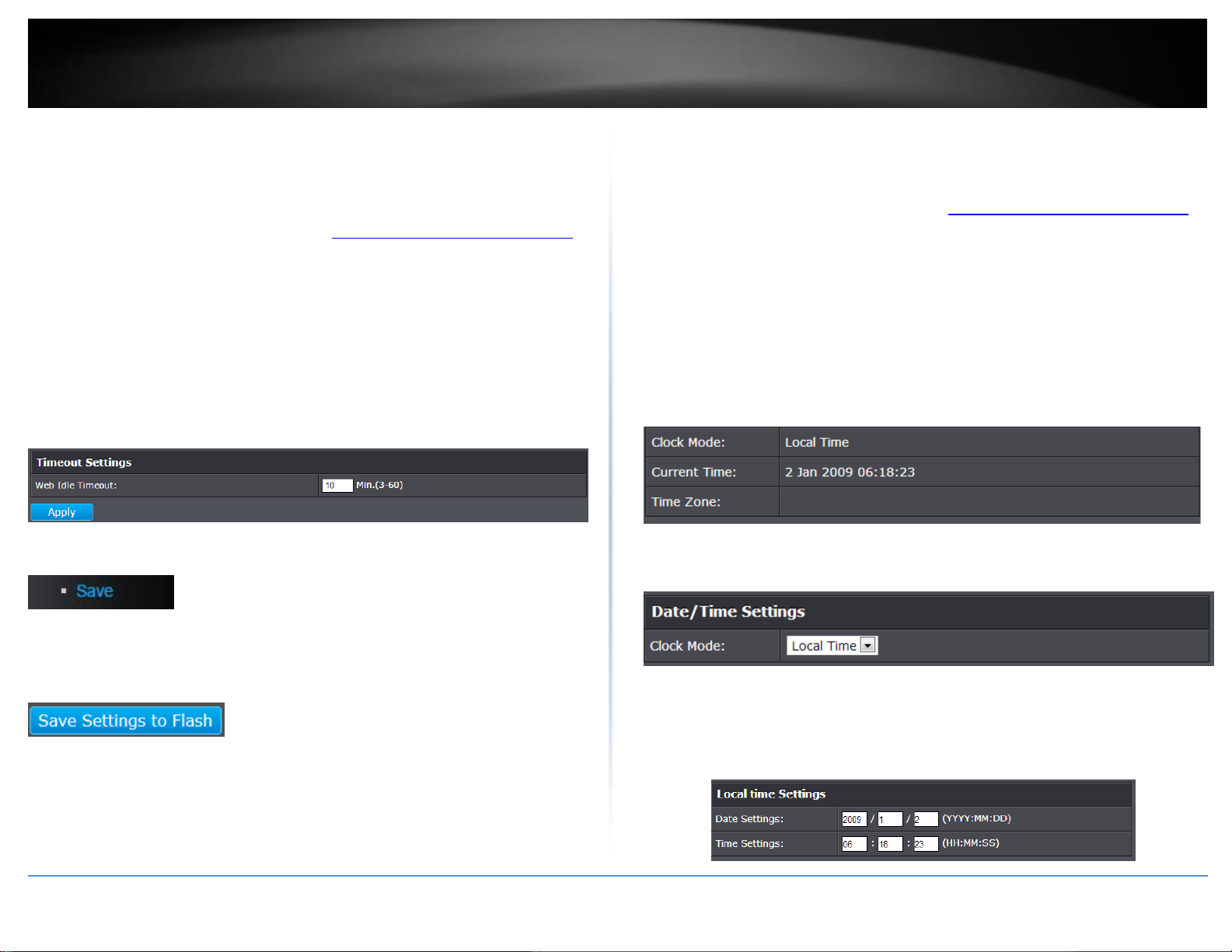
Web Idle Timeout - Enter the idle period in minutes, when the switch will
automatically log out a user from the switch management page.
4. In the left hand panel, click Tools, click on Configuration, and click Save.
5. Click Save Settings to Flash, then click OK.
Note: This step saves all configuration changes to the NV-RAM to ensure that if the
switch is rebooted or power cycled, the configuration changes will still be applied.
Set the switch date and time
System > System Time
1. Log into your switch management page (see “Access your switch management page”
on page 7).
2. Click on System, and click on System Time.
3. Review the settings. Click Apply to save changes.
Clock Mode - Displays if system time and date is set manually Local Time or
obtained automatically from a network time server SNTP.
Current Time – Displays the current system time and date.
Time Zone – Displays the current system time zone.
Clock Mode: Select Local Time to manually configure your date and time
settings or select SNTP to configure your switch to automatically obtain
settings from a network time server.
o Local Time – Allows you to manually set the time settings. If selecting
this option, under Local Time Settings, manually enter your date and
time settings.
Date Settings – Enter your date settings (YYYY/MM/DD).
Time Settings – Enter your time settings (HH:MM:SS)
© Copyright 2017 TRENDnet. All Rights Reserved.
TRENDnet User’s Guide
TEG-284WS
16
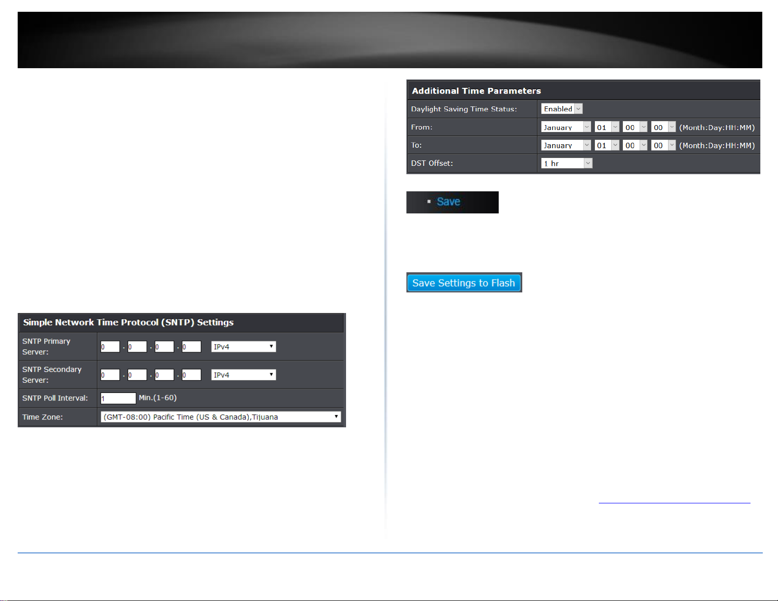
o SNTP – Allows you to configure your switch to pull time and date
settings automatically from a network time server. If selecting this
option, under Simple Network Time Protocol (SNTP) Settings, enter
your time server settings.
Note: Please note that in order for the switch to communicate to
Internet SNTP time servers, the switch must have valid IPv4/IPv6
address settings including a default gateway address for Internet
access. Additionally, if using a domain name, the switch must be
configured with valid DNS server settings in order to resolve
host/domain names.
SNTP Primary Server – Enter the primary network time server
IPv4 address, IPv6 address, or Domain Name.
SNTP Secondary Server – Enter the secondary network time
server IPv4 address, IPv6 address, or Domain Name.
SNTP Poll Interval – Enter the interval time when your switch
will update the time and date settings with the time server.
Time Zone – Click the drop-down list to select your time zone.
Additionally, you can set your Daylight Savings Time.
Additional Time Parameters – Allows you to configure additional Daylight
Saving Time parameters.
Daylight Savings Time Status: Click the drop-down list to
enable or disable Daylight Savings.
From: Set the daylight savings start date and time.
To: Set the daylight savings end date and time.
DST Offset: Click the drop-down list to set the time offset
based on respective time zone.
4. In the left hand panel, click Tools, click on Configuration, and click Save.
5. Click Save Settings to Flash, then click OK.
Note: This step saves all configuration changes to the NV-RAM to ensure that if the
switch is rebooted or power cycled, the configuration changes will still be applied.
Enable HTTPS/SSL (Secure Socket Layer) management access
System > SSL
By default, your switch management page can be accessed using standard web HTTP
protocol which is unsecure. Enabling HTTPS/SSL management access allows access to
the switch management page using secure encrypted communication which prevents
unauthorized users from intercepting user name and password credentials. Typically,
the switch is accessed within the local network only by system administrators which
does not necessarily require additional security. It is recommended to only enable this
feature, if allowing switch management access from other networks or over the
Internet.
Note: Once HTTPS/SSL management access is enabled, HTTP management access will be
disabled forcing all access to the switch management page using secure encryption
communication only.
1. Log into your switch management page (see “Access your switch management page”
on page 7).
2. Click on System, and click on SSL.
© Copyright 2017 TRENDnet. All Rights Reserved.
TRENDnet User’s Guide
TEG-284WS
17
3. Review the settings. Click Apply to save changes.
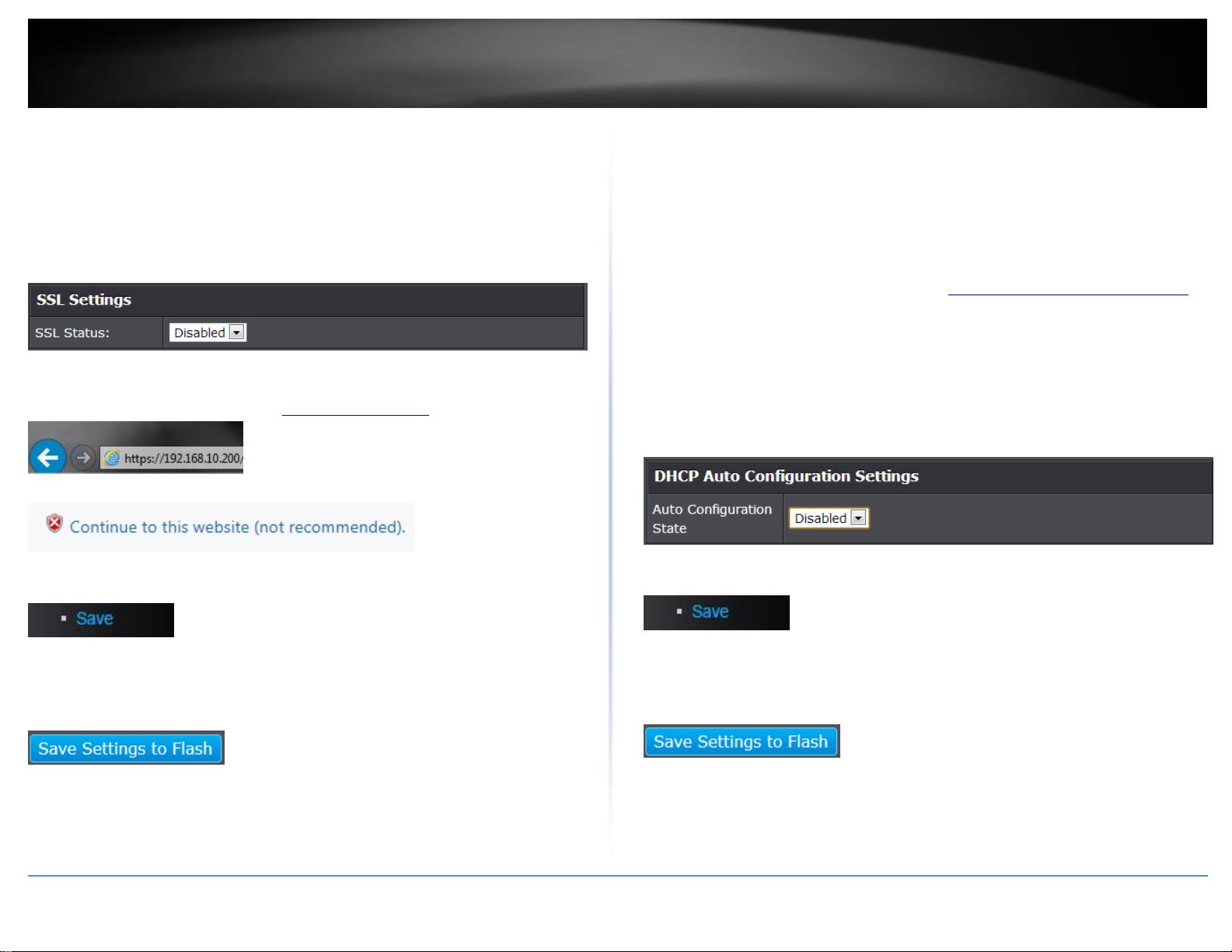
SSL Status:
o Enabled – Enables HTTPS/SSL management access and disables HTTP
unsecured mode.
o Disabled – Disabled HTTPS/SSL management access and enabled HTTP
unsecured mode. (Default setting).
If enabling SSL management access, you will need to access the switch management
page using HTTPS instead of HTTP. (e.g. https://192.168.10.200)
Click Continue, Proceed to this website, and accept the certificate if prompted.
4. In the left hand panel, click Tools, click on Configuration, and click Save.
5. Click Save Settings to Flash, then click OK.
Note: This step saves all configuration changes to the NV-RAM to ensure that if the
switch is rebooted or power cycled, the configuration changes will still be applied.
Enable DHCP Auto Configuration
System > DHCP Auto Configuration
If you need to automatically update the switch configuration files via a remote server,
the DHCP Auto Configuration feature is available for this purpose via the DHCP server.
Your IP address settings must enable the DHCP client so that this feature can operate
with your DHCP server.
1. Log into your switch management page (see “Access your switch management page”
on page 7).
2. Click on System, and click on DHCP Auto Configuration.
3. Click the Auto Configuration State drop-down list and select Enabled. Click Apply to
save changes.
4. In the left hand panel, click Tools, click on Configuration, and click Save.
5. Click Save Settings to Flash, then click OK.
Note: This step saves all configuration changes to the NV-RAM to ensure that if the
switch is rebooted or power cycled, the configuration changes will still be applied.
© Copyright 2017 TRENDnet. All Rights Reserved.
TRENDnet User’s Guide
TEG-284WS
18
View and setup your switch logging
System > System Log
The system log is designed to monitor the operation the switch by recording the event
messages it generates during normal operation. These events may provide vital
information about system activity that can help in the identification and solutions of
system problems.
1. Log into your switch management page (see “Access your switch management page”
on page 7).
2. Click on System, and click on System Log.
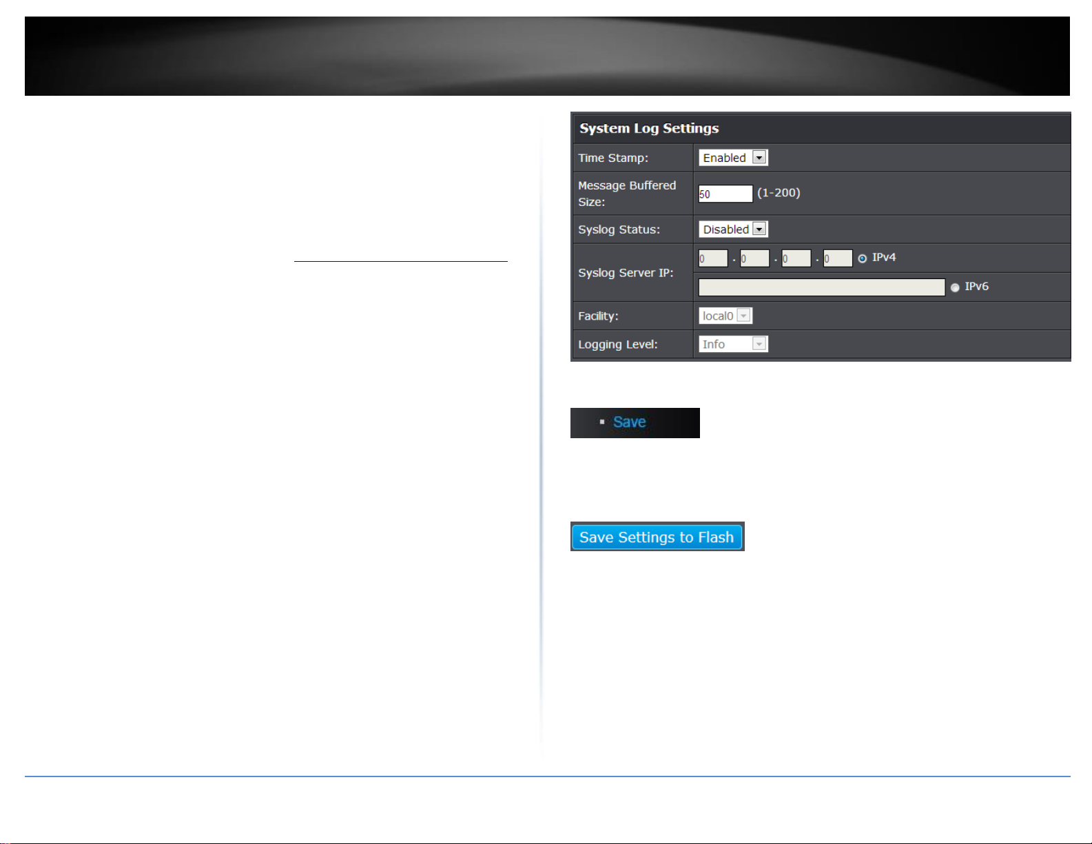
3. Review the settings. Click Apply to save changes.
Time Stamp
o Enable - Each event message recorded in the log will have a time
stamp.
o Disable - No time stamp will be included with the event messages.
Message Buffered Size - Enter the message buffer size. (Range: 1-200)
Syslog Status - Allows you to send device logging to an external log (Syslog)
server for troubleshooting or monitoring.
o Enable – Enable syslog and in the Syslog Server IP section, enter the
IPv4 or IPv6 address of the external syslog server to send logging.
o Disable – Disable syslog functionality.
Facility - Click the drop-down list and which facility to store the logging.
(Options: local0 – local7)
Note: You can define the facility to store logging on your external syslog server.
This helps to ensure you have separate logging sections for different devices.
Logging Level – Click the drop-down list to select what level of event messages
that will be logged.
1 Alert - Action must be taken immediately.
2 Critical - Critical conditions are displayed.
3 Warning - Warning conditions are displayed.
4 Info - Informational messages are displayed.
4. In the left hand panel, click Tools, click on Configuration, and click Save.
5. Click Save Settings to Flash, then click OK.
Note: This step saves all configuration changes to the NV-RAM to ensure that if the
switch is rebooted or power cycled, the configuration changes will still be applied.

© Copyright 2017 TRENDnet. All Rights Reserved.
TRENDnet User’s Guide
TEG-284WS
19
Enable or Disable SNMP
System > SNMP > Settings
You can manage a switch by viewing and configuring the management information base
(MIB) objects on the device with the Simple Network Management Program (SNMP).
This chapter describes how to configure SNMP. A Group Name, IP address of the switch
and at least one community string is the minimum required to manage the switch using
SNMP.
Note: If you disable the SNMP on the switch, the switch will not be manageable via
SNMP using MIBs.
1. Log into your switch management page (see “Access your switch management page”
on page 7).
2. Click on System, click on SNMP, and click on Settings.
3. Review the settings. Click Apply to save changes.
SNMP Agent Status: Click the drop-down list to one of the following options.
o Enabled - When you enable this parameter, the SNMP agent is active.
You can manage the switch with SNMP network management
software and the switch’s private MIB.
o Disabled - When you enable this parameter, the SNMP agent is
inactive.
4. Click Save Settings to Flash (menu).
5. Click Save Settings to Flash (button), then click OK.
Note: This step saves all configuration changes to the NV-RAM to ensure that if the
switch is rebooted or power cycled, the configuration changes will still be applied.
Set the SNMP Engine ID
System > SNMP > Settings
The SNMP Engine ID screen allows network managers to define the SNMP Engine ID or
to assign the default Engine ID to SNMP.
1. Log into your switch management page (see “Access your switch management page”
on page 7).
2. Click on System, click on SNMP, and click on Settings.
3. Review the settings. Click Apply to save the settings.
Engine ID (10-64 Hex Characters) – Enter the local device Engine ID. The field
value is a hexadecimal string. Each byte in hexadecimal character strings is two
hexadecimal digits. The Engine ID must be defined before SNMP is enabled.
Reset to Default – Use the device-generated Engine ID (Reset to Default will
override any entry in the Engine ID field).
4. In the left hand panel, click Tools, click on Configuration, and click Save.
5. Click Save Settings to Flash, then click OK.
Note: This step saves all configuration changes to the NV-RAM to ensure that if the
switch is rebooted or power cycled, the configuration changes will still be applied.
© Copyright 2017 TRENDnet. All Rights Reserved.
TRENDnet User’s Guide
TEG-284WS
20
Configure the SNMP View Table
System > SNMP > View
The SNMP View table specifies the MIB object access criteria for each View Name. If the
View Name is not specified on this page, then it has access to all MIB objects. You can
specify specific areas of the MIB that can be accessed or denied based on the entries in
this table. You can create and delete entries in the View table.
1. Log into your switch management page (see “Access your switch management page”
on page 7).
2. Click on System, click on SNMP, and click on View.
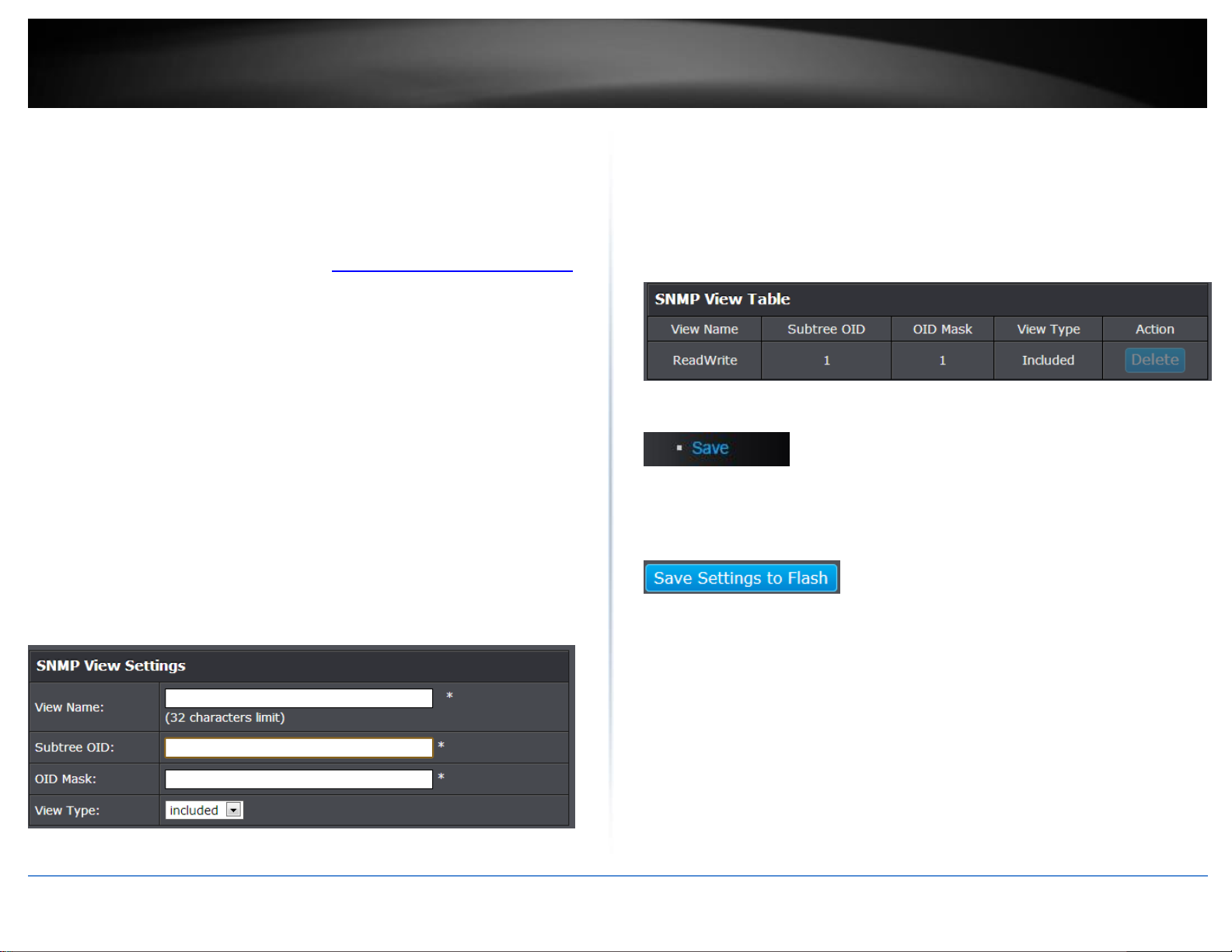
3. Review the settings.
Creating SNMP View Table Entries
This procedure explains how to create entries in the SNMP View Table.
Enter the View Name. This entry must be pre-defined on the SNMP
User/Group page.
Enter the Subtree OID.
Enter “1” for the OID Mask.
Enter the View Type. Choose from the following options, and then click Add.
o Included: This selection allows the specified MIB object to be included
in the view.
o Excluded: This selection blocks the view of the specified MIB object.
Modifying SNMP View Table Entries
If you need to modify an entry in the View Table page, you must first delete the entry
and then re-enter it.
Deleting SNMP View Table Entries
In the Action column of the table, click Delete for the View table entry that you want to
remove.
4. In the left hand panel, click Tools, click on Configuration, and click Save.
5. Click Save Settings to Flash, then click OK.
Note: This step saves all configuration changes to the NV-RAM to ensure that if the
switch is rebooted or power cycled, the configuration changes will still be applied.

© Copyright 2017 TRENDnet. All Rights Reserved.
TRENDnet User’s Guide
TEG-284WS
21
Configure the SNMP Group Access Table
System > SNMP > Group
The SNMP View Names are defined in the SNMP Group Access table and are based on
the User and Group Names
1. Log into your switch management page (see “Access your switch management page”
on page 7).
2. Click on System, click on SNMP, and click on Group.
3. Review the settings.
Creating SNMP View Names
Before you can create an SNMP View name, you must define a Group Name using the
SNMP User/Group page.
Enter the Group Name. This entry must be pre-defined on the SNMP
User/Group page.
Enter the Read View Name. This name is an optional field. It can be up to 31
characters in length.
Enter the Write View Name. This name is an optional field. It can be up to 31
characters in length.
Enter the Notify View Name. This name is an optional field. It can be up to 31
characters in length.
From the Security Model pull-down menu, select v3.
Enter the Security Level from the pull-down menu. The selection options are:
o NoAuthNoPriv: This selection is the appropriate selection when no
Auth-Protocol or Priv-Protocol (no encryption) are selected on the
SNMP User/Group page.
o AuthNoPriv: Choose this selection when encryption has been enabled
but only the Auth-Protocol has a password assigned and the Priv-
Protocol has been selected as none on the SNMP User/Group page.
o AuthPriv: When the Auth-Protocol or Priv-Protocol have been
enabled, choose this selection.
Click the Add button.
Modifying SNMP View Names
If you need to modify an entry in the SNMP Group Access page, you must first delete the
entry and then re-enter it.
Deleting SNMP View Names
In the Action column of the table, click Delete for the View Name that you want to
remove.
Note: The views corresponding to the ReadOnly and ReadWrite Group Names are
default values and cannot be removed.
5. In the left hand panel, click Tools, click on Configuration, and click Save.
6. Click Save Settings to Flash, then click OK.
Note: This step saves all configuration changes to the NV-RAM to ensure that if the
switch is rebooted or power cycled, the configuration changes will still be applied.

© Copyright 2017 TRENDnet. All Rights Reserved.
TRENDnet User’s Guide
TEG-284WS
22
Configure the SNMP User/Group Table
System > SNMP > User
An SNMP User Name and Group Name definition is the basis for all the other SNMP
tables. You can create and delete View Names by following the procedures in the
following sections:
1. Log into your switch management page (see “Access your switch management page”
on page 7).
2. Click on System, click on SNMP, and click on User.
3. Review the settings.
Creating SNMP User and Group Names
Note: There are no default User Names or Group Names defined for SNMP.
Type a new User Name. Enter a name up to 32 characters in length.
Type a new Group Name. Enter a name up to 32 characters in length.
From the SNMP Version pull down menu, select v3. The encryption check-box
becomes active.
o Check the encryption check-box. The Auth-Protocol, Priv-Protocol,
and associated password fields become active.
Select one of the following choices for the Auth-Protocol field:
o MD5 - The MD5 authentication protocol. SNMP Users are
authenticated with the MD5 authentication protocol after a message
is received.
o SHA - The SHA authentication protocol. Users are authenticated with
the SHA authentication protocol after a message is received.
Enter the password for the Auth-Protocol.
Select one of the following choices for the Priv-Protocol field:
o DES - Specifies DES encryption scrambles the SNMP data so that
outside observers are prevented from seeing the data content.
o none - Specifies no encryption is applied to SNMP data.
Click Add. The new User Name and Group Name are displayed on the SNMP
User/Group page.
Modifying SNMP User and Group Names
If you need to modify an entry in the SNMP User/Group page, you must first delete the
entry and then re-enter it.
Deleting SNMP User and Group Names
In the Action column of the table, click Delete for the User Name and Group Name that
you want to remove.
5. In the left hand panel, click Tools, click on Configuration, and click Save.
6. Click Save Settings to Flash, then click OK.
Note: This step saves all configuration changes to the NV-RAM to ensure that if the
switch is rebooted or power cycled, the configuration changes will still be applied.
© Copyright 2017 TRENDnet. All Rights Reserved.
TRENDnet User’s Guide
TEG-284WS
23
Configure the SNMP Community Table
System > SNMP > Community
A community string has attributes for controlling who can use the string and what the
string will allow a network management station to do on the switch. The Web
Management Utility does not provide any default community strings. You must first
define an SNMP User and Group Name on the SNMP User/Group page and then define a
Community Name on the SNMP Community Table page.
1. Log into your switch management page (see “Access your switch management page”
on page 7).
2. Click on System, click on SNMP, and click on Community.
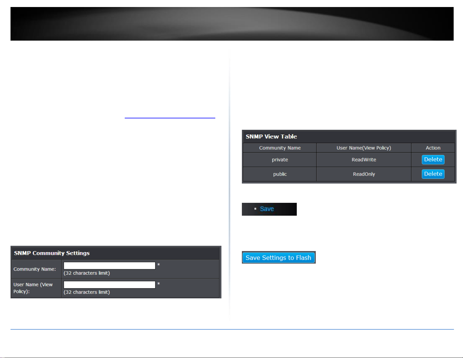
3. Review the settings.
Create SNMP Community Settings
Enter a new Community Name. A name can be up to 31 characters in length.
Enter a User Name(View Policy) that has been previously defined. This name
must match one of the User Names displayed on the
Note: SNMP User/Group page. If you enter a user name that has not been pre-
defined on the SNMP User/Group page, the Community entry is displayed, but
the agent/manager communication fails.
Click Add. The values of the new Community Name and User Name are
displayed.
Modify SNMP Community Settings
If you need to modify a Community Table entry, you must first delete the entry by using
the procedure below and then re-enter it with the modification by creating a new
Community table entry.
Delete SNMP Community Settings
To delete a Community Name, click Delete next to the entry in the table that
you want to remove.
The deleted Community Name is no longer displayed in the Community table.
No confirmation message is displayed.
4. In the left hand panel, click Tools, click on Configuration, and click Save.
5. Click Save Settings to Flash, then click OK.
Note: This step saves all configuration changes to the NV-RAM to ensure that if the
switch is rebooted or power cycled, the configuration changes will still be applied.
© Copyright 2017 TRENDnet. All Rights Reserved.
TRENDnet User’s Guide
TEG-284WS
24
Configure the SNMP Trap Management
System > SNMP > Trap
A Host IP address is used to specify a management device that needs to receive SNMP
traps sent by the switch. This IP address is associated with the SNMP Version and a valid
Community Name in the Host table of the switch.
1. Log into your switch management page (see “Access your switch management page”
on page 7).
2. Click on System, click on SNMP, and click on Trap.
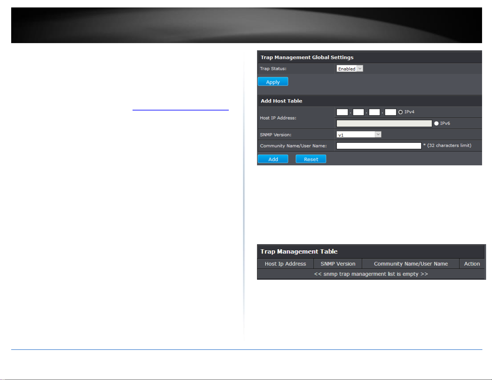
3. Review the settings.
Create Trap Host Table Entry
Use the following procedure to create a trap Host table entry:
Enable trap management by selecting the radio button next to Enabled at the
top of the page. By default, trap management is enabled.
Enter the Host IP Address for the management device that is to receive the
SNMP traps.
Enter the SNMP Version, either v1 or v2c, that is configured for the host
management device.
Enter a Community Name that you have defined previously in the SNMP
Community table. The Community Name must correlate with one of the
communities displayed on the SNMP Community Table page. If you enter a
Community Name that has not been pre-defined, the Trap Host entry is
displayed, but agent/manager communication fails.
Click Add. The new host is added to the table.
Modify a Trap Host Table Entry
If you need to modify an SNMP Trap entry, you must first delete the entry by using the
procedure below and then re-enter it with the modification by creating a new SNMP
trap.
Delete a Trap Host Table Entry
To delete an entry in the host table, click Delete next to the entry in the table that you
want to remove. The Host table entry is removed from the table. No confirmation
message is displayed.
5. In the left hand panel, click Tools, click on Configuration, and click Save.
6. Click Save Settings to Flash, then click OK.
Note: This step saves all configuration changes to the NV-RAM to ensure that if the
switch is rebooted or power cycled, the configuration changes will still be applied.
© Copyright 2017 TRENDnet. All Rights Reserved.
TRENDnet User’s Guide
TEG-284WS
25
Enable or Disable RMON
System > RMON > Settings
The RMON (Remote MONitoring) MIB is used with SNMP applications to monitor the
operations of network devices. The Switch supports the four RMON MIB groups listed
here:
Statistic group— This group is used to view port statistics remotely with SNMP
programs.
History group— This group is used to collect histories of port statistics to
identify traffic trends or patterns.
Event group— This group is used with alarms to define the actions of the
switch when packet statistic thresholds are crossed.
Alarm group—This group is used to create alarms that trigger event log
messages or SNMP traps when statistics thresholds are exceeded.
You can use your SNMP Network Management System (NMS) software and the RMON
section of the MIB tree to view the RMON statistics, history and alarms associated with
specific ports. Since RMON uses the SNMP agent for communicating with your NMS
software, the SNMP Agent must be enabled and the SNMP feature must be configured
on your switch. Since RMON works in conjunction with the SNMP agent, the SNMP
agent must be enabled for the RMON feature to be active.
1. Log into your switch management page (see “Access your switch management page”
on page 7).
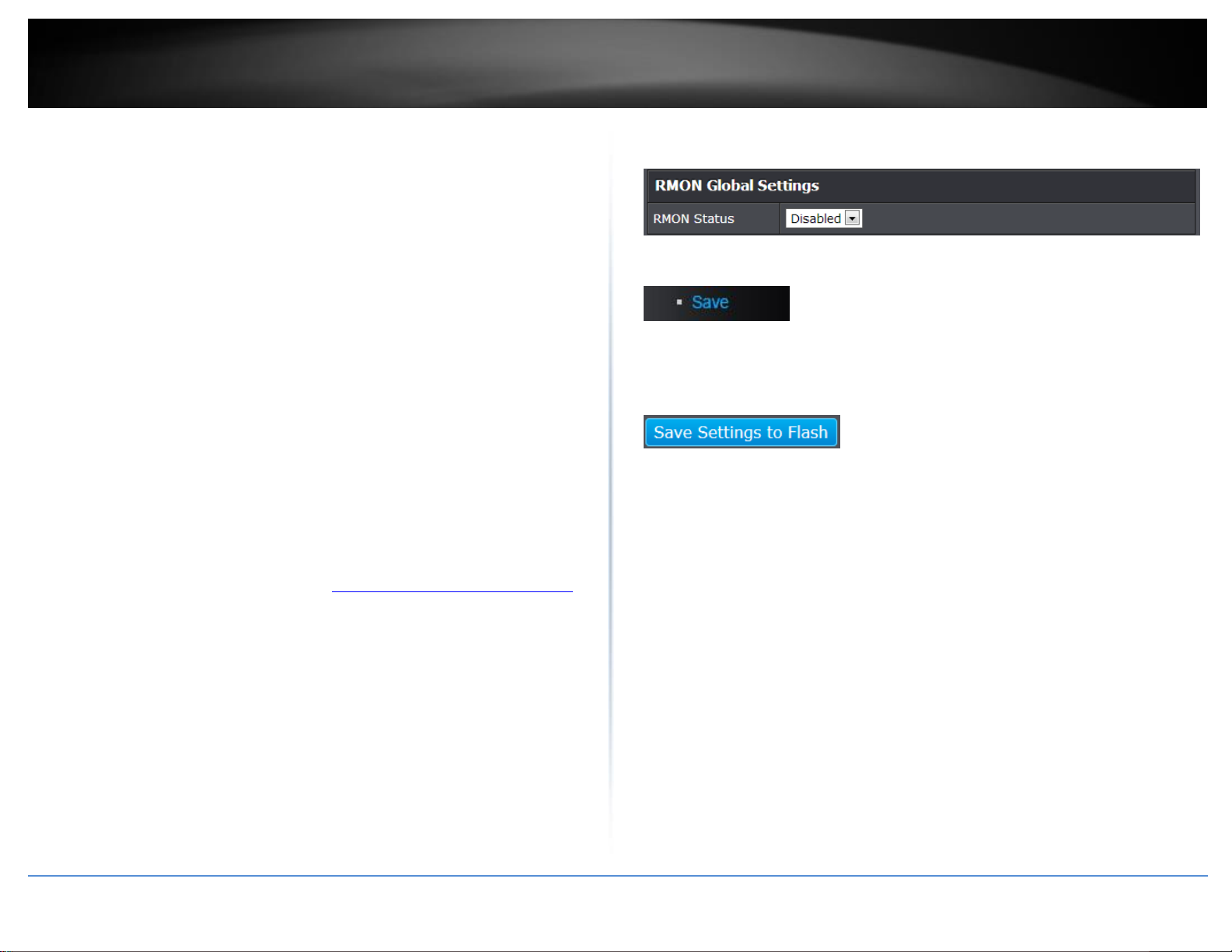
2. Click on System, click on RMON and click on Settings.
3. Click the RMON Status drop-down list and select Enabled to enable RMON. Click
Apply to save settings.
4. In the left hand panel, click Tools, click on Configuration, and click Save.
5. Click Save Settings to Flash, then click OK.
Note: This step saves all configuration changes to the NV-RAM to ensure that if the
switch is rebooted or power cycled, the configuration changes will still be applied.
© Copyright 2017 TRENDnet. All Rights Reserved.
TRENDnet User’s Guide
TEG-284WS
26
Configure parameters for RMON Ethernet statistics
System > RMON > Statistics
You can remotely view individual port statistics with RMON by using your SNMP NMS
software and the RMON portion of the MIB tree.
1. Log into your switch management page (see “Access your switch management page”
on page 7).
2. Click on System, click on RMON, and click on Statistics.
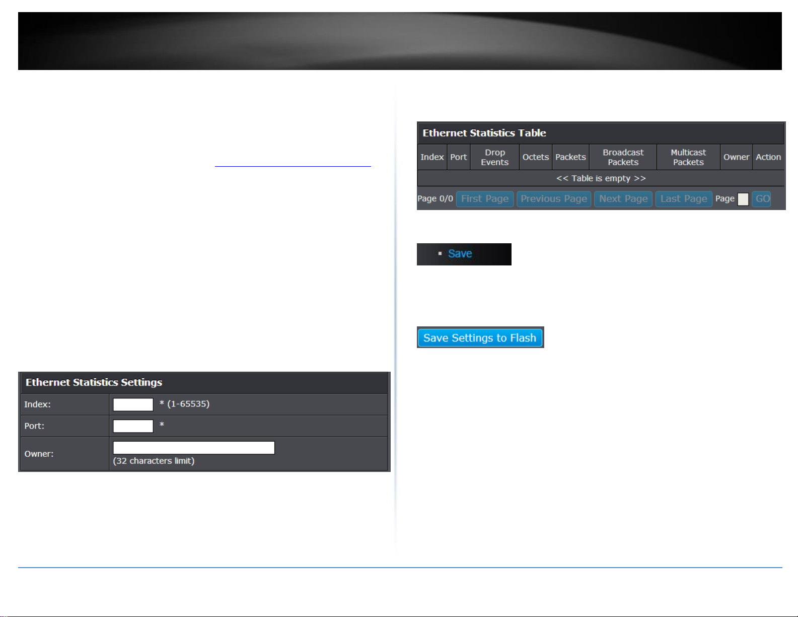
3. Review the settings.
Index: This parameter specifies the ID number of the new group. The range is 1
to 65535.
Port: This parameter specifies the port where you want to monitor the
statistical information of the Ethernet traffic.
Owner: This parameter is used to identify the person who created an entry. It is
primarily intended for switches that are managed by more than one person,
and is an optional field.
Click Add to add the entry to the table.
In the list, you can click Modify to modify an entry or click Delete or delete the entry. If
the entries span multiple pages, you can navigate page number in the Page field and
click Go or you can click First, Previous, Next, and Last Page to navigate the pages.
4. In the left hand panel, click Tools, click on Configuration, and click Save.
5. Click Save Settings to Flash, then click OK.
Note: This step saves all configuration changes to the NV-RAM to ensure that if the
switch is rebooted or power cycled, the configuration changes will still be applied.

© Copyright 2017 TRENDnet. All Rights Reserved.
TRENDnet User’s Guide
TEG-284WS
27
Configure parameters for RMON history control settings
System > RMON > History
RMON histories are snapshots of port statistics. They are taken by the switch at
predefined intervals and can be used to identify trends or patterns in the numbers or
types of ingress packets on the ports on the switch. The snapshots can be viewed with
your SNMP NMS software with the history group of the RMON portion of the MIB tree.
A history group is divided into buckets. Each bucket stores one snapshot of statistics of a
port. A group can have from 1 to 50 buckets. The more buckets in a group, the more
snapshots it can store.
1. Log into your switch management page (see “Access your switch management page”
on page 7).
2. Click on System, click on RMON, and click on History.
3. Review the settings.
Index: This parameter specifies the ID number of the new group. The range is 1
to 65535.
Port: This parameter specifies the port where you want to monitor the
statistical information of the Ethernet traffic.
Buckets Requested: This parameter defines the number of snapshots of the
statistics for the port. Each bucket can store one snapshot of RMON statistics.
Different ports can have different numbers of buckets. The range is 1 to 50
buckets.
Interval: This parameter specifies how frequently the switch takes snapshots of
the port’s statistics. The range is 1 to 3600 seconds (1 hour). For example, if
you want the switch to take one snapshot every minute on a port, you specify
an interval of sixty seconds.
Owner: This parameter is used to identify the person who created an entry. It is
primarily intended for switches that are managed by more than one person,
and is an optional field.
Click Add to add the entry to the table.
In the list, you can click Modify to modify an entry or click Delete or delete the entry.
You can also click Delete All to delete all of the entries in the table. If the entries span
multiple pages, you can navigate page number in the Page field and click Go or you can
click First, Previous, Next, and Last Page to navigate the pages.
4. In the left hand panel, click Tools, click on Configuration, and click Save.
5. Click Save Settings to Flash, then click OK.
Note: This step saves all configuration changes to the NV-RAM to ensure that if the
switch is rebooted or power cycled, the configuration changes will still be applied.
 Loading...