


 Loading...
TRENDnet User’s Guide |
|
Contents |
|
Introduction ........................................................................................................... |
4 |
Package Contents .......................................................................................................... |
4 |
Hardware Feature.......................................................................................................... |
5 |
System Concept...................................................................................................... |
6 |
Product Benefit.............................................................................................................. |
7 |
Installation Considerations ............................................................................................ |
7 |
Installation ..................................................................................................................... |
7 |
Configuration ................................................................................................................. |
8 |
Applications ........................................................................................................... |
9 |
AP Mode (including Access Point + WDS)...................................................................... |
9 |
WDS Mode (Pure WDS) ............................................................................................... |
10 |
Client Bridge + Universal Repeater Mode ................................................................... |
10 |
CPE + AP Mode (Router Client + Access Point) ............................................................ |
11 |
Web Management Interface Instructions............................................................. |
11 |
AP Mode Configuration........................................................................................ |
12 |
External Network Connection...................................................................................... |
12 |
Network Requirement ................................................................................................. |
12 |
Configure LAN IP ...................................................................................................... |
12 |
Wireless LAN Network ................................................................................................. |
15 |
Wireless General Setup............................................................................................ |
15 |
Wireless Advanced Setup......................................................................................... |
15 |
Wireless WMM QoS Setup....................................................................................... |
17 |
Create Virtual AP (VAP) ............................................................................................ |
19 |
Virtual AP Setup ....................................................................................................... |
20 |
Wireless MAC Filter Setup........................................................................................ |
22 |
Wireless Network Expansion ................................................................................... |
22 |
System Status .............................................................................................................. |
23 |
System Overview...................................................................................................... |
23 |
Associated Clients Status ......................................................................................... |
24 |
Show WDS Link Status.............................................................................................. |
24 |
|
Table of Contents |
Extra Information..................................................................................................... |
25 |
Event Log.................................................................................................................. |
26 |
WDS Mode Configuration..................................................................................... |
26 |
External Network Connection ..................................................................................... |
26 |
Network Requirement ............................................................................................. |
26 |
Configure LAN IP ...................................................................................................... |
27 |
Wireless Network Expansion ....................................................................................... |
27 |
Wireless General Setup............................................................................................ |
27 |
Wireless Advanced Setup......................................................................................... |
28 |
Wireless WMM QoS Setup....................................................................................... |
29 |
WDS Setup ............................................................................................................... |
31 |
System Status .............................................................................................................. |
32 |
System Overview ..................................................................................................... |
32 |
Extra Information..................................................................................................... |
33 |
Event Log.................................................................................................................. |
34 |
WDS Link Status ....................................................................................................... |
34 |
Repeater Mode .................................................................................................... |
35 |
External Network Connection ..................................................................................... |
35 |
Network Requirement ............................................................................................. |
35 |
Configure LAN IP ...................................................................................................... |
35 |
Wireless Network Expansion ....................................................................................... |
36 |
Wireless General Setup............................................................................................ |
36 |
Wireless Advanced Setup......................................................................................... |
37 |
Wireless WMM QoS Setup....................................................................................... |
39 |
Site Survey ............................................................................................................... |
40 |
Repeater AP Setup ................................................................................................... |
41 |
Wireless MAC Filter Setup ....................................................................................... |
43 |
Create Wireless Profile ............................................................................................ |
43 |
Bandwidth Control................................................................................................... |
45 |
Configure SNMP Setup............................................................................................. |
45 |
Configure Time Policy .............................................................................................. |
46 |
System Status .............................................................................................................. |
47 |
© Copyright 2014TRENDnet. All Rights Reserved.
2

TRENDnet User’s Guide |
|
|
Table of Contents |
|
System Overview...................................................................................................... |
47 |
Remote AP status..................................................................................................... |
68 |
|
DHCP Client .............................................................................................................. |
48 |
System Management |
68 |
|
Extra Information |
48 |
|||
Configure Management |
68 |
|||
Event Log.................................................................................................................. |
49 |
|||
Associated Client List ............................................................................................... |
49 |
Configure System Time ............................................................................................ |
70 |
|
Remote AP status..................................................................................................... |
50 |
Configure SNMP Setup............................................................................................. |
70 |
|
CPE + AP Mode Configuration |
50 |
Enable UPNP ............................................................................................................ |
71 |
|
Backup / Restore and Reset to Factory |
71 |
|||
|
|
|||
External Network Connection...................................................................................... |
50 |
Firmware Upgrade ................................................................................................... |
72 |
|
Network Requirement |
50 |
Network Utility......................................................................................................... |
72 |
|
Reboot |
73 |
|||
Configure CPE Setup |
51 |
|||
Mounting bracket installation |
73 |
|||
Configure DDNS Setup ............................................................................................. |
52 |
|||
Configure LAN IP ...................................................................................................... |
53 |
Package contents |
73 |
|
Configure Static IP address |
54 |
|||
Wall mount bracket |
74 |
|||
|
|
|||
Access Point Association.............................................................................................. |
54 |
Pole mount bracket ..................................................................................................... |
74 |
|
Wireless General Setup............................................................................................ |
54 |
Appendix.............................................................................................................. |
75 |
|
Wireless Advanced Setup......................................................................................... |
55 |
Windows TCP/IP Settings |
75 |
|
Wireless WMM QoS Setup |
56 |
|||
Enabling UPnP in Windows XP |
76 |
|||
Site Survey |
58 |
|||
Limited Warranty |
78 |
|||
Create Wireless Profile |
58 |
|||
|
|
|||
AP Setup................................................................................................................... |
60 |
|
|
|
Wireless AP MAC Filter Setup .................................................................................. |
62 |
|
|
|
Access Control ............................................................................................................. |
62 |
|
|
|
DMZ.......................................................................................................................... |
62 |
|
|
|
IP Filter Setup ........................................................................................................... |
63 |
|
|
|
MAC Filter Setup ...................................................................................................... |
63 |
|
|
|
Virtual Server ........................................................................................................... |
64 |
|
|
|
Bandwidth Control ................................................................................................... |
64 |
|
|
|
Routing..................................................................................................................... |
65 |
|
|
|
Status ........................................................................................................................... |
65 |
|
|
|
System Overview...................................................................................................... |
65 |
|
|
|
DHCP Client .............................................................................................................. |
66 |
|
|
|
Extra Information ..................................................................................................... |
67 |
|
|
|
Event Log.................................................................................................................. |
68 |
|
|
|
Associated Client List ............................................................................................... |
68 |
|
|
© Copyright 2014TRENDnet. All Rights Reserved.
3

TRENDnet User’s Guide
Introduction
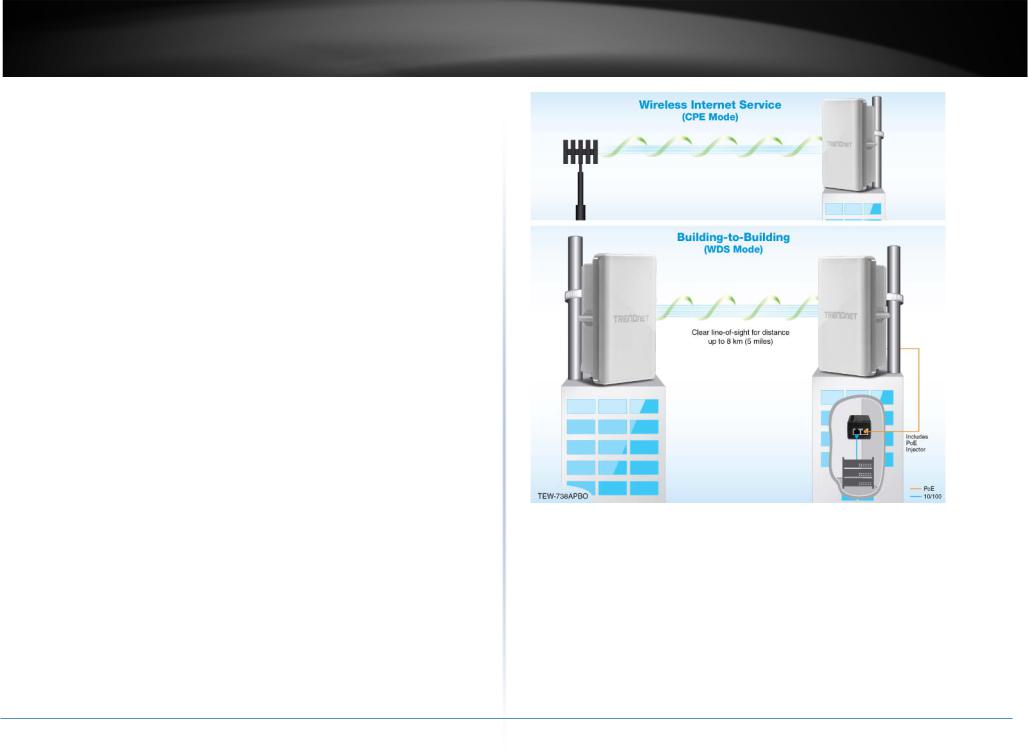
TRENDnet’s 10 dBi Outdoor PoE Access Point, model TEW-738APBO, provides Wireless N300 building-to-building connectivity for clear line of sight distances of up to 8 km (5 miles)*. A variety of installation scenarios are facilitated with Access Point (AP), Wireless Distribution System (WDS), Repeater, and CPE + AP modes. The rugged aluminum IP67 rated housing comes with wall and pole mounting hardware.
Performance
Multi-Mode Support
Supports Access Point (AP), Wireless Distribution System (WDS), WDS + AP, and CPE + AP modes
Wireless N300 (2.4 GHz)
Compliant with 802.11n/g/b technology (2.4 GHz) with data rates up to 300 Mbps
Outdoor Rated
Durable aluminum enclosure with an IP67 outdoor weather rating
Directional Antenna
Built in 10 dBi directional antenna
Distance Rating
When networked to the same unit, this unit is rated for connecting over clear line-of-sight distances of up to 8 km (5 miles)*
Power over Ethernet (PoE)
Comes with a proprietary PoE injector, so that it can connect a regular non-PoE switch
Logs
Real time logs and statistics help troubleshooting
Encrypted Wireless
Support for wireless encryption of up to WPA2
TEW-738APBO
Multiple SSIDs
Create up to seven additional SSIDs
Compatibility
Compatible with legacy wireless devices
Mounting Hardware
Pole and wall mount hardware included
* Effective wireless coverage may vary depending on the wireless device's output power, antenna gain, antenna alignment, receiving sensitivity, and radio interference. Additionally environmental factors such as weather conditions, physical obstacles, and other considerations may affect performance. For optimal results, we recommended consulting a professional installer for site survey, safety precautions, and proper installation.
**Recommended max. PoE cable length of 70 m
Package Contents
The standard package contents
•TEW-738APBO
•Multi-Language Quick Installation Guide
•CD-ROM (User’s Guide)
•PoE Injector &Power cord (All in one type)
•Mounting Kit
•Grounding wire
•Waterproof kit
© Copyright 2014TRENDnet. All Rights Reserved.
4

TRENDnet User’s Guide |
TEW-738APBO |
Hardware Feature
Bottom Panel
Front Panel
Housing |
LAN/WLAN/PWR |
PoE Port |
|
LEDs |
|||
|
Reset Button
|
• LED |
|
o LAN: Turns on when there is a LAN connection and blinks when data is running |
|
through the LAN port. |
|
o WLAN: Turns on when wireless is enabled and blinks during wireless transmission |
|
occur. |
|
o PWR: Indicates the unit is powered on. |
|
• Reset Button (unscrew cap) |
|
o Reboot: Press and hold the reset button for 2 seconds to restart the unit. All LEDs |
|
except PWR will turn off before the unit turns back on and wireless transmission |
• Housing: IP 66/67 housing |
occur. |
o Reset – Press and hold the reset button for more than 10 seconds to restore the |
|
|
unit back to factory default settings. |
|
• PoE Port (unscrew cap) – Connect the network cable that is connected to the |
|
provided PoE injector to power and configure the unit. |
© Copyright 2014TRENDnet. All Rights Reserved.
5
TRENDnet User’s Guide
System Concept
The TEW-738APBO is not only designed and used as a traditional outdoor AP, but also with rich features tailored for WISP applications. The two-level management capability and access control ease WISP and owners to maintain and manage wireless network in a more controllable fashion. Main applications are listed as follows with illustration:
•Wireless CPE for Multi Dwelling Unit/Multi-Tenant Unit (MDU/MTU) complexes including apartments, dormitories, and office complexes.
•Outdoor Access Point for school campuses, enterprise campuses, or manufacture plants.
•Indoor Access Point for hotels, factories, or warehouses where industrial grade devices are preferred.
•Public hotspot operation for café, parks, convention centers, shopping malls, or airports.
•Wireless coverage for indoor and outdoor grounds in private resorts, home yards, or gulf course communities.
© Copyright 2014TRENDnet. All Rights Reserved.
TEW-738APBO
6

TRENDnet User’s Guide
Product Benefit
The 10 dBi Outdoor PoE Access Point is the point of connection to Wireless Outdoor Network for service provider deploying last mile services to business or residential broadband subscribers.. Network administrators can create multiple subscriber service tier using per-subscriber rate limiting features, and manage centrally.
Installation Considerations
There are a number of factors that can impact the range of wireless devices.
1.Adjust your wireless devices so that the signal is traveling in a straight path, rather than at an angle. The more material the signal has to pass through the more signal you will lose.
2.Keep the number of obstructions to a minimum. Each obstruction can reduce the range of a wireless device. Position the wireless devices in a manner that will minimize the amount of obstructions between them.
3.Building materials can have a large impact on your wireless signal. In an indoor environment, try to position the wireless devices so that the signal passes through less dense material such as dry wall. Dense materials like metal, solid wood, glass or even furniture may block or degrade the signal.
4.Antenna orientation can also have a large impact on your wireless signal. Use the wireless adapter’s site survey tool to determine the best antenna orientation for your wireless devices.
5.Interference from devices that produce RF (radio frequency) noise can also impact your signal. Position your wireless devices away from anything that generates RF noise, such as microwaves, radios and baby monitors.
If you are still experiencing low or no signal consider repositioning the wireless devices or installing additional access points. The use of higher gain antennas may also provide the necessary coverage depending on the environment.
TEW-738APBO
Installation
1.Unscrew the black cap covering the PoE port of the TEW-738APBO
2.Install the waterproof kit and insert one end of an Ethernet cable through the kit.
3.Connect the Ethernet cable to the PoE port of the TEW-738APBO
4.Tighten and secure the seal nut of the waterproof kit.
5.Connect the other end of the Ethernet cable to the P+DATA Out port on the PoE injector.
© Copyright 2014TRENDnet. All Rights Reserved.
7
TRENDnet User’s Guide
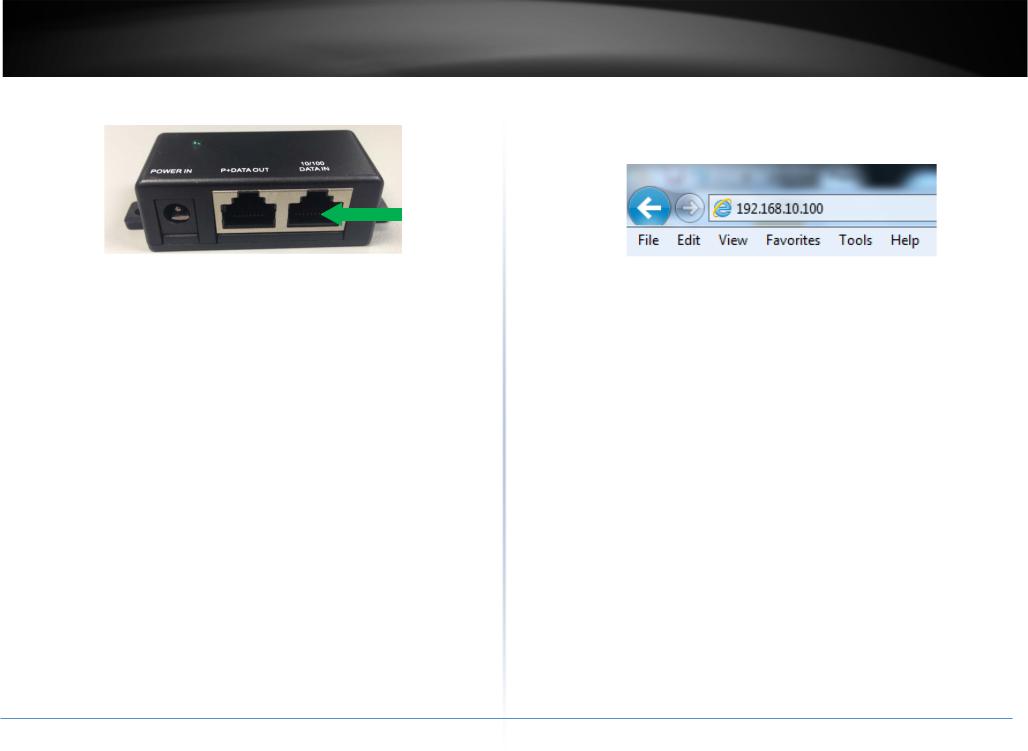
6.Using another Ethernet cable, connect one end to the DATA IN port of the injector.
7.Connect the other end of the Ethernet cable to the LAN port of your network.
8.Plug the power cord into the injector. Then connect the plug into a power outlet.
TEW-738APBO
Configuration
1.Open a web browser, type the IP address of the Access Point and then press Enter. The default IP address is 192.168.10.100.
2.Enter the Username and Password and click OK. By default the Username: root and Password: root.
3.Click the Wizard button and follow the setup wizard instructions. Click Finish to complete installation.
© Copyright 2014TRENDnet. All Rights Reserved.
8
TRENDnet User’s Guide
Applications
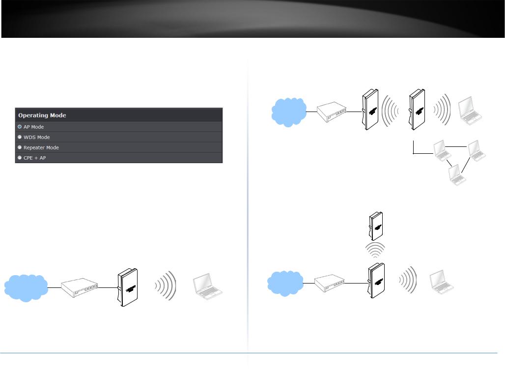
TEW-738APBO is multiple mode system which can be configured either as a wireless gateway or an access point as desired. It also can be used as a WDS link for Ethernet network expansion. This section depicts different applications on Router AP Mode, AP Mode, WDS Mode, CPE Mode, Client Bridge + Universal Repeater Mode and CPE + AP Mode.
AP Mode (including Access Point + WDS)
An access point can be either a main, relay or remote base station. A main base station is typically connected to a wired network via the Ethernet port. A relay base station relays data between main base stations and relay stations or remote base stations with clients. A remote base station is the end point to accept connections from wireless clients and pass data upwards to a network wirelessly.
Example 1: Access Point without WDS
• It can be deployed as a tradition fixed wireless Access Point
TEW-738APBO
Example 2: Access Point with WDS
•It can be deployed as a tradition fixed wireless Access Point and provides WDS link to expand network
Remote
Main
WDS
Remote
WDS
Main
© Copyright 2014TRENDnet. All Rights Reserved.
9
TRENDnet User’s Guide
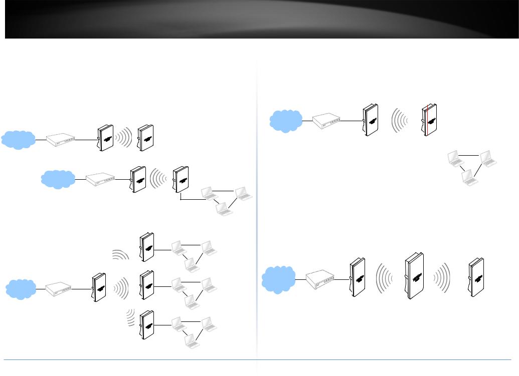
WDS Mode (Pure WDS)
An access point can be either a main, relay or remote base station. A main base station is typically connected to a wired network via the Ethernet port. A relay base station relays data between main base stations and relay stations or remote base stations with clients. A remote base station is the end point to accept connections from wireless clients and pass data upwards to a network wirelessly. In this mode, it can support single or multiple WDS links and no wireless clients can associate with it.
Example 1: Point-to-Point
WDS
Main
Example 2 : Point-to-Multi-Point
TEW-738APBO
Example 3 : Multi-Point Repeating bridge
NA
Inter
Main Base |
WIFI WAN |
LAN |
|
Station |
|||
|
|
||
|
|
|
Client Bridge + Universal Repeater Mode
It can be used as an Client Bridge + Universal Repeater to receive wireless signal over last mile applications, helping WISPs deliver wireless broadband Internet service to new residential and business customers. In this mode, TEW-738APBO is enabled with DHCP Server functions. The wired clients of TEW-738APBO are in the same subnet from Main Base Station and it accepts wireless connections from client devices.
© Copyright 2014TRENDnet. All Rights Reserved.
10
TRENDnet User’s Guide
CPE + AP Mode (Router Client + Access Point)
It can be used as an Outdoor Customer Premised Equipment (CPE) to receive wireless signal over the last mile, helping WISPs deliver wireless broadband Internet service to new residential and business customers. In this mode, theTEW-738APBO is a gateway with NAT and DHCP Server functions. The wireless and wired clients of TEW-738APBO are on the different subnet from Main Base Station and it accepts wireless connections from client devices.
TEW-738APBO
Web Management Interface Instructions
TEW-738APBO supports web-based configuration. Upon the completion of hardware installation, TEW-738APBO can be configured through a PC/NB by using its web browser such as Internet Explorer version 6.0.
•Default IP Address : 192.168.10.100
•Default IP Netmask : 255.255.255.0
•Default User Name and Password : admin/admin
Step
•IP Segment Set-up for Administrator's PC/NB: Set the IP segment of the administrator's computer to be in the same range as TEW-738APBO for accessing the system. Do not duplicate the IP Address used here with IP Address of TEW738APBO or any other device within the network
Example of Segment:
The valid range is 1 ~ 254 and 192.168.10.254 shall be avoided because it is already assigned to TEW-738APBO. 192.168.10.10 is used in the example below.
o IP Address : 192.168.10.10
oIP Netmask : 255.255.255.0
•Launch Web Browser
Launch web browser to access the web management interface of system by entering the default IP Address, http://192.168.10.100, in the URL field, and then press Enter.
• System Login: The system manager Login Page then appears.
Enter “admin” as User name and “admin” as Password, and then click OK to login to the system; the root manager account is used as an example here.
• Login Success: System Overview page will appear after successful login.
© Copyright 2014TRENDnet. All Rights Reserved.
11
TRENDnet User’s Guide
AP Mode Configuration
When AP mode is chosen, the system can be configured as an Access Point. This section provides detailed explanation for users to configure in the AP mode with help of illustrations. In the AP mode, functions listed in the table below are also available from the Web-based GUI interface.
External Network Connection Network Requirement
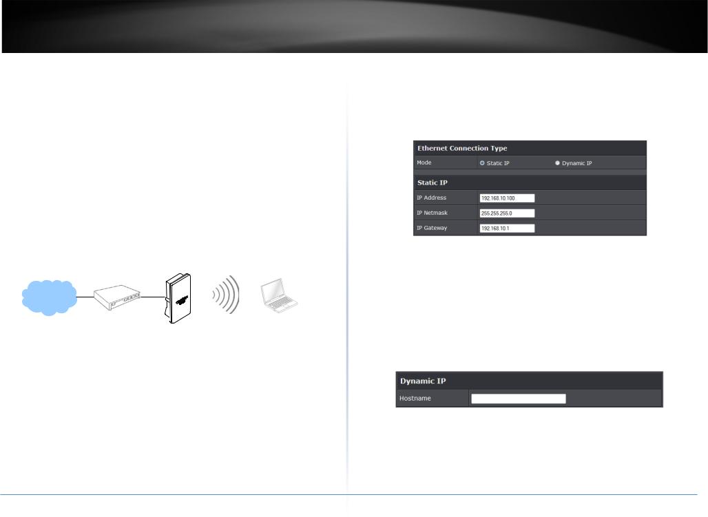
Normally, TEW-738APBO connects to a wired LAN and provides a wireless connection point to associate with wireless client as shown in Figure 3-1. Then, Wireless clients could access to LAN or Internet by associating themselves with TEW-738APBO set in AP mode.
TEW-738APBO
Configure LAN IP
Here are the instructions to setup the local IP Address and Netmask. Please click on System -> LAN and follow the below setting.
•Mode: Check either “Static IP” or “Dynamic IP” button as desired to set up the system IP of LAN port.
•Static IP: The administrator can manually setup the LAN IP address when static IP is available/ preferred.
o IP Address : The IP address of the LAN port; default IP address is 192.168.2.254
o IP Netmask : The Subnet mask of the LAN port; default Netmask is 255.255.255.0
o IP Gateway : The default gateway of the LAN port; default Gateway is 192.168.2.1
•Dynamic IP: This configuration type is applicable when the TEW-738APBO is connected to a network with the presence of a DHCP server; all related IP information will be provided by the DHCP server automatically.
o Hostname : The Hostname of the LAN port
© Copyright 2014TRENDnet. All Rights Reserved.
12
TRENDnet User’s Guide
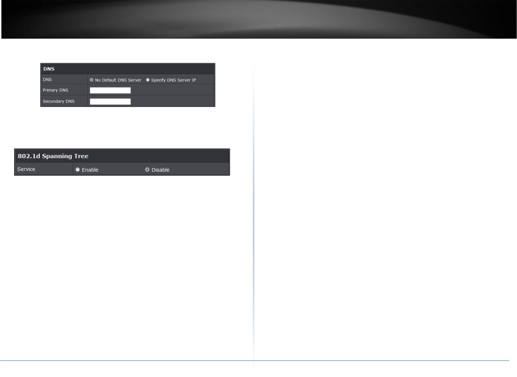
•DNS: Check either “No Default DNS Server” or “Specify DNS Server IP” button as desired to set up the system DNS.
o Primary: The IP address of the primary DNS server.
oSecondary: The IP address of the secondary DNS server.
•802.1d Spanning Tree
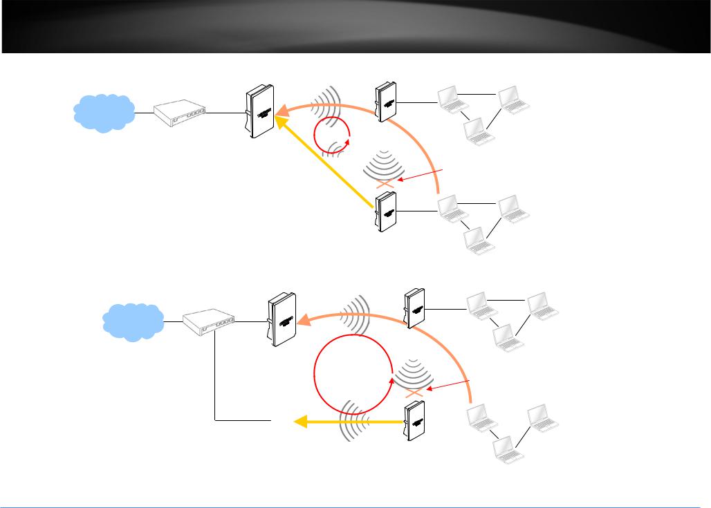
The spanning tree network protocol provides a loop free topology for a bridged LAN between LAN interface and 4 WDS interfaces from wds0 to wds3. The Spanning Tree Protocol, which is also referred to as STP, is defined in the IEEE Standard 802.1d. The Spanning tree always enabled on TEW-738APBO. Below Figures depict a loop for a bridged LAN between LAN and WDS link
Click Save button to save your changes. Click Reboot button to activate your changes
© Copyright 2014TRENDnet. All Rights Reserved.
TEW-738APBO
13
TRENDnet User’s Guide |
TEW-738APBO |
|
WDS |
Remote Base Station
LOOP |
|
|
|
WDS |
Blocked by |
|
|
|
WDS |
|
Spanning Tree Protocol |
|
|
Remote Base Station
WDS
|
Remote Base Station |
|
|
|
|
LOOP |
|
WDS |
Blocked by |
||
|
|
||||
|
|
|
Spanning Tree Protocol |
||
|
|
|
|
|
|
|
|
|
|
|
|
Base Station |
WDS |
Remote Base Station |
© Copyright 2014TRENDnet. All Rights Reserved.
14
TRENDnet User’s Guide
Wireless LAN Network
The network manager can configure related wireless settings, General Settings, Advanced Settings, Virtual AP (VAP) Setting, Security Settings and MAC Filter Settings.
Wireless General Setup
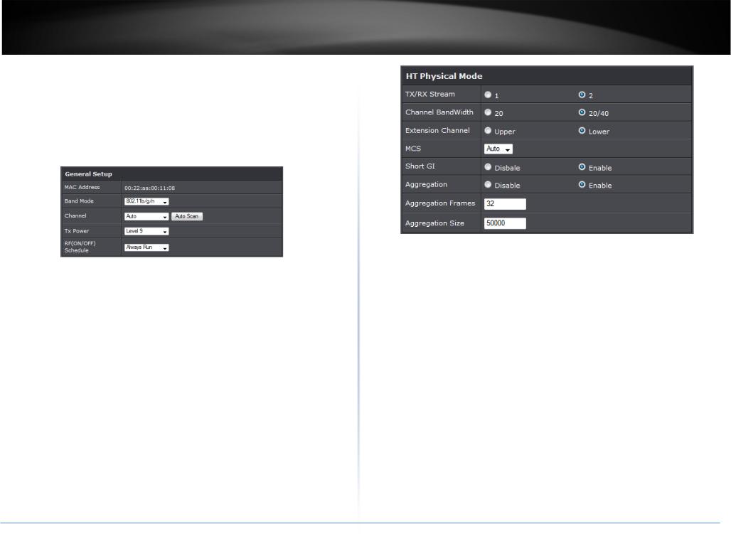
The administrator can change the data transmission, channel and output power settings for the system. Please click on Wireless -> General Setup and follow the below setting.
•MAC Address: The MAC address of the Wireless interface is displayed here.
•Band Mode: Select an appropriate wireless band; bands available are 801.11b, 802.11b/g, 802.11b/g/n or 802.11n only.
•Channel: Select the desired channel from the drop-down list to have the access point operate on. Click Auto Scan to scan for the best available channel to use based on the environment.
•Tx Power: You can adjust the output power of the system to get the appropriate coverage for your wireless network. Specify digit numbers between 1 to 100 (the unit is %) for your environment. If you are not sure which setting to choose, then keep the default setting, 100%.
•RF (ON/OFF) Schedule: Select an assigned schedule of when to have the access point turn on. Select Always Run to have the access point always on.
When Band Mode select in 802.11a only mode, the HT(High Throughput) settings should be hidden immediately.
TEW-738APBO
3
•TxStream/Rx Stream: Select the amount of transmit (TX) and Receive (RX) streams. By default, it's 2.
•Channel Bandwidth: The "20/40” MHz option is usually best. The other option is available for special circumstances.
•Extensions Channel: Select which section of channels to use for extension channels.
•MCS: This parameter represents transmission rate. By default (Auto) the fastest possible transmission rate will be selected. You have the option of selecting the speed if necessary. (Refer to Appendix C. MCS Data Rate)
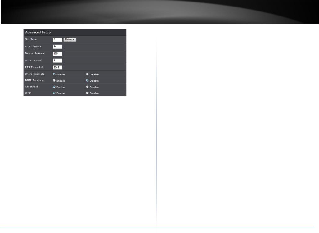
Wireless Advanced Setup
To achieve optimal wireless performance, it is necessary to tweak advance setting per requirements properly, not necessary higher the better or lower.
The administrator can change the RTS threshold and fragmentation threshold settings for the system. Please click on Wireless -> Advanced Setup and follow the below setting.
© Copyright 2014TRENDnet. All Rights Reserved.
15
|
TRENDnet User’s Guide |
|
TEW-738APBO |
|
|
|
will start to “Resend” packet before ACK is received, and throughputs become low |
|
|
|
due to excessively high re-transmission. ACK Timeout is best determined by |
|
|
|
distance between the radios, data rate of average environment. The Timeout value |
|
|
|
is calculated based on round-trip time of packet with a little tolerance, So, if |
|
|
|
experiencing re-transmissions or poor performance the ACK Timeout could be |
|
|
|
made longer to accommodate. |
|
|
• |
Beacon Interval: Beacon Interval is in the range of 20~1024 and set in unit of |
|
|
|
millisecond. The default value is 100 msec. |
|
|
|
Access Point (AP) in IEEE 802.11 will send out a special approximated 50-byte |
|
|
|
frame, called “Beacon”. Beacon is broadcast to all the stations, provides the basic |
|
|
|
information of AP such as SSID, channel, encryption keys, signal strength, time |
|
|
|
stamp, support data rate. |
|
|
|
All the radio stations received beacon recognizes the existence of such AP, and may |
|
|
|
proceed next actions if the information from AP matches the requirement. Beacon |
• |
Short Slot: By default, it’s “Enable” for reducing the slot time from the standard 20 |
|
is sent on a periodic basis, the time interval can be adjusted. |
|
By increasing the beacon interval, you can reduce the number of beacons and |
||
|
microseconds to the 9 microsecond short slot time. Slot time is the amount of time a |
|
|
|
device waits after a collision before retransmitting a packet. Reducing the slot time |
|
associated overhead, but that will likely delay the association and roaming process |
|
decreases the overall back-off, which increases throughput. Back-off, which is a |
|
because stations scanning for available access points may miss the beacons. You |
|
multiple of the slot time, is the random length of time a station waits before |
|
can decrease the beacon interval, which increases the rate of beacons. This will |
|
sending a packet on the LAN. For a sender and receiver own right of the channel the |
|
make the association and roaming process very responsive; however, the network |
|
shorter slot time help manage shorter wait time to re-transmit from collision |
|
will incur additional overhead and throughput will go down. |
|
because of hidden wireless clients or other causes. When collision sources can be |
• |
DTIM Interval: The DTIM interval is in the range of 1~255. The default is 1. |
|
removed sooner and other senders attempting to send are listening the channel |
|
DTIM is defined as Delivery Traffic Indication Message. It is used to notify the |
|
(CSMA/CA) the owner of the channel should continue ownership and finish their |
|
wireless stations, which support power saving mode, when to wake up to receive |
|
transmission and release the channel. Then, following ownership of the channel will |
|
multicast frame. DTIM is necessary and critical in wireless environment as a |
|
be sooner for the new pair due to shorter slot time. However, when long duration of |
|
mechanism to fulfill power-saving synchronization. A DTIM interval is a count of the |
|
existing collision sources and shorter slot time exist the owners might experience |
|
number of beacon frames that must occur before the access point sends the |
|
subsequent collisions. When adjustment to longer slot time can’t improve |
|
buffered multicast frames. For instance, if DTIM Interval is set to 3, then the Wi-Fi |
|
performance then RTS/CTS could supplement and help improve performance. |
|
clients will expect to receive a multicast frame after receiving three Beacon frame. |
• |
ACK Timeout: ACK timeout is in the range of 1~255 and set in unit of microsecond. |
|
The higher DTIM interval will help power saving and possibly decrease wireless |
|
The default value is 32 microsecond. All data transmission in 802.11b/g request an |
|
throughput in multicast applications. |
|
“Acknowledgement” (ACK) send by receiving radio. The transmitter will resend the |
• |
RTS Threshold: TRTS Threshold is in the range of 1~2347 byte. The default is 2347 |
|
original packet if correspondent ACK failed to arrive within specific time interval, |
||
|
|
byte. The main purpose of enabling RTS by changing RTS threshold is to reduce |
|
|
also refer to as “ACK Timeout”. |
|
|
|
|
possible collisions due to hidden wireless clients. RTS in AP will be enabled |
|
|
ACK Timeout is adjustable due to the fact that distance between two radio links |
|
|
|
|
automatically if the packet size is larger than the Threshold value. By default, RTS is |
|
|
may vary in different deployment. ACK Timeout makes significant influence in |
|
disabled in a normal environment supports non-jumbo frames. |
|
performance of long distance radio link. If ACK Timeout is set too short, transmitter |
• |
Short Preamble: By default, it’s “Enable”. To Disable is to use Long 128-bit Preamble |
© Copyright 2014TRENDnet. All Rights Reserved.
16
TRENDnet User’s Guide |
TEW-738APBO |
Synchronization field. The preamble is used to signal "here is a train of data coming" to the receiver. The short preamble provides 72-bit Synchronization field to improve WLAN transmission efficiency with less overhead.
• WMM: By default, it's “Enabled”.
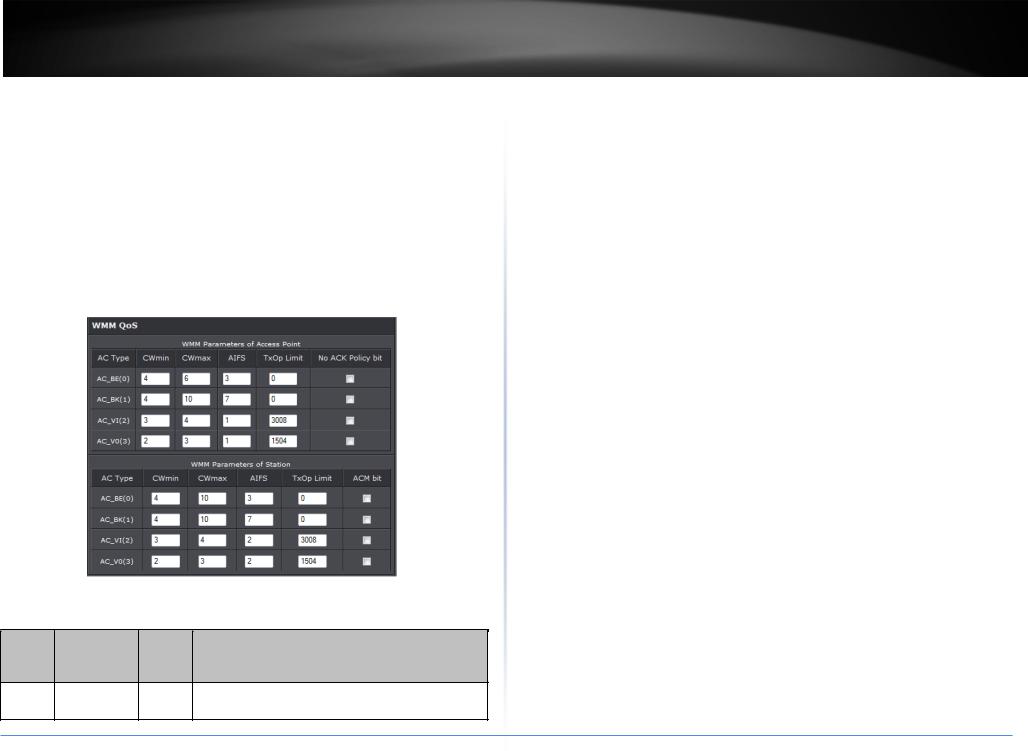
Wireless WMM QoS Setup
To achieve optimal wireless performance, it is necessary to tweak advance setting per requirements properly, not necessary higher the better or lower.
The administrator can change the RTS threshold and fragmentation threshold settings for the system. Please click on Wireless -> Advanced
•WMM Parameters of Access Point : This affects traffic flowing from the access point to the client station
|
Data |
|
|
|
Queue |
Transmitted |
Priority |
Description |
|
|
AP to Clients |
|
|
|
AC_BK |
Background. |
Low |
High throughput. Bulk data that requires maximum |
|
throughput and is not time-sensitive is sent to this |
||||
|
|
|
|
|
|
queue (FTP data, for example). |
|
|
|
|
|
|
AC_BE |
Best Effort |
Medium |
Medium throughput and delay. Most traditional IP |
|
data is sent to this queue |
||||
AC_VI |
Video |
High |
Minimum delay. Time-sensitive video data is |
|
automatically sent to this queue |
||||
|
|
|
||
AC_VO |
Voice |
High |
Time-sensitive data like VoIP and streaming media |
|
are automatically sent to this queue |
||||
|
|
|
Configuring QoS options consists of setting parameters on existing queues for different types of wireless traffic. You can configure different minimum and maximum wait times for the transmission of packets in each queue based on the requirements of the media being sent. Queues automatically provide minimum transmission delay for Voice, Video, multimedia, and mission critical applications, and rely on best-effort parameters for traditional IP data.
As an Example, time-sensitive Voice & Video, and multimedia are given effectively higher priority for transmission (lower wait times for channel access), while other applications and traditional IP data which are less time-sensitive but often more dataintensive are expected to tolerate longer wait times.
o Aifsn: The Arbitration Inter-Frame Spacing Number specifies a wait time (in milliseconds) for data frames
oCWmin: Minimum Contention Window. This parameter is input to the algorithm that determines the initial random back-off wait time ("window") for retry of a transmission. The value specified here in the Minimum Contention Window is the upper limit (in milliseconds) of a range from which the initial random back-off
wait time is determined.
oCWmax: Maximum Contention Window. The value specified here in the Maximum Contention Window is the upper limit (in milliseconds) for the doubling of the random back-off value. This doubling continues until either the data frame is sent or the Maximum Contention Window size is reached. Once the Maximum Contention Window size is reached, retries will continue until a maximum number of retries allowed is reached. Valid values for the "cwmax" are 1, 3, 7, 15, 31, 63, 127, 255, 511, or 1024. The value for "cwmax" must be higher than the value for
"cwmin".
oTxop: Transmission Opportunity is an interval of time when a WME AP has the right to initiate transmissions onto the wireless medium (WM). This value specifies (in milliseconds) the Transmission Opportunity (TXOP) for AP; that is, the
© Copyright 2014TRENDnet. All Rights Reserved.
17

TRENDnet User’s Guide |
TEW-738APBO |
interval of time when the WMM AP has the right to initiate transmissions on the |
milliseconds) for data frames |
||||
wireless network. |
|
|
o CWmin: Minimum Contention Window. This parameter is input to the |
||
o ACM: Admission Control Mandatory, ACM only takes effect on AC_VI and AC_VO. |
algorithm that determines the initial random backoff wait time ("window") |
||||
When you do not click Checkbox, it means that the ACM is controlled by the |
for retry of a transmission. The value specified here in the Minimum |
||||
connecting AP. If you click Checkbox, it means that the Client is in charge. |
Contention Window is the upper limit (in milliseconds) of a range from |
||||
o AckPolicy: Acknowledgment Policy, WMM defines two ACK policies: Normal ACK |
which the initial random backoff wait time is determined. |
||||
o CWmax: Maximum Contention Window. The value specified here in the |
|||||
and No ACK. Click “Checkbox” indicates “No ACK” |
|||||
|
|
|
|
Maximum Contention Window is the upper limit (in milliseconds) for the doubling |
|
|
Data |
|
|
of the random backoff value. This doubling continues until either the data frame |
|
Queue |
Transmitted |
Priority |
Description |
is sent or the Maximum Contention Window size is reached. Once the Maximum |
|
|
Clients to AP |
|
|
Contention Window size is reached, retries will continue until a maximum number |
|
|
|
|
High throughput. Bulk data that |
of retries allowed is reached. Valid values for the "cwmax" are 1, 3, 7, 15, 31, 63, |
|
|
|
|
127, 255, 511, or 1024. The value for "cwmax" must be higher than the value for |
||
|
|
|
requires maximum |
||
|
|
|
"cwmin". |
||
AC_BK |
Background. |
Low |
throughput and is not time- |
||
o Txop: Transmission Opportunity is an interval of time when a WME AP has the |
|||||
|
|
|
sensitive is sent to this queue |
||
|
|
|
(FTP data, for example). |
right to initiate transmissions onto the wireless medium (WM). This value |
|
|
|
|
specifies (in milliseconds) the Transmission Opportunity (Txop) for AP; that is, the |
||
|
|
|
Medium throughput and delay. |
||
|
|
|
interval of time when the WMM AP has the right to initiate transmissions on the |
||
AC_BE |
Best Effort |
Medium |
Most traditional IP data is |
||
wireless network. |
|||||
|
|
|
sent to this queue |
||
|
|
|
o ACM: Admission Control Mandatory, ACM only takes effect on AC_VI and AC_VO. |
||
|
|
|
Minimum delay. Time-sensitive |
||
|
|
|
When you do not click Checkbox, it means that the ACM is controlled by the |
||
AC_VI |
Video |
High |
video data is automatically |
connecting AP. If you click Checkbox, it means that the Client is in charge. |
|
|
|
|
sent to this queue |
Click Save button to save your changes. Click Reboot button to activate your changes. |
|
|
|
|
Time-sensitive data like VoIP |
The items in this page are for AP's RF advanced settings and will be applied to all VAPs |
|
AC_VO |
Voice |
High |
and streaming media are |
and WDS Links. |
|
automatically sent to this |
|
||||
|
|
|
|
||
|
|
|
queue |
|
|
When the no acknowledgment (No ACK) policy is used, the recipient does not acknowledge received packets during wireless packet exchange. This policy is suitable in the environment where communication quality is fine and interference is weak. While the No ACK policy helps improve transmission efficiency, it can cause increased packet loss when communication quality deteriorates. This is because when this policy is used, a sender does not retransmit packets that have not been received by the recipient. When the Normal ACK policy is used, the recipient acknowledges each received unicast packet.
• WMM Parameters of Station: This affects traffic flowing from the client station to the access point.
oAifsn: The Arbitration Inter-Frame Spacing Number specifies a wait time (in
©Copyright 2014TRENDnet. All Rights Reserved.
18
TRENDnet User’s Guide
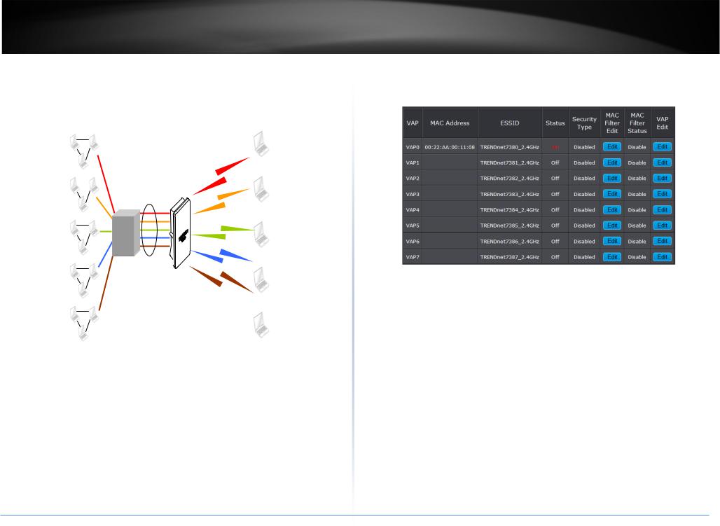
Create Virtual AP (VAP)
The TEW-738APBO support broadcasting multiple SSIDs, allowing the creation of Virtual Access Points, partitioning a single physical access point into 7 logical access points, each of which can have a different set of security, VLAN Tag(ID) and network settings. Figure 3-2 shows multiple SSIDs with different security type and VLAN settings.
Sales Network |
VLA |
SSID 1 |
|
|
|
||
|
N #1 |
W |
|
|
|
|
|
|
|
|
E |
|
|
|
|
Engineer Network |
WPA- |
SSID 2 |
|
VLA |
|
||
N #2 |
PSK/TKIP |
|
|
Market Network |
WPA- |
SSID 3 |
|
PSK/AES |
|||
VLA |
WPA2- |
|
|
N #3 |
|
||
PSK/TKIP |
|
||
|
|
||
Guest Network |
WPA2- |
SSID 4 |
|
VLA |
|||
|
|||
N #4 |
PSK/AES |
|
|
|
|
||
Accounting Network |
|
SSID 5 |
|
VLA |
|
N #5
Multiple SSIDs with different Security Type and VLAN Tag
TEW-738APBO
Virtual AP Overview
The administrator can view all of the Virtual AP's settings via this page.
Please click on Wireless -> Virtual AP Setup and the Virtual AP Overview Page appears.
•VAP: Indicate the system's Virtual AP.
•MAC Address: The MAC address of the VAP Interface is displayed here. When you enable AP and reboot system, the MAC address will display here.
•ESSID: Indicate the ESSID of the respective Virtual AP
•Status: Indicate the Status of the respective Virtual AP. The Primary AP always on.
•Security Type: Indicate a used security type of the respective Virtual AP.
•MAC Filter: Indicate a used MAC filter of the respective Virtual AP.
•Edit: Click Edit button to configure Virtual AP's settings, including security type and MAC Filter.
© Copyright 2014TRENDnet. All Rights Reserved.
19

TRENDnet User’s Guide |
TEW-738APBO |
Virtual AP Setup |
are Disable, WEP, WPA-PSK, WPA2-PSK, WPA-Enterprise, WPA2-Enterprise and |
For each Virtual AP, administrators can configure SSID, VLAN tag(ID), SSID broadcasting, |
WEP 802.1X. |
o Disable: Data are unencrypted during transmission when this option is selected. |
|
Maximum number of client associations, security type settings. |
|
Click Edit button on the Edit column, and then a Virtual AP setup page appears. |
|
|
• WEP Auth Method: Enable the desire option among OPEN or SHARED |
|
• ESSID: Extended Service Set ID, when clients are browsing for available wireless |
o Key Index: Key index is used to designate the WEP key during data transmission. 4 |
|
networks, this is the SSID that will appear in the list. ESSID will determine the |
different WEP keys can be entered at the same time, but only one is chosen. |
|
service type available to AP's clients associated with the specified VAP. |
o WEP Key #: Enter HEX or ASCII format WEP key value; the system supports up to 4 |
|
• Hidden SSID: By default, it’s “Disable”. Enable this option to stop the SSID broadcast |
sets of WEP keys. |
|
in your network. When disabled, people could easily obtain the SSID information |
• WPA-PSK (or WPA2-PSK) : WPA (or WPA2) Algorithms, allows the system accessing |
|
with the site survey software and get access to the network if security is not turned |
||
on. When enabled, network security is enhanced. It’s suggested to enable it after AP |
the network by using the WPA-PSK protected access. |
|
security settings are archived and setting of AP clients could make to associate to it. |
|
|
• Client Isolation: Select Enable, all clients will be isolated from each other, that mean |
|
|
all clients cannot reach to other clients. Below Figures depict Client Isolation and AP |
|
|
Isolation |
|
|
• IAPP: |
|
|
• Maximum Clients: The default value is 32. You can enter the number of wireless |
|
|
clients that can associate to a particular SSID. When the number of client is set to 5, |
|
|
only 5 clients at most are allowed to connect to this VAP. |
|
|
• VLAN Tag (ID) : By default, it’s selected “Disable”. |
|
|
This system supports tagged Virtual LAN (VLAN). A valid number of 1 to 4094 can be |
|
|
entered after it’s enabled. If your network utilize VLANs you could tie a VLAN Tag to |
|
|
a specific SSID, and packets from/to wireless clients belonging to that SSID will be |
o Cipher Suite: By default, it is AES. Select either AES or TKIP cipher suites |
|
tagged with that VLAN Tag. This enables security of wireless applications by |
||
o Group Key Update Period: By default, it is 600 seconds. This time interval for |
||
applying VLAN Tag. |
||
rekeying GTK, broadcast/multicast encryption keys, in seconds. Entering the time- |
||
• Security Type: Select the desired security type from the drop-down list; the options |
||
length is required. |
||
|
|
|
© Copyright 2014TRENDnet. All Rights Reserved. |
|
|
|
20 |
TRENDnet User’s Guide |
TEW-738APBO |
|
o Master Key Update Period: By default, it is 83499 seconds. This time interval for |
• Radius Server Settings : |
|
rekeying GTK, broadcast/multicast encryption keys, in seconds. Entering the time- |
o IP Address: Enter the IP address of the Authentication RADIUS server. |
|
length is required. |
o Port: By default, it’s 1812. The port number used to communicate with RADIUS |
|
o Pre-shared Key: Enter the pre-shared key; the format shall go with the selected |
server. |
|
key type. |
o Shared secret: A secret key used between system and RADIUS server. Supports 8 |
|
|
to 64 characters. |
|
• WPA-Enterprise (or WPA2-Enterprise): The RADIUS authentication and encryption |
o Accounting RADIUS Server: Enable to set Account RADIUS server. |
|
• WEP 802.1X: When WEP 802.1x Authentication is enabled, please refer to the |
||
will be both enabled if this is selected. |
||
|
following Dynamic WEP and RADIUS settings to complete configuration. |
• WPA General Settings: |
• |
Radius Server Settings: |
||
|
o IP Address: Enter the IP address of the Authentication RADIUS server. |
|||
o Cipher Suite: By default, it is AES. Select either AES or TKIP cipher suites |
|
|||
|
o Port: By default, it’s 1812. The port number used to communicate with RADIUS |
|||
o Group Key Update Period: By default, it’s 3600 seconds. This time interval for |
|
|||
|
server. |
|||
rekeying GTK, broadcast/multicast encryption keys, in seconds. Entering the time- |
|
|||
|
o Shared secret: A secret key used between system and RADIUS server. Supports 8 |
|||
length is required. |
|
|
||
o Master Key Update Period: By default, it is 83499 seconds. This time interval for |
|
to 64 characters. |
||
|
o Accounting RADIUS Server: Enable to set Account RADIUS server. |
|||
rekeying GTK, broadcast/multicast encryption keys, in seconds. Entering the time- |
|
|||
length is required. |
|
Click Save button to save your changes. Click Reboot button to activate your changes |
||
o EAP Reauth Period: |
By default, it's 3600 seconds. Set WPA2 PMKID cache |
|||
|
|
|||
timeout period, after time out, the cached key will be deleted.
oPre-Authentication: By default, it's “Disable”. To Enable is use to speed up roaming before pre-authenticating IEEE 802.1X/EAP part of the full RSN authentication and key handshake before actually associating with a new AP.
©Copyright 2014TRENDnet. All Rights Reserved.
21
TRENDnet User’s Guide |
TEW-738APBO |
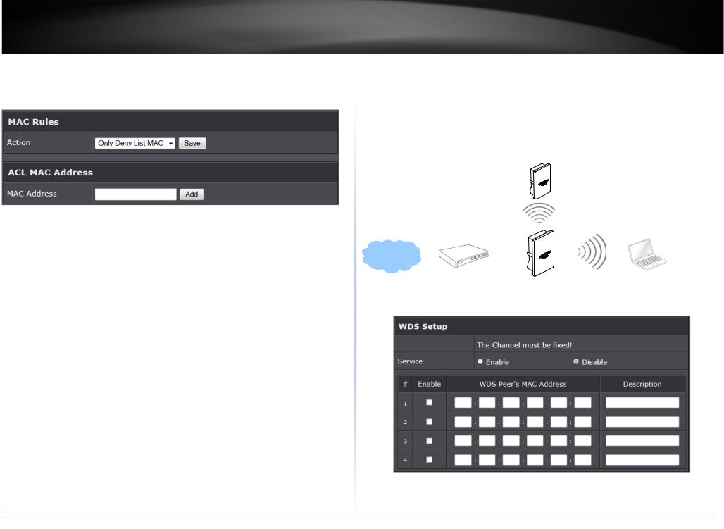
Wireless MAC Filter Setup |
Wireless Network Expansion |
Continue Virtual AP Setup section. For each Virtual AP setting, the administrator can allow or reject clients to access each Virtual AP.
The administrator could create WDS Links to expand wireless network. When WDS is enabled, access point functions as a wireless bridge and is able to communicate with other access points via WDS links. A WDS link is bidirectional and both side must support WDS. Access points know each other by MAC Address. In other words, each access point needs to include MAC address of its peer. Ensure all access points are configured with the same channel and own same security type settings.
Remote Bass Station
•MAC Filter Setup: By default, it’s “Disable”. Options are Disable, Only Deny List MAC or Only Allow List MAC.
Two ways to set MAC filter rules:
o Only Allow List MAC: The wireless clients in the “Enable” list will be allowed to access the Access Point; All others or clients in the “Disable” list will be denied.
o Only Deny List MAC: The wireless clients in the “Enable” list will be denied to access the Access Point; All others or clients in the “Disable” list will be allowed.
Add a station MAC: Enter MAC address (e.g. aa:bb:cc:00:00:0a) and click “Add” button, then the MAC address should display in the “Enable” List.
There are a maximum of 20 clients allowed in this “Enable” List. The MAC addresses of the wireless clients can be added and removed to the list using the Add and Remove buttons. Click Reboot button to activate your changes
WDS
SSID:
Please click on Wireless -> WDS Setup and follow the below setting.
• Security Type: Option is “Disable”, “WEP”, “TKIP”or “AES” from drop-down list. Needs the same type to build WDS links. Security type takes effect when WDS is
© Copyright 2014TRENDnet. All Rights Reserved.
22
TRENDnet User’s Guide |
TEW-738APBO |
enabled. |
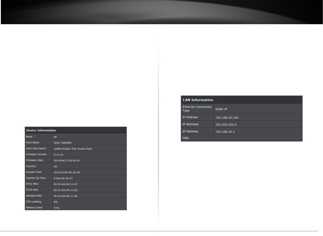
o Host Description: A description of the system. |
o WEP Key: Enter 5 / 13 ASCII or 10 / 26 HEX format WEP key. |
o Firmware Version: The current installed firmware version. |
o TKIP Key: Enter 8 to 63 ASCII or 64 HEX format TKIP key. |
o Firmware Date: The build time of installed firmware. |
o AES Key: Enter 8 to 63 ASCII or 64 HEX format AES key. |
o Device Time: The current time of the system. |
• WDS MAC List |
o System Up Time: The time period that system has been in service since last |
o Enable: Click Enable to create WDS link. |
reboot. |
o WDS Peer's MAC Address: Enter the MAC address of WDS peer. |
o ETH1/ETH2MAC: Ethernet MAC address of the access point. |
o Description: Description of WDS link. |
o Wireless MAC: Wireless MAC address of the access point |
Click Save button to save your changes. Click Reboot button to activate your changes |
o CPU Loading: The CPU loading of the access point |
|
o Memory Used: Memory usage of the access point. |
System Status |
• LAN Information: Display total received and transmitted statistics on the LAN |
This section breaks down into subsections of System Overview, Associated Clients |
interface. |
Status, WDS Link Status, Extra Information and Event Log. |
|
System Overview |
|
Display detailed information of System, Network, LAN and Wireless in the System |
|
Overview page. |
|
• Device Information: Display the information of the system. |
|
o Ethernet Connection Type: The connection applied on the access point. o IP Address: The management IP of system. By default, it’s 192.168.2.254. o IP Netmask: The network mask. By default, it’s 255.255.255.0.
o IP Gateway: The gateway IP addresses and by default, it’s 192.168.2.1. o Primary DNS: The primary DNS server in service.
o Operating Mode: The mode currently in service.
oHost Name: The name of the system.
©Copyright 2014TRENDnet. All Rights Reserved.
23

TRENDnet User’s Guide |
TEW-738APBO |
• Wireless Information: Display total received and transmitted statistics on available |
Enterprise. |
Virtual AP. |
o Clients: Display total number of wireless connections for each VAP. |
|
• VAP Clients: Display all associated clients on each Virtual AP. |
o WiFi: Wireless status of the access point. |
o MAC Address: MAC address of associated clients |
|
o RSSI: Signal Strength of from associated clients. |
||
o Band: Operating wireless band of the access point. |
||
o TX/RX Rate: Transmit and receive connection rate |
||
o Channel: Operating channel of the access point. |
||
o TX/RX SEQ: Transmit and receive sequence. |
||
o Current Tx Power: Transmit power of the access point. |
||
o TX/RX Bytes: Transmit and receive bytes |
||
o Data Rate: Current wireless data rate of the access point. |
||
o Connect Time: Connection time |
||
|
||
Associated Clients Status |
o Disconnect: Click “Disconnect” button to manually disconnect a wireless client in |
|
a Virtual AP. |
||
It displays ESSID, on/off Status, Security Type, total number of wireless clients associated |
Show WDS Link Status |
|
with all Virtual AP. |
||
|
Peers MAC Address, antenna 0/1 received signal strength, phy mode and channel |
|
|
bandwidth for each WDS are available. |
o MAC Address: Display MAC address of WDS peer.
o RSSI: Indicate the signal strength of the respective WDS links. o TX/RX SEQ: Transmit and receive sequence.
o TX/RX Bytes: Transmit and receive bytes
• VAP Information: Highlights key VAP information. o VAP: Available VAP from Primary AP to VAP6.
o ESSID: Display name of ESSID for each VAP. o Status : On/Off
oSecurity Type: Display chosen security type; WEP, WPA/WPA2-PSK, WPA/WPA2-
©Copyright 2014TRENDnet. All Rights Reserved.
24
Loading...