


 Loading...
TRENDnet User’s Guide |
|
Contents |
|
PRODUCT OVERVIEW ....................................................................................................... |
2 |
FEATURES............................................................................................................................................ |
2 |
FRONT VIEW....................................................................................................................................... |
3 |
LED INDICATORS............................................................................................................................... |
3 |
REAR VIEW ......................................................................................................................................... |
5 |
PACKAGE CONTENTS......................................................................................................................... |
5 |
SWITCH INSTALLATION................................................................................................... |
5 |
DESKTOP HARDWARE INSTALLATION............................................................................................ |
5 |
RACK MOUNT HARDWARE INSTALLATION.................................................................................... |
6 |
BASIC INSTALLATION ........................................................................................................................ |
6 |
CONNECT ADDITIONAL DEVICES TO YOUR SWITCH....................................................................... |
8 |
CONFIGURE YOUR SWITCH............................................................................................. |
9 |
ACCESS YOUR SWITCH MANAGEMENT PAGE .................................................................................. |
9 |
SWITCH INFO ...................................................................................................................................... |
9 |
SYSTEM............................................................................................................................................. |
11 |
PHYSICAL INTERFACE..................................................................................................................... |
22 |
BRIDGE.............................................................................................................................................. |
26 |
SNMP............................................................................................................................................... |
56 |
ACCESS CONTROL CONFIG............................................................................................................. |
63 |
RMON.............................................................................................................................................. |
69 |
VOICE VLAN ................................................................................................................................... |
75 |
SECURITY.......................................................................................................................................... |
79 |
DESTINATION MAC FILTER.......................................................................................................... |
84 |
DHCP SNOOPING............................................................................................................................ |
86 |
LLDP (LINK-LAYER DISCOVERY PROTOCOL)........................................................................... |
90 |
STATISTIC......................................................................................................................................... |
93 |
SWITCH MAINTENANCE................................................................................................................. |
94 |
SAVE SETTINGS TO FLASH.......................................................................................................... |
101 |
WEB SMART SWITCH MANAGEMENT UTILITY.................................................. |
102 |
SYSTEM REQUIREMENTS ............................................................................................................ |
102 |
|
TEG-082WS |
INSTALLATION............................................................................................................................... |
102 |
USING THE UTILITY...................................................................................................................... |
103 |
DISCOVERY LIST............................................................................................................................ |
104 |
DEVICE SETTING........................................................................................................................... |
105 |
MAIN MENU OPTIONS ................................................................................................................. |
106 |
TECHNICAL SPECIFICATIONS ................................................................................... |
108 |
TROUBLESHOOTING.................................................................................................... |
110 |
APPENDIX........................................................................................................................ |
111 |
HOW TO FIND YOUR IP ADDRESS? ............................................................................................. |
111 |
HOW TO FIND YOUR MAC ADDRESS?........................................................................................ |
118 |
REGULATIONS................................................................................................................ |
119 |
FEDERAL COMMUNICATION COMMISSION INTERFERENCE STATEMENT.................................. |
119 |
ROHS.............................................................................................................................................. |
119 |
EUROPE – EU DECLARATION OF CONFORMITY....................................................................... |
120 |
LIMITED WARRANTY .................................................................................................. |
121 |
© Copyright 2014 TRENDnet. All Rights Reserved. |
1 |
TRENDnet User’s Guide
Product Overview
TEG-082WS
Features
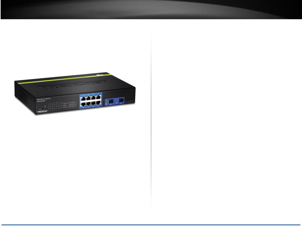
TRENDnet’s fanless 8-Port Gigabit Web Smart Switch, model TEG-082WS, offers 8 x Gigabit ports, 2 x shared SFP slots, a built-in power supply, and a 16 Gbps switching capacity. This IPv6 ready switch offers advanced traffic management, troubleshooting, access control, energy saving GREENnet, and monitoring features at a reduced cost.
TEG-082WS
Hardware Design
Provides 8 x Gigabit ports, 2 x shared SFP slots, a 16 Gbps switching capacity, a built-in power supply, and rackmount brackets
Fanless
Fanless design reduces energy consumption and operating noise
IPv6 Ready
This switch supports IPv6 configuration and IPv6 neighbor discovery
Traffic Management
A broad range of network configurations are supported by: 802.3ad link aggregation, Asymmetric VLAN, 802.1Q VLAN, Voice VLAN, Private VLAN, Bandwidth Controls, GVRP, IGMP v1-v3, 802.1p Class of Service (CoS), Spanning Tree (STP, RSTP, and MSTP), and QoS queue scheduling
Troubleshooting
Real time traffic comparison charts, error group charts, and a convenient cable diagnostic test aid in rapid troubleshooting
Access Controls
Features such as ACL, SSL, MAC/port filtering, Denial of Service controls, 802.1X, TACACS+, and RADIUS are compatible with layered network access controls
Monitoring
RMON, SNMP, SNMP Trap, and Port Mirroring support administrator monitoring solutions
© Copyright 2014 TRENDnet. All Rights Reserved. |
2 |
TRENDnet User’s Guide |
TEG-082WS |
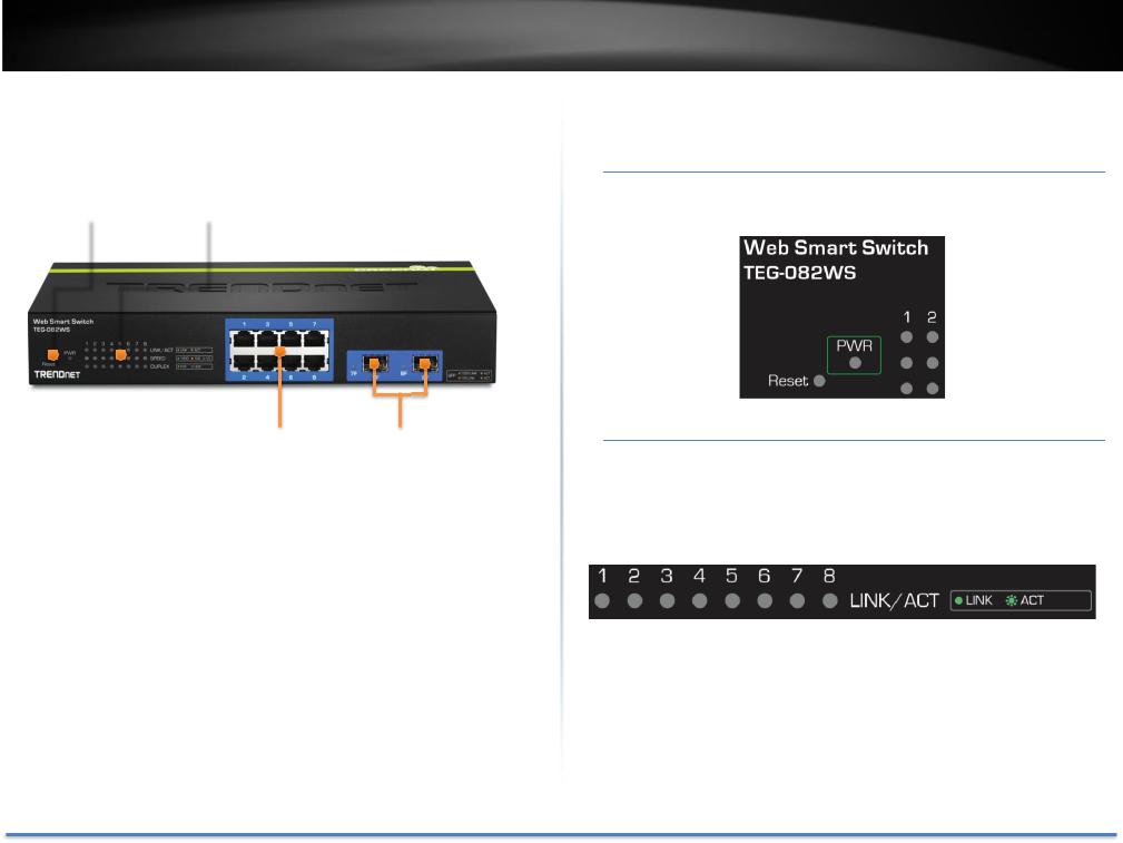
Front View
Reset Button |
LED Indicators |
||||
|
|
|
|
|
|
|
|
|
|
|
|
LED Indicators
Power (PWR) LED
On |
The TEG-082WS is powered on. |
Off |
The TEG-082WS is not powered. |
GbE Network Ports |
SFP Share Port |
Interfaces
Reset Button |
Press and hold this button for 10 seconds and |
|
release to reset the switch to factory defaults. |
Gigabit Ethernet |
Connect network devices and can be used for uplink |
Ports (1-8) |
or downlink connections. Ports 7 and 8 are shared |
|
with SFP slots 7F and 8F and will be disabled when |
|
SFP slots (7F, 8F) are in use. |
SFP slots (7F, 8F) |
Supports optional 100 or 1000BASE-SX/LX mini-GBIC |
|
modules. |
Link/ACT LED (per port)
On |
The respective port is successfully connected to an Ethernet |
|
network. |
Blinking |
The port is transmitting or receiving data on the Ethernet |
|
network. |
Off |
No link. |
© Copyright 2014 TRENDnet. All Rights Reserved. |
3 |
TRENDnet User’s Guide
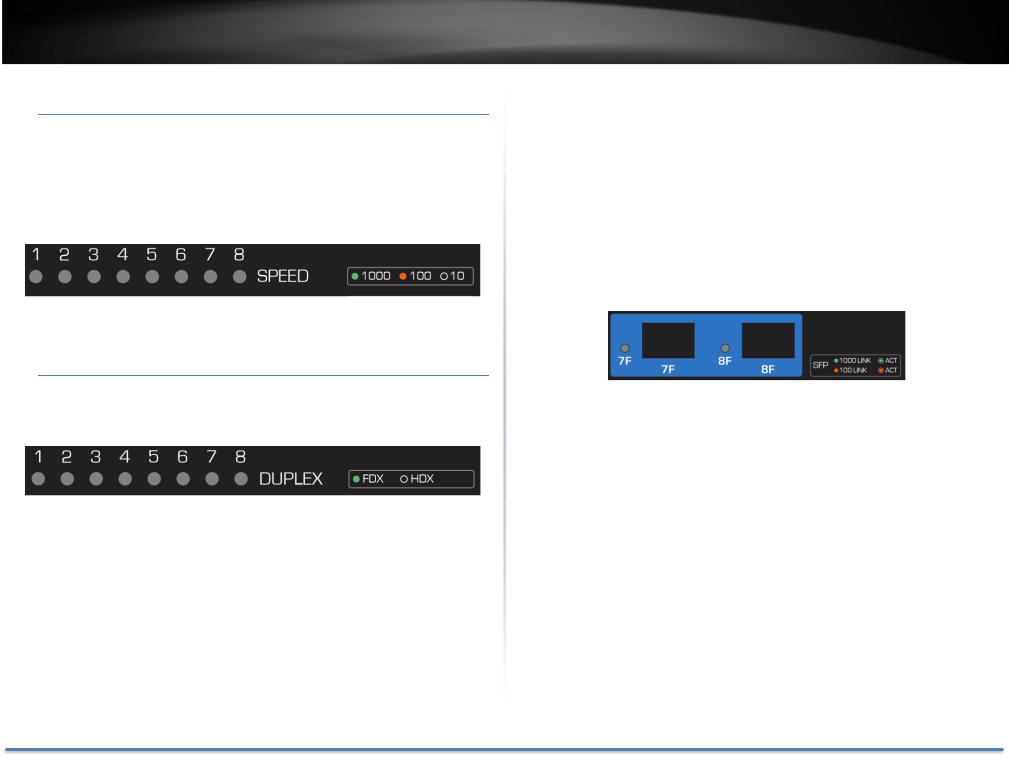
Speed LED (per port)
Green |
When respective LED shows in solid green LED, the port is |
|
connected to a 1000Mbps Gigabit Ethernet network. |
Amber |
When respective LED shows in solid amber, the port is |
|
connected to a 100Mbps Ethernet network. |
Off |
When the LINK LED is on and Speed LED is off, the respective |
|
port is connected to a 10Mbps Ethernet network. |
Duplex (per port)
On |
Full duplex Ethernet |
Off |
Half duplex Ethernet |
|
|
TEG-082WS |
Shared SFP Slots (7F, 8F) |
||
|
|
|
|
Solid |
The port is inserted mini-GBIC Gigabit module and gigabit link |
|
Green |
is established. |
|
Blink in |
Traffic is passing through this SPF port with gigabit link. |
|
Green |
|
|
Solid |
The port is inserted mini-GBIC 100Mbps module and 100M |
|
Amber |
link is established. |
|
Blink in |
Traffic is passing through this SPF port with 100Mbps link. |
|
Amber |
|
|
Off |
No link |
© Copyright 2014 TRENDnet. All Rights Reserved. |
4 |
TRENDnet User’s Guide
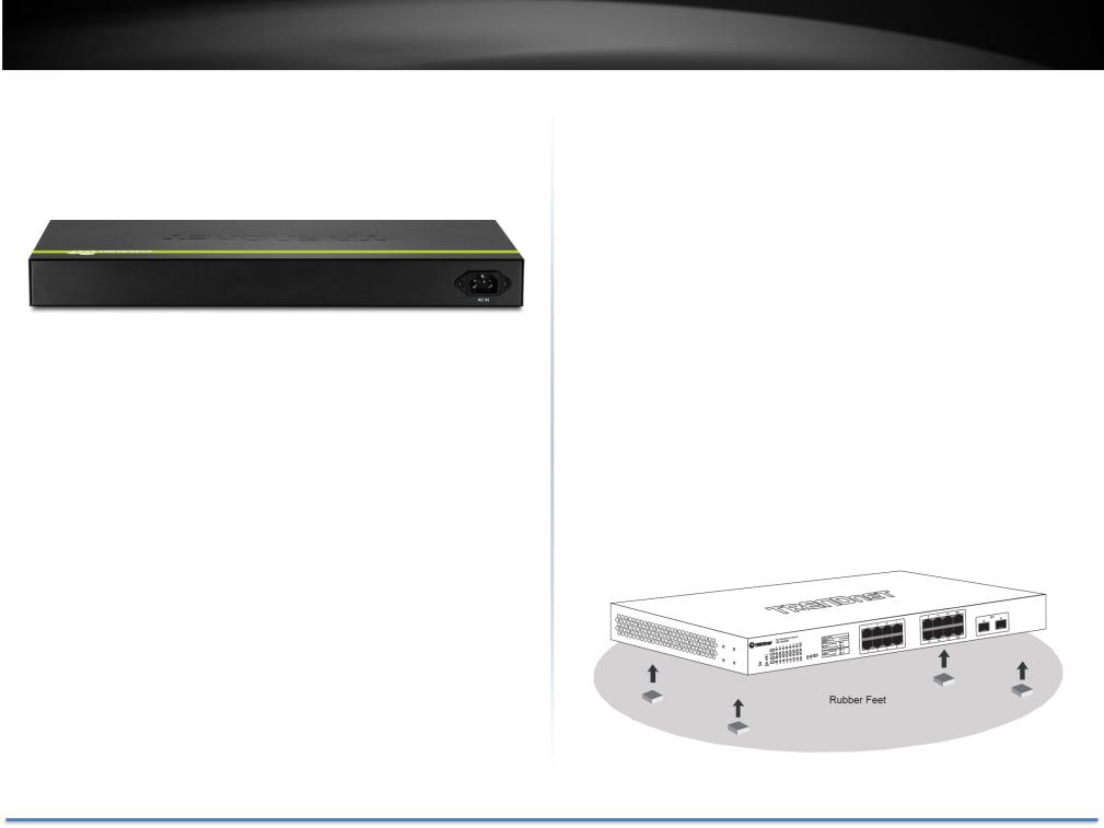
Rear View
AC Power Connector – Connect the AC power cord to the connector and the other side into a power outlet. (Input: 100~240VAC, 50/60Hz)
Package Contents
TEG-082WS package includes:
•TEG-082WS
•Multi-Language Quick Installation Guide
•CD-ROM (Utility and User’s Guide)
•Power cord (1.8 m / 6 ft.)
•Rack mount hardware
If any package content is missing or damaged, please contact the retail store, online retailer, or reseller/distributor from which the product was purchased.
TEG-082WS
Switch Installation
Desktop Hardware Installation
The site where you install the switch stack may greatly affect its performance. When installing, consider the following pointers:
Note: The model showing in illustrations may be different to the one you have.
Install the Switch in a fairly cool and dry place.
Install the Switch in a site free from strong electromagnetic field generators (such as motors), vibration, dust, and direct exposure to sunlight.
Leave at least 10cm of space at the front and rear of the hub for ventilation.
Install the Switch on a sturdy, level surface that can support its weight, or in an EIA standard-size equipment rack. For information on rack installation, see the next section, Rack Mounting.
When installing the Switch on a level surface, attach the rubber feet to the bottom of each device. The rubber feet cushion the hub and protect the hub case from scratching.
© Copyright 2014 TRENDnet. All Rights Reserved. |
5 |
TRENDnet User’s Guide
Rack Mount Hardware Installation
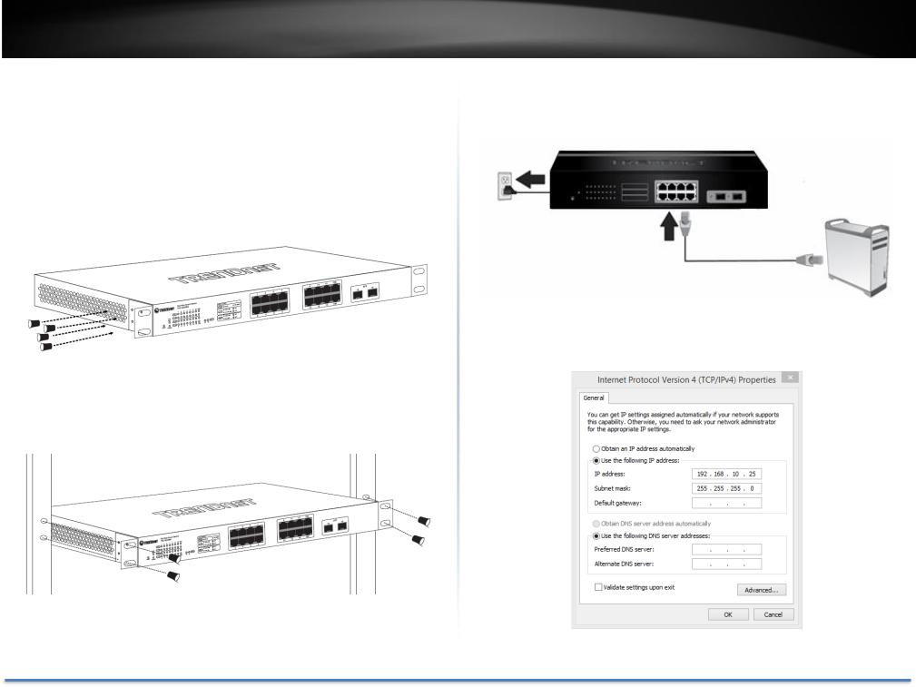
The switch can be mounted in an EIA standard-size, 19-inch rack, which can be placed in a wiring closet with other equipment. Attach the mounting brackets at the switch’s front panel (one on each side), and secure them with the provided screws.
Note: The switch model may be different than the one shown in the example illustrations.
Then, use screws provided with the equipment rack to mount each switch in the rack.
TEG-082WS
Basic Installation
1. Power on your TEG-082WS and connect your computer to the switch.
2.Assign a static IP address to your computer’s network adapter in the subnet of 192.168.10.x (e.g. 192.168.10.25) and a subnet mask of 255.255.255.0.
© Copyright 2014 TRENDnet. All Rights Reserved. |
6 |
TRENDnet User’s Guide
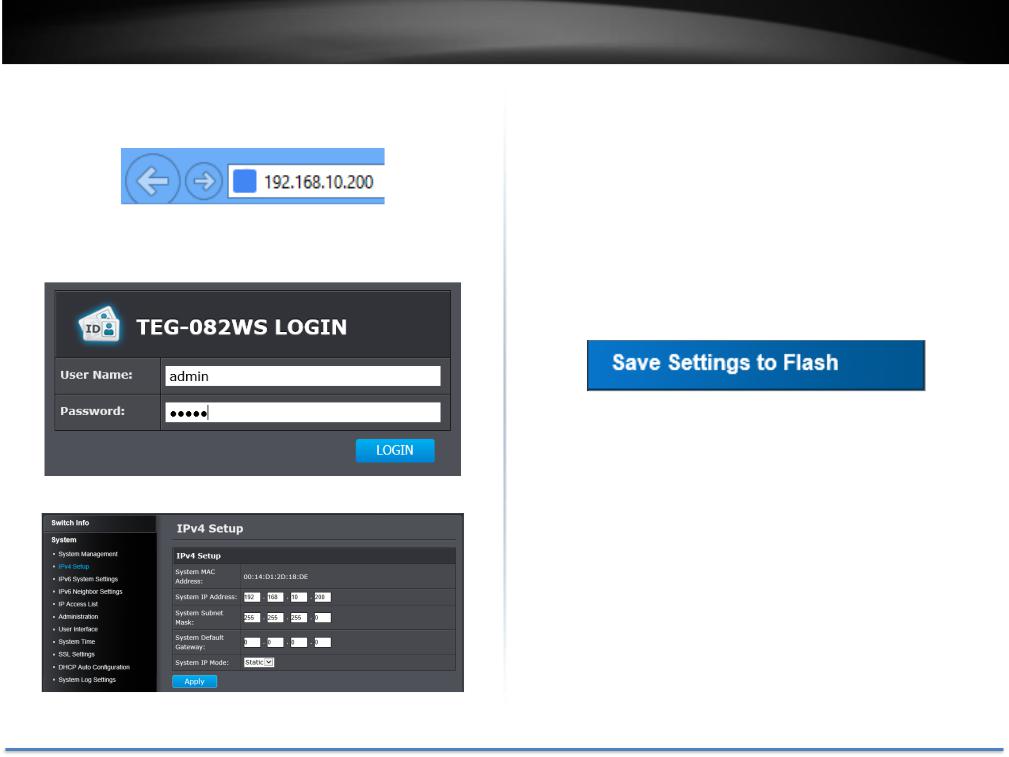
3.Open your web browser, and enter the IP address of the switch, and then press Enter. The default IP address is 192.168.10.200.
4.Enter the User Name and Password, and then click Login. The default username is admin and the password is admin as well. The username and password are case sensitive, please enter them in all lower cases.
5. Click System and then click IPv4 Setup.
TEG-082WS
6.Configure the switch IP address settings to be within your network subnet, then click Apply.
Note: You may need to modify the static IP address settings of your computer’s network adapter to IP address settings within your subnet in order to regain access to the switch.
To store the change to flash memory so you can access the same switch management IP address, please follow the instruction below.
7. Click Save Settings to Flash on the bottom of the menu.
8. Click  button, then click OK.
Note: Once the settings are saved, you can connect the switch to your network.
© Copyright 2014 TRENDnet. All Rights Reserved. |
7 |

TRENDnet User’s Guide |
TEG-082WS |
Connect additional devices to your switch
You can connect additional computers or other network devices to your switch using Ethernet cables to connect them to one of the available Gigabit Ethernet Ports (1-8). Check the status of the LED indicators on the front panel of your switch to ensure the physical cable connection from your computer or device.
Note: If you encounter issues connecting to your network, there may be a problem with your computer or device network settings. Please ensure that your computer or device network settings (also called TCP/IP settings) are configured properly within the network subnet your switch is connected.
© Copyright 2014 TRENDnet. All Rights Reserved. |
8 |

TRENDnet User’s Guide
Configure your switch
Access your switch management page
Note: Your switch default management IP address http://192.168.10.200. You can manage the TEG-082WS websmart switch using Internet web browser on your choice. (e.g. Internet Explorer®, Firefox®, Chrome™, Safari®, or Opera™).
1. Open your web browser and enter the IP address of the switch, such as http://192.168.10.200. Your switch will prompt you for a user name and password.
9.Enter the User Name and Password, and then click Login. The default username is admin and the password is admin as well. The username and password are case sensitive, please enter them in all lower cases.
TEG-082WS
Switch Info
You’ll landing on Switch Info page when login to the web management GUI.
You can view your switch status information here.
© Copyright 2014 TRENDnet. All Rights Reserved. |
9 |
TRENDnet User’s Guide
Switch Information
System Up For: The duration your switch has been running continuously without a restart/power cycle (hard or soft reboot) or reset.
Runtime Image: The current software or firmware version your switch is running.
Boot Loader: The current boot loader version your switch is running.
Hardware Information
DRAM Size: Displays your switch RAM memory size.
Flash Size: Displays your switch Flash memory size.
Administration Information
System Name: Displays the identifying system name of your switch. This information can be modified under the System section.
System Location: Displays the identifying system location of your switch. This information can be modified under the System section.
System Contact: Displays the identifying system contact or system administrator of your switch. This information can be modified under the System section.
System MAC Address, IPv4 Information
MAC Address: |
Displays the switch system MAC address. |
IP Address: |
Displays the current IPv4 address assigned to your |
|
switch. |
Subnet Mask: |
Displays the current IPv4 subnet mask assigned to |
|
your switch. |
TEG-082WS
Default Gateway: Displays the current gateway address assigned to your switch.
IPv6 Information
IPv6 Unicast Address |
Displays the current IPv6 address and prefix |
/ Prefix Length: |
assigned to your switch. |
IPv6 Default |
Displays the current IPv6 default gateway address |
Gateway: |
assigned to your switch. |
Link Local Address / |
Displays the current Link Local address and prefix |
Prefix Length: |
length assigned to your switch. |
Automatic Network Features
IPv4 DHCP Client |
Displays if your switch IPv4 address setting is set to |
Mode: |
DHCP client. |
IPv6 DHCP Client |
Displays if your switch IPv6 address setting is set to |
Mode: |
DHCP client. |
© Copyright 2014 TRENDnet. All Rights Reserved. |
10 |

TRENDnet User’s Guide |
TEG-082WS |
System
System Management
System > System Management
This section explains how to assign a name, location, and contact information for the switch. This information helps in identifying each specific switch among other switches in the same local area network. Entering this information is optional.
Management
System |
Specifies the Switch model. You cannot |
change this |
Description: |
parameter. |
|
System Object |
Indicates the unique SNMP MIB object |
identifier that |
ID: |
identifies the switch model. You cannot change this |
|
|
parameter. |
|
System Name: |
Specifies a name for the switch, the name is optional |
|
|
and may contain up to 15 characters. |
|
System |
Specifies the location of the switch. The |
location is |
Location: |
optional and may contain up to 30 characters. |
|
System Contact: |
Specifies the name of the network administrator |
|
|
responsible for managing the switch. This contact |
|
|
name is optional and may contain up to 30 characters. |
|
Click Apply to apply the change to the switch
Go Save Settings to Flash section to save the change on the flash to make sure the change is permanent.
© Copyright 2014 TRENDnet. All Rights Reserved. |
11 |
TRENDnet User’s Guide
Set your IPv4 settings
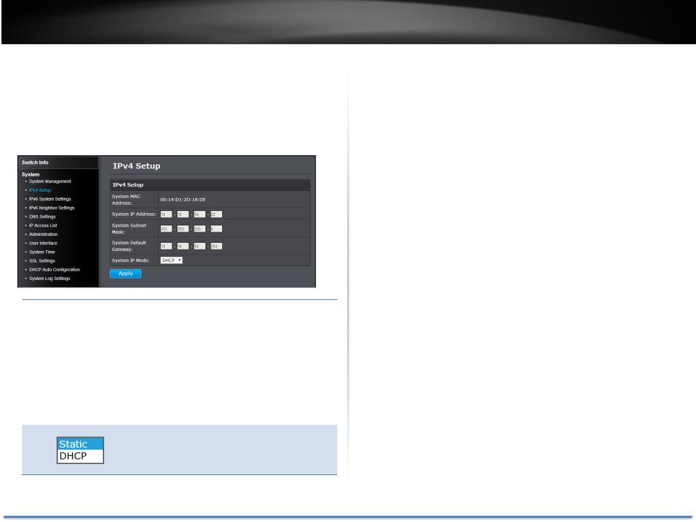
System > IPv4 Setup
This section allows you to change your switch IPv4 address settings. Typically, the IP address settings should be changed to match your existing network subnet in order to access the switch management page on your network.
IPv4 Setup
|
System MAC |
|
|
Displays the switch MAC address information. |
|
|
Address: |
|
|
|
|
|
System IP |
|
Enter the new switch IP address. (Default: |
||
|
Address: |
192.168.10.200) |
|
||
|
System Subnet |
|
|
Enter the new switch subnet mask. (e.g. |
|
|
Mask: |
|
|
255.255.255.0) |
|
|
System Default |
|
Enter the default gateway IP address. (e.g. |
||
|
Gateway: |
|
192.168.10.1 or typically your router/gateway to the |
||
|
|
|
|
Internet). |
|
|
System IP Mode: |
|
|
Click the drop-down list and select Static to |
|
|
|
|
|
manually specify your IP address settings or DHCP to |
|
allow your switch to obtain IP address settings automatically from a DHCP server on your network.
TEG-082WS
Click Apply to apply the change to the switch
Go Save Settings to Flash section to save the change on the flash to make sure the change is permanent.
© Copyright 2014 TRENDnet. All Rights Reserved. |
12 |

TRENDnet User’s Guide
Set your IPv6 settings
System > IPv6 System Settings
Use the IPv6 System Settings page to configure the IPv6 network interface, which is the logical interface used for in-band connectivity with the switch via all of the switch's front-panel ports. The configuration parameters associated with the switch's network interface do not affect the configuration of the front-panel ports through which traffic is switched or routed.
TEG-082WS
IPv6 System Settings
IPv6 State: The IPv6 address for the IPv6 network interface is set in auto configuration mode if this option is enabled. The default value is. Auto configuration can be enabled only when DHCPv6 is not enabled on any of the management interfaces.
DHCPv6 Client: This option only displays when DHCPv6 is enabled. IPv6 Unicast The IPv6 Unicast Address is an identifier for a single Address / Prefix interface, on a single node. A packet that is sent to a
Length: unicast address is delivered to the interface identified by that address. Add the IPv6 prefix and prefix length to the IPv6 System Settings interface.
IPv6 Static Specifies the corresponding Gateway of the IP Gateway: address entered into the field.
IPv6 Dynamic To configure the switch to automatically obtain its IP Gateway: configuration from a DHCP server on your network.
NS Retransmit Time Settings
NS Retransmit A constant that defines a nonzero number of Time: seconds between periodic re-authentication of the
client. The field is 1~3600 seconds. The default setting is 1 second.
Link Local Address Settings
Automatic Link A link local address has a prefix of FE80, is not Local Address: routable, and can be used for communication only
on the local network. Only one link local address is supported. If a link local address exists on the interface, this entry replaces the address in the configuration.
Link Local Enter the Link Local Address/Prefix Length.
Address/Prefix
length:
© Copyright 2014 TRENDnet. All Rights Reserved. |
13 |

TRENDnet User’s Guide
A link-local address is an IPv6 unicast address that can be automatically configured on any interface using the link-local prefix FE80/10 and the interface identifier in the modified EUI-64 format. Link-local addresses are used in the neighbor discovery protocol and the stateless auto configuration process. Nodes on a local link can use link-local addresses to communicate; the nodes do not need globally unique addresses to communicate. IPv6 devices must not forward packets that have link-local source or destination addresses to other links.
Click Apply to apply the change to the switch.
Go Save Settings to Flash section to save the change on the flash to make sure the change is permanent.
TEG-082WS
DNS Settings
System > DNS Settings
Some of the smart switch services requires name resolution services to finish its job, such as SNTP service. Setup the DNS server settings here for name resolution.
DNS Server Settings
DNS IPv4 Server: Specifies the IPv4 DNS server address. DNS IPv6 Server: Specifies the IPv6 DNS server address.
Click Add to save the entry to the list.
Go Save Settings to Flash section to save the change on the flash to make sure the change is permanent.
© Copyright 2014 TRENDnet. All Rights Reserved. |
14 |

TRENDnet User’s Guide
Add IPv6 neighbors
System > IPv6 Neighbor Settings
These settings allows you to manually define IPv6 supported neighboring devices on your network.
IPv6 Neighbor Settings
Neighbor IPv6 Specifies the neighbor IPv6 address.
Address:
Link Layer MAC Specifies the link layer MAC address.
Address:
Click Add to save the entry to the list.
You can type in the specific address and click Find to find the entry to modify or click Delete to delete the address. If the entries span multiple pages, you can navigate page number in the Page field and click Go or you can click First, Previous, Next, and Last Page to navigate the pages.
Go Save Settings to Flash section to save the change on the flash to make sure the change is permanent.
TEG-082WS
Restrict access to switch management page
System > IP Access List
This section allows you to define or restrict access to the switch management page to a list of specific IP addresses.
IP Access List
IP Restriction Enable or disable Access Control List. Default: Status: Disabled
IP Address Settings
IP Address: Enter the IPv4 or IPv6 address and then click Add to create an access list entry.
© Copyright 2014 TRENDnet. All Rights Reserved. |
15 |

TRENDnet User’s Guide
IP Access List Table
For each entry, the access list will populate. You can click Delete next to the entry to delete the entry or Delete All to delete all entries in the table.
When you have completed entering the IPv4 and IPv6 address entries, click the IP Restriction Status drop-down list at the top and select Enabled, then click Apply.
Go Save Settings to Flash section to save the change on the flash to make sure the change is permanent.
TEG-082WS
Change administrator password and add accounts
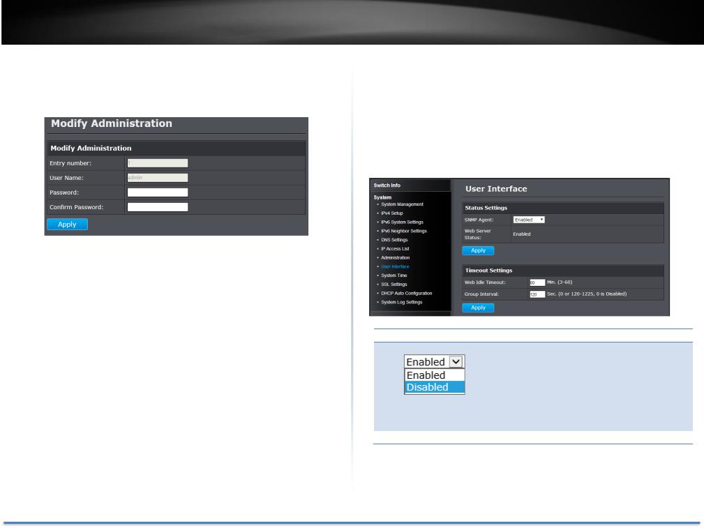
System > Administration
This section explains how to change the administrator password create additional administrative user accounts for access to the switch management page.
To create additional administrative user accounts
Administration Settings
User Name: Enter the user name of the new account. Password: Enter the password for the new account Confirm Password: Enter the password again for verification.
Note: The password consists of up to 12 alphanumeric characters.
Click Add to add the new administrator.
© Copyright 2014 TRENDnet. All Rights Reserved. |
16 |
TRENDnet User’s Guide
Changing the administrator password
In the Password field, enter the new password and enter the new password again the Confirm Password field to verify. Then, click Apply.
Note: The password consists of up to 12 alphanumeric characters. The index 1 admin user on the administration table is the default administrator. You can modify the password, but you cannot remove it.
Go Save Settings to Flash section to save the change on the flash to make sure the change is permanent.
TEG-082WS
Enable or disable SNMP and modify idle timeout settings
System > User Interface
This section explains how to enable SNMP on the switch and modify the switch management page idle timeout settings.
Note: If you disable the SNMP on the switch, the switch will not be manageable via SNMP using MIBs.
Status Settings
SNMP Agent: Click the drop-down list to one of the following options.
Enabled: The SNMP agent is active. You can manage the switch with SNMP network management software and the switch’s private
MIB.
Disabled: The SNMP agent is inactive.
Web Server Status: Displays the current SNMP status.
© Copyright 2014 TRENDnet. All Rights Reserved. |
17 |
TRENDnet User’s Guide
Timeout Settings
Web Idle Timeout: Enter the idle period in minutes, when the switch will automatically log out an idled user from the switch management page. Default: 10 min.
Group Interval: The IGMP group timeout interval. Default: 120 sec.
Click Apply to apply the change to the switch
Go Save Settings to Flash section to save the change on the flash to make sure the change is permanent.
TEG-082WS
Set the switch date and time
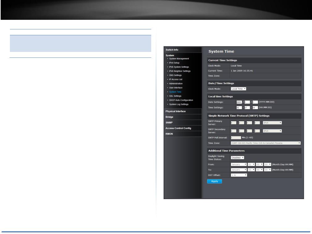
System > System Time
© Copyright 2014 TRENDnet. All Rights Reserved. |
18 |

TRENDnet User’s Guide
Current Time Settings
Clock Mode: Displays if system time and date is set manually Local Time or obtained automatically from a network time server SNTP.
Current Time: Displays the current system time and date. Time Zone: Displays the current system time zone.
Date/Time Settings
Clock Mode: Select Local Time to manually configure your date and time settings or select SNTP to configure your switch to automatically obtain settings from a network time server.
Local Time Settings
Date Settings: Enter your date settings (YYYY/MM/DD).
Time Settings: Enter your time settings (HH:MM:SS)
When select the clock mode to Local Time, enter the date and time manually here.
Simple Network Time Protocol (SNTP) Settings
SNTP Primary Select the format of the URL you want to enter for Server: SNTP server address. Enter the primary network time
server IPv4, IPv6 address or domain name.
SNTP Secondary Select the format of the URL you want to enter for Server: SNTP server address. Enter the secondary network
time server IPv4, IPv6 address or domain name.
TEG-082WS
SNTP Poll Enter the interval time when your switch will update Interval: the time and date settings with the time server.
Default: 1 min.
Time Zone Click the drop-down list to select your time zone.
When select the clock mode to SNTP, enter the SNTP server information here.
Click Apply to apply the change to the switch
Go Save Settings to Flash section to save the change on the flash to make sure the change is permanent.
© Copyright 2014 TRENDnet. All Rights Reserved. |
19 |
TRENDnet User’s Guide
Enable HTTPS/SSL (Secure Socket Layer) management access
System > SSL Settings
By default, your switch management page can be accessed using standard web HTTP protocol which transmit files with clear text over the network. Enabling HTTPS/SSL management access allows access to the switch management page using encrypted communication prevents your data been eavesdropped by unauthorized user.
Note: Once HTTPS/SSL management access is enabled, HTTP management access will be disabled forcing all access to the switch management page using secure encryption communication only.
SSL Settings
SSL Status: Enable or disable HTTPS/SSL management access or to HTTP clear text mode. Default: Disabled.
Note: When SSL is enabled, you need to access the switch management page using HTTPS instead of HTTP. (e.g. https://192.168.10.200)
TEG-082WS
Click Apply to apply the change to the switch
Go Save Settings to Flash section to save the change on the flash to make sure the change is permanent.
© Copyright 2014 TRENDnet. All Rights Reserved. |
20 |
TRENDnet User’s Guide
Enable DHCP Auto Configuration
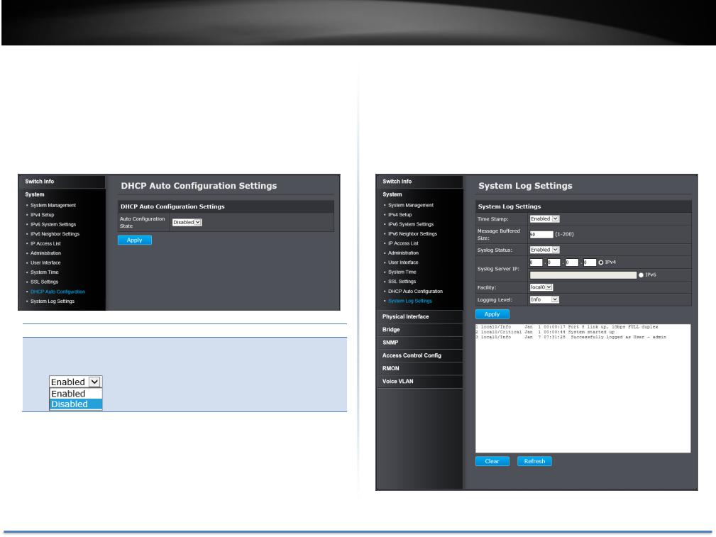
System > DHCP Auto Configuration
If you need to synchronize the switch configuration file on remote server, the DHCP Auto Configuration feature is available for this purpose via the DHCP server. Your IP address settings must enabled to the DHCP client so that this feature can operate with your DHCP/TFTP server.
DHCP Auto Configuration Settings
Auto Enable/Disable Auto Configuration from DHCP/TFTP Configuration server. Default: Disabled.
State:
Click Apply to apply the change to the switch
Go Save Settings to Flash section to save the change on the flash to make sure the change is permanent.
TEG-082WS
View and setup your switch logging
System > System Log Settings
The system log is designed to monitor the operation the switch by recording the event messages it generates during normal operation. These events may provide vital information about system activity that can help in the identification and solutions of system problems.
© Copyright 2014 TRENDnet. All Rights Reserved. |
21 |
TRENDnet User’s Guide
System Log Settings
Time Stamp: Enable/Disable the time stamp on log entry. Default: Enabled.
Message Enter the message buffer size. Default: 50 entries,
Buffered Size: Range: 1-200.
Syslog Status: Enable/ Disable to store the logs on remote log server. Default: Enabled.
Syslog Server IP: Enter the IPv4 or IPv6 address of the external syslog server to send logging.
Facility: Click the drop-down list and which facility to store the logging. (Options: local0 – local7)
Note: You can define the facility to store logging on your external syslog server. This helps to ensure you have separate logging sections for different devices.
Logging Level: Click the drop-down list to select what level of event messages that will be logged.
0. Emergency: The system is unusable.
1. Alert: Action must be taken immediately.
2. Critical: Critical conditions are displayed.
3. Error: Error conditions are displayed.
4. Warning: Warning conditions are displayed.
5. Notice: Normal but significant conditions are displayed.
6. Informational: Informational messages are displayed.
7. Debug: Debug-level messages are displayed.
Click Apply to apply the change to the switch
Go Save Settings to Flash section to save the change on the flash to make sure the change is permanent.
TEG-082WS
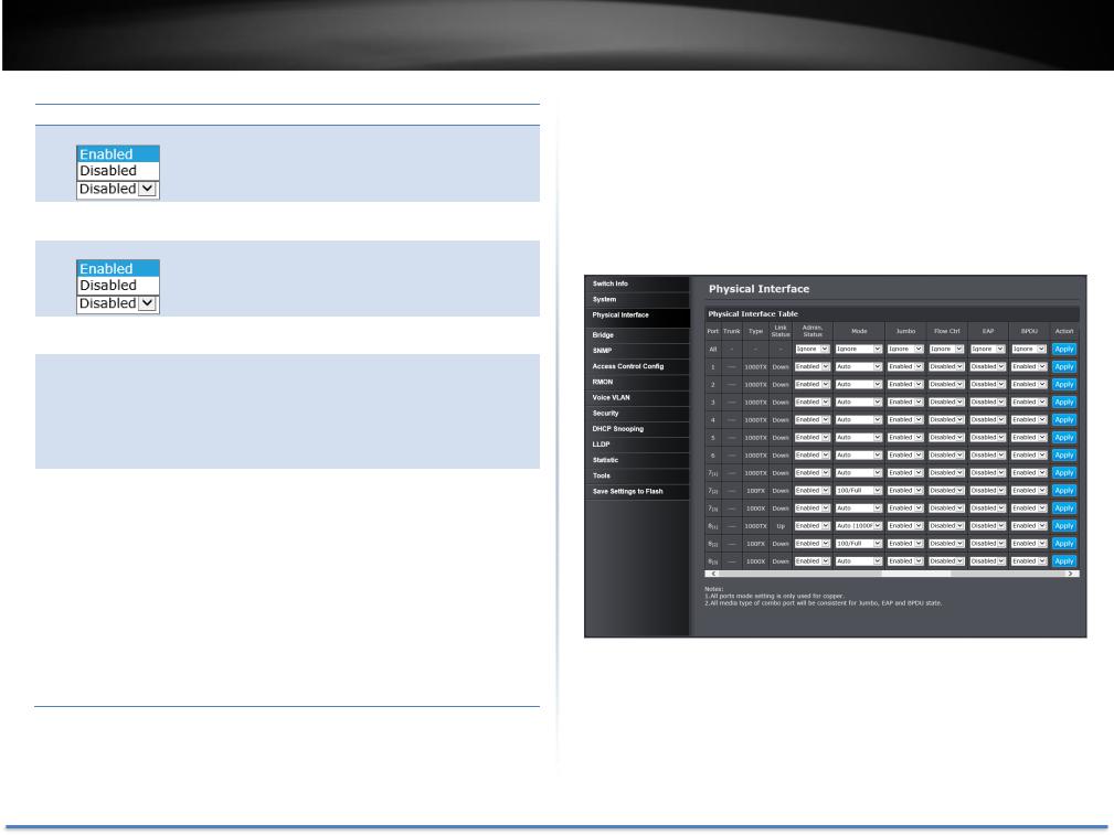
Physical Interface
This section allows you to configure the physical port parameters such as speed, duplex, flow control, and jumbo frames. This section also reports the current link status of each port and negotiated speed/duplex. Additionally you will be able to set your BPDU ports for Spanning Tree Configuration and EAP ports for 802.1X port-based authentication configuration.
© Copyright 2014 TRENDnet. All Rights Reserved. |
22 |

TRENDnet User’s Guide
Physical Interface Table
Port: Specifies the port number. The All value indicates ports 1 through 8 on the Switch. The port number 7 and 8 are Gigabit and SFP shared ports. Only one interface will be activated at the same time. When SFP and Gigabit connection coexist, the SFP will take the priority.
(1)Gigabit Port
(2)SFP with 100FX module
(3)SFP with 1000X module
Trunk: This cell displays the trunk status with trunk group number. A number in this column indicates that the port has been added to a trunk using static or dynamic 802.3ad LACP link aggregation.
Type: This cell displays the port type. On the Switch, the port type is 1000TX for 10/100/1000Base-T twisted-pair ports (1-8) and 100FX or 1000X for the SFP ports (7F-8F) for copper or fiber SFP type.
Link Status: This cell displays the network link status of the port. The possible values are:
Up: This value indicates a valid link exists between the port and the end node.
Down: This value indicates the port and the end node have not established a valid link.
Admin Status: This parameter indicates the operating status of the port. You can use this parameter to enable or disable a port. You may want to disable a port and prevent packets from
being forwarded if a problem occurs with the node or cable connected to the port. You can enable the port to resume normal operation after the problem has been fixed. You can also disable an unused port to secure it from unauthorized connections.
All Ports:
If you select Ignore and click on Apply for all ports, the Admin Status is not changing. If you select Enabled then
TEG-082WS
click on Apply for all ports, Admin Status on all ports will be set to Enabled.
Each Port:
Enabled: This port is enabled to send and receive Ethernet frames.
Disabled: This port is disabled and cannot send and
receive Ethernet frames.
Note: Click Apply in the end of the row to apply the change.
Mode: This parameter indicates the speed and duplex mode settings for the port. You can use this parameter to set the speed and duplex mode of a port.
All Ports:
If you select Ignore and click on Apply for all ports, the Mode is not changing. If you set to certain mode then click on Apply for all ports, the Mode on all ports will be set to the same value.
Each Port:
Auto: This parameter indicates the port is using AutoNegotiation to set the operating speed and duplex mode. The actual operating speed and duplex mode of the port are displayed in parentheses (for example,
“1000F” for 1000 Mbps full duplex mode) after a port establishes a link with an end node.
o Auto (1000F): This parameter indicates the port is configured for 1000Mbps operation in AutoNegotiation mode.
o 1000/Full -This parameter indicates the port is configured for 1000Mbps operation in full-duplex mode.
o 100/Full -This parameter indicates the port is configured for 100Mbps operation in full-duplex mode.
© Copyright 2014 TRENDnet. All Rights Reserved. |
23 |

TRENDnet User’s Guide
o 10/Full -This parameter indicates the port is configured for 10Mbps operation in full-duplex mode.
o 1000/Half -This parameter indicates the port is configured for 1000Mbps operation in half-duplex mode.
o 100/Half -This parameter indicates the port is configured for 100Mbps operation in half-duplex mode.
o10/Half -This parameter indicates the port is configured for 10Mbps operation in half-duplex mode.
Note: When selecting a Mode setting, the following points apply:
oWhen a twisted-pair port is set to Auto-Negotiation, the end node should also be set to Auto-Negotiation to prevent a duplex mode mismatch.
oA switch port using Auto-Negotiation defaults to halfduplex if it detects that the end node is not using AutoNegotiation. This can result in a mismatch if the end node is operating at a fixed duplex mode of full-duplex. To avoid this problem when connecting an end node with a fixed duplex mode of full-duplex to a switch port, disable Auto-Negotiation on the port and set the port’s speed
and duplex mode manually.
oThe only valid setting for the SFP ports is AutoNegotiation.
Note: Click Apply in the end of the row to apply the change.
Jumbo: This parameter indicates whether or not jumbo frames can be accepted by the switch. You may want to activate jumbo frames when your switch will transmit video and audio files.
TEG-082WS
All Ports:
If you select Ignore and click on Apply for all ports, the Jumbo setting is not changing. If you select Enabled or Disabled then click on Apply for all ports, Jumbo setting on all ports will be set to the same value on Enabled or
Disabled.
Each Port:
Enabled: This port is enabled to send and receive Jumbo frames.
Disabled: This port is disabled and cannot send and
receive Jumbo frames.
Note:
1)Click Apply in the end of the row to apply the change.
2)When QoS is enabled on a port, the Jumbo frame parameter cannot be enabled.
Flow Ctrl: Flow Control, This parameter shows the current flow control setting on the port. The switch uses a special pause packet to notify the end node to stop transmitting for a specified period of time.
All Ports:
If you select Ignore and click on Apply for all ports, the Flow Control setting is not changing. If you select Enabled or Disabled then click on Apply for all ports, Flow Control setting on all ports will be set to the same value on
Enabled or Disabled.
Each Port:
Enabled: This port is enabled to proceed the flow control.
Disabled: This port is disabled and not doing flow control.
Note: Click Apply in the end of the row to apply the change.
© Copyright 2014 TRENDnet. All Rights Reserved. |
24 |

TRENDnet User’s Guide
EAP: This number shows the current Extensible
Authentication Protocol (EAP) setting on the port.
All Ports:
If you select Ignore and click on Apply for all ports, the EAP setting is not changing. If you select Enabled or Disabled then click on Apply for all ports, EAP setting on all ports will be set to the same value on Enabled or
Disabled.
Each Port:
Enabled: This port is enabled to send and receive EAP packets.
Disabled: This port is disabled and will not send and receive EAP packets.
Note: Click Apply in the end of the row to apply the change.
BPDU: This parameter shows the current BPDU setting on the port.
All Ports:
If you select Ignore and click on Apply for all ports, the BPDU setting is not changing. If you select Enabled or Disabled then click on Apply for all ports, BPDU setting on all ports will be set to the same value on Enabled or
Disabled.
Each Port:
Enabled: This port is enabled to pass BPDU frames through the switch and broadcast them through all other ports.
Disabled: This port is disabled and the switch will not pass BPDU frames through the switch. With RSTP or STP enabled, the switch will receive BPDU frames and process them according to the spanning tree protocol.
TEG-082WS
Note: Click Apply in the end of the row to apply the change.
Go Save Settings to Flash section to save the change on the flash to make sure the change is permanent.
© Copyright 2014 TRENDnet. All Rights Reserved. |
25 |
TRENDnet User’s Guide
Bridge
The Bridge session covers most of the web smart switch features including spanning tree, trunk configuration, IGMP snooping, bandwidth control, VLAN, VGRP, and QoS.
Spanning Tree (STP, RSTP, MSTP)
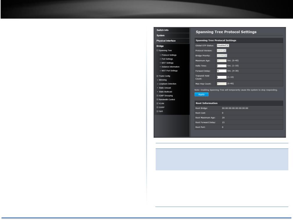
Configure Spanning Tree Protocol settings
Bridge > Spanning Tree > Protocol Settings
Spanning Tree Protocol (STP) provides network topology for any arrangement of bridges/switches. STP also provides a single path between end stations on a network, eliminating loops. Loops occur when alternate routes exist between hosts. Loops in an extended network can cause bridges to forward traffic indefinitely, resulting in increased traffic and reducing network efficiency.
TEG-082WS
Spanning Tree Protocol Settings
Global STP Select the STP state on the device.
Status: Disable: Disables STP on the device. This is the default value.
Enable: Enables STP on the device.
Protocol Version: Specifies the Spanning Tree Protocol (STP) mode to enable on the switch.
STP: Enables STP 802.1D on the device.
RSTP: Enables Rapid STP 802.1w on the device. This is the default value.
MSTP: Enables Multiple STP 802.1s on the device.
© Copyright 2014 TRENDnet. All Rights Reserved. |
26 |
TRENDnet User’s Guide
Bridge Priority: The Bridge Priority has a range 0 to 61440 in
increments of 4096. To make this easier for you, the Web Management Utility divides the range into increments. You specify the increment that represents the desired bridge priority value.
Maximum Age: The Maximum Age defines the amount of time a port will wait for STP/RSTP information. MSTP uses this parameter when interacting with STP/RSTP domains on the boundary ports. Its range is 6 - 40 seconds
Hello Time: The Hello Time is frequency with which the root bridge sends out a BPDU.
Forward Delay: The Forward Delay defines the time that the bridge spends in the listening and learning states. Its range is 4 - 30 seconds.
Transmit Hold The Transmit Hold Count specifies the maximum Count: number of BPDUs that the bridge can send per second.
Its range is 1 - 10.
Max Hop Count: The Max Hop Count is a parameter set in a BPDU packet when it originates. It is decremented by 1 each time it is retransmitted by the next bridge. When the Hop Count value reaches zero, the bridge drops the BPDU packet. Its range is 6 - 40 hops.
Root Information
Root Bridge: The root bridge ID in the spanning tree.
Root Cost: The connection cost on the root port
Root Maximum The aging timeout for the root port.
Age:
Root Forward The forward delay timer before packet forwarding.
Delay:
Root Port: The port number been assigned as root port. Click Apply to apply the change to the switch
Go Save Settings to Flash section to save the change on the flash to make sure the change is permanent.
TEG-082WS
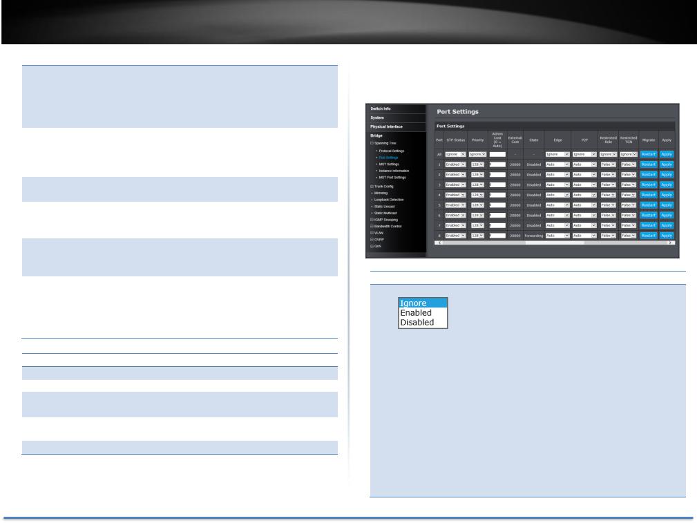
Configure Spanning Tree Protocol port settings
Bridge > Spanning Tree > Port Settings
Port Settings
STP Status: Indicates if spanning tree protocol is active or not on the port.
All Ports:
If you select Ignore and click on Apply for all ports, the STP Status setting is not changing. If you select Enabled or Disabled then click on Apply for all ports, STP Status setting on all ports will be set to the same value on Enabled or Disabled.
Each Port:
Enable: The spanning tree protocol is enabled on the port.
Disabled: The spanning tree protocol is disabled on the port. Enable Disable
© Copyright 2014 TRENDnet. All Rights Reserved. |
27 |

TRENDnet User’s Guide
|
|
|
Note: Click Apply in the end of the row to apply the change. |
|
|
|
|
BPDU pass-through must be disabled for all ports under |
|
|
|
|
Physical interface for STP can be enabled. |
|
|
|
|
|
|
|
Priority: |
Indicates the port priority. If two paths have the same |
||
|
|
|
port cost, the bridges must select a preferred path. In |
|
|
|
|
some instances this can involve the use of the port |
|
|
|
|
priority parameter which is used as a tie breaker when |
|
|
|
|
two paths have the same cost. |
|
|
|
|
The range for port priority is 0 to 240. As with bridge |
|
|
|
|
priority, this range is broken into increments, in this |
|
|
|
|
case multiples of 16. To select a port priority for a port, |
|
|
|
|
select a desired value. |
|
|
|
|
Note: Click Apply in the end of the row to apply the change. |
|
|
|
|
If you select Ignore on All Ports and click on Apply for all |
|
|
|
|
ports, the Admin Cost setting is not changing. If you set the |
|
|
|
|
value then click on Apply for all ports, The Admin Cost will |
|
|
|
|
be set to the same value. |
|
|
|
|
||
|
Admin Cost |
|
The administratively assigned value for the |
|
(0 = Auto): contribution of this port to the path cost of a port. Writing a value of '0' assigns the automatically calculated default path cost value to the port. If the default path cost is being used, this object returns '0' when read.
External Cost: This defines a metric that indicates the relative cost of forwarding packets to the specified port list. Port cost can be set automatically or as a metric value. Define a value between 1 and 200,000,000 to determine the external cost. The default port cost: 100Mbps port = 200,000. Gigabit port = 20,000.
State: Displays the current port spanning tree state.
Blocking: A blocking state does not allow network traffic to be sent or received on the port except for BPDU data. A port with a higher path cost to the root
TEG-082WS
bridge than another on the switch causes a switching
loop and is placed in the blocking state by the
Spanning Tree algorithm. The port’s state may change to the forwarding state if the other links in use fail and the Spanning Tree algorithm determines the port may transition to the forwarding state.
Listening: This state occurs on a port during the convergence process. The port in the listening state processes BPDUs and awaits new information that would cause the port to return to the blocking state.
Learning: While the port does not yet forward frames (packets), in this state the port does learn source addresses from frames received and adds them to the filtering (switching) database.
Forwarding: A port that both receives and sends data. This indicates normal operation. STP continues to monitor the port for incoming BPDUs that indicate the port should return to the blocking state to prevent a loop.
Disabled: A port with STP disabled does not participate in STP. A network administrator can manually disable a port.
Edge: Indicates if a port is connected to an edge device in the network topology or not. Selecting the ForceTrue to assign the port as an edge port. Edge ports cannot create loops, however an edge port can lose edge port status if a topology change creates a potential for a loop. An edge port normally should not receive BPDU packets. If a BPDU packet is received, it automatically loses edge port status. Selecting the ForceFalse indicates that the port does not have edge port status. Selecting the Auto parameter indicates that the port have edge port status or not have edge port status
© Copyright 2014 TRENDnet. All Rights Reserved. |
28 |
TRENDnet User’s Guide
automatically. The default setting for this parameter is
Auto.
Note: Click Apply in the end of the row to apply the change. If you select Ignore on All Ports and click on Apply for all ports, the Admin Cost setting is not changing. If you set the value then click on Apply for all ports, The Admin Cost will be set to the same value.
P2P: Choosing the Forcetrue parameter indicates a point- to-point (P2P) shared link. P2P ports are similar to edge ports however they are restricted in that a P2P port must operate in full-duplex.
Like edge ports, P2P ports transition to a forwarding state rapidly thus benefiting from RSTP. A P2P value of Forcefalse indicates that the port cannot have P2P status. Auto allows the port to have P2P status whenever possible and operate as if the P2P status were true. If the port cannot maintain this status, (for example if the port is forced to half-duplex operation) the P2P status changes to operate as if the P2P value were Forcefalse.
The default setting for this parameter is Auto.
Restricted Role: Toggle between True and False to set the restricted role state of the packet. If set to True, the port will never be selected to be the Root port. The default value is False.
Restricted TCN: Toggle between True and False to set the restricted TCN of the packet. Topology Change Notification (TCN) is a BPDU that a bridge sends out to its root port to signal a topology change. If set to True, it stops the port from propagating received TCN and to other ports. The default value is False.
TEG-082WS
Migrate: Indicates if the port is configured to accept RSTP and STP BPDUs.
Go Save Settings to Flash section to save the change on the flash to make sure the change is permanent.
© Copyright 2014 TRENDnet. All Rights Reserved. |
29 |
Loading...