


|
|
|
|
|
|
C |
|
|
|
|
|
-(Three |
|
|
|
A |
|
|
|
|
(62.44) |
1,480 |
|
|
Dimensional |
|
|
|
|
|
685 |
|
|
|
(58.27) |
|
c |
|
|
|
|
|
|
|
|
|
|
|
|
||
|
|
|
|
(26.97) |
|
|
|
|
|
|
|
|
|
|
|
|
|
|
|
|
1,586 |
D |
|
|
|
|
|
|
|
|
|
913 |
761 |
|
|
|
Distance) |
|
|
|
|
|
|
|
|
(50.16) |
|
|
|||
|
|
|
|
|
L |
|
(29.96) |
|
|
|
|
|
|
|
|
|
|
|
|
|
1,274 |
|
|
|
|
|
|
|
|
|
|
|
|
|
|
|
|
|
|
|
|
K |
|
|
(35.94) |
B |
|
1,036 |
564 |
302 |
|
|
|
|
|
|
|
|
|
|
(22.20) |
(11.89) |
|
|
|
|
|
|
|
|
1,383 |
|
753 |
(40.79) |
|
b |
|
|
|
|
|
|
|
|
|
|
l |
|
||
|
|
|
I |
|
|
(54.45) |
938 |
(29.65) |
1,055 |
|
|
|
|
|
|
|
|
|
|
(41.54) |
|
|
|
||
|
|
|
|
G |
|
|
(36.93) |
|
|
a |
|
|
|
|
|
675 |
|
|
F |
|
|
|
|
||
|
|
|
(26.57) |
|
|
|
|
|
|
k |
|
|
|
|
|
|
|
E |
|
760 |
|
|
i |
|
|
|
|
|
|
|
|
|
|
|
|
|||
|
|
|
H |
|
|
(29.92) |
g |
|
|
|
||
|
|
|
|
|
|
882 |
|
f |
|
|
||
|
|
|
|
|
467 |
|
|
|
|
|
||
|
|
|
|
|
(34.72) |
|
|
|
|
|
||
|
|
|
|
|
(18.39) |
788 |
809 |
h |
|
|
|
|
|
|
|
|
|
(31.02) |
e |
|
|
|
|||
|
|
|
|
|
|
|
(31.85) |
|
|
|
|
|
|
|
|
|
|
J |
|
|
338 |
|
|
|
|
|
|
|
|
|
|
|
(13.31) |
|
|
|
|
|
|
|
C-K |
C-L |
C-k |
C-l |
j |
|
|
|
|
||
K-k |
L-l |
|
|
|
|
|
||||||
or |
or |
|
or |
or |
|
|
|
|
|
|
||
|
|
c-k |
c-l |
|
c-K |
c-L |
|
|
|
|
|
|
1,519 |
1,439 |
674 |
335 |
|
1,644 |
1,497 |
|
HINT: |
For symbols, capital letters indicate right side of vehicle, |
|
||
(59.80) |
(56.65) |
(26.54) |
(13.19) |
(64.72) |
(58.94) |
|
small letters indicate left side of vehicle (Seen from rear). |
mm (in.) |
||||
|
|
|
|
|
|
|
|
|
|
|
|
|
Symbol |
|
|
|
Name |
|
|
Hole dia. |
Symbol |
|
Name |
Hole dia. |
|
A, a |
Front fender installation nut |
|
|
|
|
6 (0.24) nut |
G, g |
Radiator support standard hole |
10 (0.39) |
|||
B, b |
Front spring support hole-inner |
|
|
|
11 (0.43) |
H, h |
Radiator support standard hole |
10 (0.39) |
||||
C, c |
Hood hinge installation nut-rear |
|
|
|
8 (0.31) nut |
I, i |
Radiator support standard hole |
10 (0.39) |
||||
D |
Cowl top panel vehicle center mark |
|
|
3 (0.12) R |
J, j |
Front crossmember standard hole |
12 (0.47) |
|||||
E, e |
Front side member standard hole |
|
|
|
13 (0.51) |
K, k |
Front fender apron cut-out portion |
— |
||||
F, f |
Front side member standard hole |
|
|
|
17 (0.67) |
L, l |
Front fender installation nut |
6 (0.24) nut |
||||
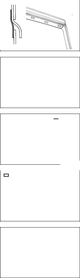
COMPARTMENT ENGINE |
DRAWINGS DIMENSION BODY |
Drawings Dimension Body - DIMENSIONS BODY |
3-DI

BO-45
BODY - REAR WIPER AND WASHER
BO23Z-01
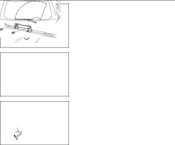
INSTALLATION
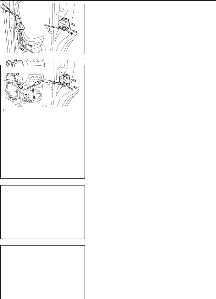
1.INSTALL WASHER NOZZLE
2.INSTALL WIPER MOTOR AND LINK ASSEMBLY
(a)Install the grommet.
(b)Install the wiper motor and link assembly with 5 bolts.
Torque: 5.4 N·m (55 kgf·cm, 48 in.·lbf)
(c)Connect the connector.
|
|
H02639 |
|
|
|
|
3. INSTALL BACK DOOR TRIM BOARD |
|
: 11 Clips |
|
|
|
|
|
Install the door trim board to the back door panel. |
|
|
|
|
H02352
: 3 Clips |
4. |
INSTALL SIDE GARNISH |
|
(a) |
Install the side garnish to the back door panel. |
|
(b) |
Employ the same manner described above to the other |
|
|
side. |
|
|
H02351 |
|
|
|
|
5. INSTALL CENTER GARNISH |
|
|
|
|
|
: 5 Clips |
|
|
|
|
|
Install the center garnish to the back door panel. |
|
|
|
|
H02350
2001 SIENNA (RM787U)
Author!: |
Date!: |
1722 |
BO-46
BODY - REAR WIPER AND WASHER
6.INSTALL BACK DOOR PULL STRAP
(a)Install the back door pull strap with the screw.
(b)Install the strap cover.
H02349
7.INSTALL BACK DOOR ASSIST GRIP
(a)Install the back door assist grip with the 2 screws.
(b)Close the covers.
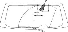
8.INSTALL WIPER ARM
(a)Operate the wiper once and turn the wiper switch OFF.
(b)Install the wiper arm and tighten nuts by hand.
H02348
Defogger
Line
A 
H02370
(c)Adjust the installation position of the wiper arm to the position shown in the illustration.
A: 38.6 mm (1.520 in.)
(d)Torque the nut.
Torque: 5.4 N·m (55 kgf·cm, 48 in.·lbf)
2001 SIENNA (RM787U)
Author!: |
Date!: |
1723 |
BE-159
BODY ELECTRICAL - ENGINE IMMOBILISER SYSTEM
BE0B4-09
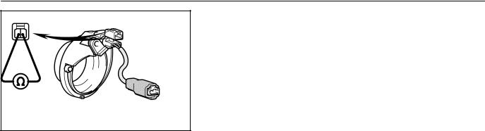
INSPECTION
INSPECTION TRANSPONDER KEY COIL CONTINUITY
Check that continuity exists between terminal 1 and 2.
If continuity is not as specified, replace the coil.
I03099
2001 SIENNA (RM787U)
Author!: |
Date!: |
1677 |

BO-38
BODY - FRONT WIPER AND WASHER
BO0SF-02
A |
A |
B |
B |
|
|
|
|
|
K |
|
E |
D |
C |
|
G |
D |
|
G |
|
|
H |
F |
|
L |
H |
|
M J |
J I |
H02366 |
INSPECTION
INSPECT WASHER NOZZLE
While operating the washer, check that the upper point where the washer fluid hits the windshield and the surge area are within the range indicated by the hatched line.
A:Approx. 150 mm (5.91 in.)
B:Approx. 50 mm (1.97 in.)
C:Approx. 0 - 50 mm (0 - 1.97 in.)
D:Approx. 120 mm (4.72 in.)
E:Approx. 299 mm (11.77 in.)
F:Approx. 167 mm (6.57 in.)
G:Approx. 65 mm (2.56 in.)
H:Approx.105 mm (4.13 in.)
I:Approx. 61 mm (2.40 in.)
J:Approx. 300 mm (11.81 in.)
K:Approx. 221 mm (8.70 in.)
L:Approx. 251 mm (9.88 in.)
M:Approx. 37 mm (1.46 in.)
2001 SIENNA (RM787U)
Author!: |
Date!: |
1715 |
BO-44
|
|
|
BODY - REAR WIPER AND WASHER |
|
|
|
|
BO0SJ-02 |
|
|
|
|
INSPECTION |
|
|
|
|
||
|
|
|
INSPECT REAR WASHER NOZZLE |
|
B |
A |
|
While operating the washer, check if the point where the washer |
|
C |
D |
|
fluid hits the back door glass is within the range indicated by the |
|
|
|
hatched line. |
||
|
|
|
||
|
|
|
A: Approx. 152 mm (5.98 in.) |
|
|
|
|
B: Approx. 115 mm (4.53 in.) |
|
|
|
|
C: Approx. 110 mm (4.33 in.) |
|
|
|
H02369 |
D: Approx. 183 mm (7.20 in.) |
|
|
|
|
|
|
2001 SIENNA (RM787U)
Author!: |
Date!: |
1721 |

BE-147
BODY ELECTRICAL - GARAGE DOOR OPENER SYSTEM
BE0G5-05
INSPECTION
1. INSPECT GARAGE DOOR OPENER SWITCH
Press the switch and check that each LED (red) lights up. Even if only one switch is found not to light up, replace it.
I19482
|
2. |
INSPECT GARAGE DOOR OPENER REGISTRATION |
|
HINT: |
AND TRANSMITTING |
|
|
|
|
Use the home link tester made by KENT MORE for this test. |
|
|
As it is necessary to record the code of the hand held transmit- |
|
|
ter, customer’s code will be erased. When the inspection com- |
|
|
pletes, please register the customer’s again. |
|
|
(a) |
Check that the code of hand held transmitter for inspec- |
I19483 |
|
tion can be recorded (See page BE-142 ). |
If the code can not be registered, replace garage door opener.
(b)Press the switch which an inspection code has been registered for and check that LED (green) of the home link
tester lights up.
If the LED (green) does not light up, replace the garage door opener.
I19484
2001 SIENNA (RM787U)
Author!: |
Date!: |
1665 |
BE-148
BODY ELECTRICAL - GARAGE DOOR OPENER SYSTEM
Wire Harness Side |
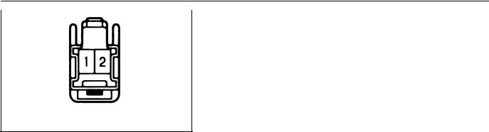
3. INSPECT GARAGE DOOR OPENER SWITCH CIRCUIT |
|
Disconnect the connector from the switch and inspect the con- |
||
|
||
|
nector on the wire harness side, as shown. |
I04194
Tester connection |
Condition |
Specified condition |
1 - Ground |
Constant |
Continuity |
2 - Ground |
Constant |
Battery positive voltage |
If the circuit is not as specified, inspect the power source or wire harness.
2001 SIENNA (RM787U)
Author!: |
Date!: |
1666 |
BO-19
|
|
|
BODY - SLIDE DOOR |
|
|
|
|
BO0S5-03 |
|
|
|
|
DISASSEMBLY |
|
|
|
: 2 Clips |
||
|
|
|||
|
|
|
1. REMOVE CUP HOLDER |
|
|
|
|
Using a screwdriver, remove the cup holder as shown in the il- |
|
|
|
|
lustration. |
|
H02426
 : 10 Clips
H02427

 : 4 Clips
2.REMOVE DOOR TRIM
(a)Remove the screw.
(b)Insert a screwdriver between the door and door trim to pry
the trim out.
NOTICE:
Be careful not to damage the door and door trim.
HINT:
Tape the screwdriver tip before use.
(c)Pull the trim to remove it.
3.REMOVE UPPER NO.1 TRIM COVER
Using a screwdriver, remove the upper No.1 trim cover. HINT:
Tape the screwdriver tip before use.
H02428
|
|
: 2 Clips |
4. REMOVE UPPER NO.2 TRIM COVER |
|
|
||
|
|
|
Using a screwdriver, remove the upper No.2 trim cover. |
|
|
|
HINT: |
|
|
|
Tape the screwdriver tip before use. |
H02429
Cotton |
|
|
Panel |
|||
|
|
|||||
|
|
|
|
|||
Tape |
|
|
|
|
|
Cover |
|
|
|
|
|||
|
|
|
|
|
|
|
BO2455
2001 SIENNA (RM787U)
5. REMOVE SERVICE HOLE COVER
Remove the service hole cover.
NOTICE:
At the time of reassembly, please refer to the following item.
Do not block the trim clip sealing with the service hole cover.
Author!: |
Date!: |
1696 |
BO-20
BODY - SLIDE DOOR
w/o Power slide door:
w/ Power slide door:
6.w/o Power slide door:
REMOVE SLIDE DOOR FULL OPEN STOP LOCK
(a)Disconnect the cable from the slide door lock control assembly.
(b)Remove the hole plug, cable clamp and slide door full
open stop lock.
7.w/ Power slide door:
REMOVE SLIDE DOOR FULL OPEN STOP LOCK
H02430
8.REMOVE SLIDE DOOR LOCK
(a)Disconnect the cable from the slide door lock control assembly.
(b)Disconnect the connector.
(c)Remove the clip.
(d)Remove the 3 screws.
Torque: 4.9 N·m (50 kgf·cm, 43 in.·lbf)
HINT:
At the time of reassembly, please refer to the following item. Apply adhesive to the 3 screws.
Part No. 08833-00070, THREE BOND 1324 or equivalent
9.REMOVE CUSHION
10.REMOVE FEMALE STOPPER
H07403
11.REMOVE WINDOW GARNISH
(a)Using a screwdriver, remove the trim board cover.
HINT:
Tape the screwdriver tip before use.
(b)Remove the 3 screws and window garnish.
H02432
12.REMOVE INSIDE HANDLE
(a)Remove the 2 screws.
(b)Using a screwdriver, remove the inside handle.
HINT:
Tape the screwdriver tip before use.
(c)Disconnect the cables from the inside handle.
H02433
2001 SIENNA (RM787U)
Author!: |
Date!: |
1697 |
BO-21
BODY - SLIDE DOOR
H02435
H02436
w/o Power slide door:
13.REMOVE SLIDE DOOR FRONT LOCK
(a)Disconnect the link and cable from the slide door lock control assembly.
(b)Remove the 4 screws and slide door front lock.
Torque: 4.9 N·m (50 kgf·cm, 43 in.·lbf)
HINT:
At the time of reassembly, please refer to the following item. Apply adhesive to the 4 screws.
Part No. 08833-00070, THREE BOND 1324 or equivalent
14.REMOVE OUTSIDE HANDLE
(a)Disconnect the link and cable.
(b)Remove the 2 bolts and outside handle.
(c)Remove the retainer and key cylinder from the outside handle.
15.REMOVE SLIDE DOOR CONTROL MALE JUNCTION
(a)Disconnect the connector.
(b)Remove the clamp.
(c)Remove the 2 bolts and slide door control male junction.
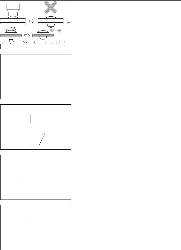
16.REMOVE SLIDE DOOR LOCK REMOTE CONTROL ASSEMBLY
(a)Disconnect the control link.
(b)Attach the rivet cutter to a drill.
(c)Gently and vertically put the drill to the rivet, and cut the
rivet flanges.
NOTICE:
SPrizing the hole with a drill can lead to damage to the rivet hole or breaking the rivet cutter.
STake care as the cut rivet is hot.
w/ Power slide door:
H07402
2001 SIENNA (RM787U)
Author!: |
Date!: |
1698 |
BO-22
BODY - SLIDE DOOR
(d)Even if flange is taken off, continue drilling and push out remaining fragments with the drill.
(e)Remove the slide door lock control assembly.
H02438
Riveter
Mandrel
Riveter
Riveter
HINT:
At the time of reassembly, please refer to the following items.
SApply MP grease to the sliding surface of the slide door lock control assembly.
SUsing an air riveter or hand riveter, install the slide door lock control assembly to the door frame with the rivets.
H02439
NOTICE:
At the time of reassembly, please refer to the following items.
SDo not prize a riveter, as riveter is damaged, it is not tightened and the mandrel is bent.
H02440
SDo not tilt the riveter and disconnect the rivet from the material while handling a riveter, as the materials are not tightened firmly.
H02441
SInstall the rivet while attaching materials, as they are not tightened firmly.
Riveter
H02442
2001 SIENNA (RM787U)
Author!: |
Date!: |
1699 |
BO-8
BODY - FRONT DOOR
BO0S1-03
DISASSEMBLY
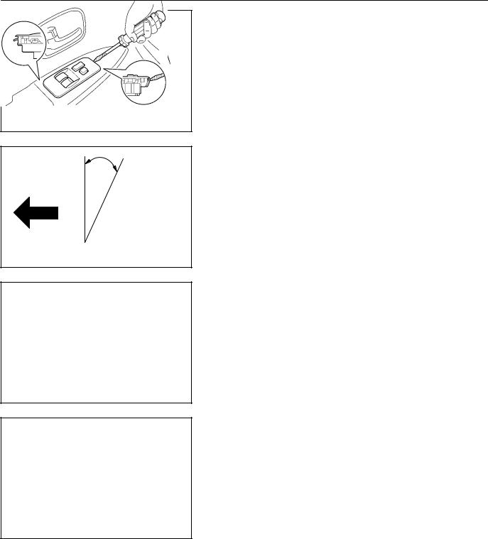
1.w/o Power window:
REMOVE REGULATOR HANDLE
Pull off the snap ring with a shop rag and remove the regulator handle and plate.
BO0020
30°
Front
N03522
HINT:
At the time of reassembly, please refer to the following item. With door window fully closed, install the plate and regulator handle with the snap ring, as shown in the illustration.
2.REMOVE INSIDE HANDLE BEZEL
(a)Remove the screw.
(b)Using a screwdriver, remove the inside handle bezel as
shown in the illustration.
HINT:
Tape the screwdriver tip before use.
H02333
3.w/ Power window:
REMOVE POWER WINDOW SWITCH
(a)Using a screwdriver, remove the power window switch.
HINT:
Tape the screwdriver tip before use.
(b)Disconnect the connector.
4.REMOVE ARMREST
5.REMOVE COURTESY LIGHT
H02334 6. w/o Power window:
REMOVE UPPER ARMREST BASE PANEL
2001 SIENNA (RM787U)
Author!: |
Date!: |
1685 |
BO-9
BODY - FRONT DOOR
: 7 Clips
H02335
N23104
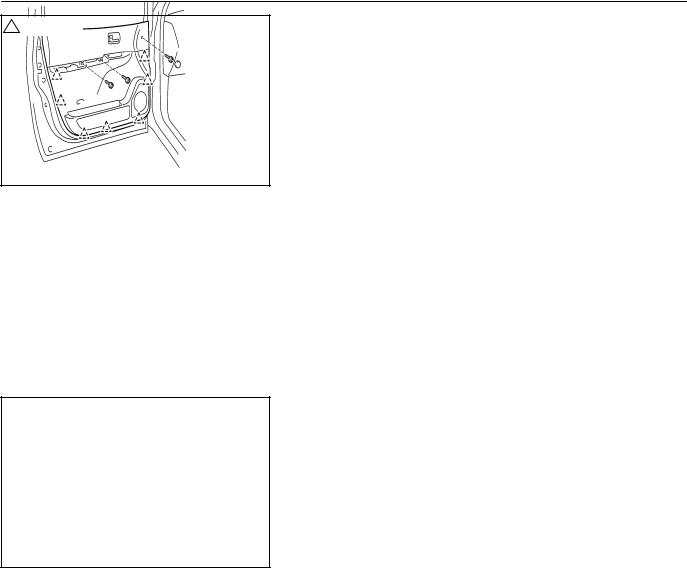
7.REMOVE DOOR TRIM
(a)Remove the cap and screw.
(b)Remove the 2 screws.
(c)Insert a screwdriver between the door and door trim to pry
the trim out.
NOTICE:
Be careful not to damage the door and door trim.
HINT:
Tape the screwdriver tip before use.
(d)Pull the trim upward to remove it.
(e)Remove the inner weatherstrip from the door trim.
8.REMOVE INSIDE HANDLE
(a)Remove the screw.
(b)Disconnect the 2 control links from the inside handle as
shown in the illustration.
9.REMOVE SERVICE HOLE COVER
Remove the 2 grommets and cover.
NOTICE:
At the time of reassembly, please refer to the following item.
Do not block the trim clip sealing with the service hole cover.
HINT:
At the time of reassembly, please refer to the following item. Bring out the connector and 2 links through the service hole cover.
10.REMOVE OUTSIDE REAR VIEW MIRROR
(a)w/ Power remote control mirror:
Disconnect the connector, then remove the clamp.
(b)Remove the 3 bolts and mirror.
Torque: 7.8 N·m (80 kgf·cm, 69 in.·lbf)
11.REMOVE SPEAKER
(a)Remove the 3 screws.
(b)Disconnect the connector.
(c)Remove the speaker.
12.REMOVE DOOR GLASS
(a)Remove the 2 bolts.
Torque: 5.4 N·m (55 kgf·cm, 48 in.·lbf)
(b)Remove the door glass.
2001 SIENNA (RM787U)
Author!: |
Date!: |
1686 |
BO-10
BODY - FRONT DOOR
13.REMOVE OUTER WEATHERSTRIP
Using a scraper, remove the outer weatherstrip as shown in the illustration.
HINT:
Tape the scraper tip before use.
14.REMOVE DOOR GLASS RUN
15.REMOVE LOWER FRAME
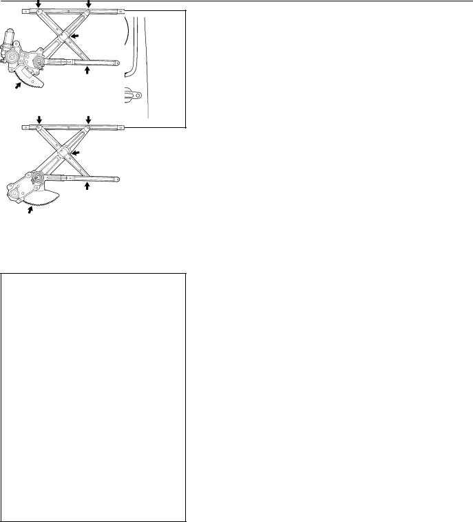
16.REMOVE WINDOW REGULATOR
H02336 (a) w/ Power window:
Disconnect the connector.
w/ Power window:
w/o Power window:
(b)w/ Power window:
Remove the 6 bolts and window regulator.
Torque: 5.4 N·m (55 kgf·cm, 48 in.·lbf)
(c)w/o Power window:
Remove the 5 bolts, nut and window regulator.
Torque: 5.4 N·m (55 kgf·cm, 48 in.·lbf)
HINT:
Remove the regulator through the service hole.
HINT:
At the time of reassembly, please refer to the following item. Apply MP grease to the window regulator.
NOTICE:
At the time of reassembly, please refer to the following item.
Do not apply grease to the spring of the window regulator.
17.w/ Power window (driver’s side): REMOVE WINDOW REGULATOR MOTOR
(a)Place matchmarks on the window regulator motor bracket and regulator gear.
(b)Using a torx wrench, remove the 3 screws and motor.
HINT:
At the time of reassembly, please refer to the following item. Align the matchmarks on the regulator motor bracket and regulator gear.
NOTICE:
If having rotated the motor only, reset the motor
H02337 (See page BE-65 ).
HINT:
Never rotate the motor to the down direction until the complete of the window glass installation.
18.w/ Power window (passenger’s side): REMOVE WINDOW REGULATOR MOTOR
Using a torx wrench, remove the 3 screws and motor.
2001 SIENNA (RM787U)
Author!: |
Date!: |
1687 |
BO-1 1
BODY - FRONT DOOR
19.REMOVE DOOR LOCK
(a)Remove the inside locking link protector.
(b)Disconnect the inside handle opening link.
(c)Using a clip remover, remove the bellcrank and clamp.
H02338
|
(d) Disconnect the locking link assembly. |
|
(e) w/ Power door lock: |
|
Disconnect the connector. |
|
(f) Disconnect the 2 links from outside handle and door lock |
|
cylinder. |
|
(g) Using a torx wrench, remove the 3 screws and door lock. |
|
Torx wrench: T30 (Part No. 09042-00010 or locally |
|
manufactured tool) |
H02339 |
Torque: 4.9 N·m (50 kgf·cm, 43 in.·lbf) |
|
HINT: |
Remove the door lock through the service hole.
HINT:
At the time of reassembly, please refer to the following items.
SApply adhesive to 3 screws.
Part No. 08833-00070, THREE BOND 1324 or equivalent
SApply MP grease to the sliding and rotating parts of the door lock.
H03705
H03952
2001 SIENNA (RM787U)
20.REMOVE OUTSIDE HANDLE WITH DOOR LOCK CYL-
INDER
(a)Disconnect the connector, then remove the clamps.
(b)Remove the cap, 2 bolts and outside handle with door lock cylinder.
Torque: 5.5 N·m (56 kgf·cm, 49 in.·lbf)
(c)Remove the bolt and door lock cylinder from the outside handle.
Torque: 5.5 N·m (56 kgf·cm, 49 in.·lbf)
Author!: |
Date!: |
1688 |
BO-29
BODY - BACK DOOR
BO23Y-01
DISASSEMBLY
1.REMOVE BACK DOOR ASSIST GRIP
(a)Using a screwdriver, open the covers.
HINT:
Tape the screwdriver tip before use.
(b)Remove the 2 screws and assist grip.
H02348
2.REMOVE BACK DOOR PULL STRAP
(a)Using a screwdriver, remove the strap cover.
HINT:
Tape the screwdriver tip before use.
(b)Remove the screw and pull strap.
|
H02349 |
: 5 Clips |
3. REMOVE CENTER GARNISH |
Using a screwdriver, remove the center garnish.
HINT:
Tape the screwdriver tip before use.
H02350
|
|
: 3 Clips |
|
4. |
REMOVE SIDE GARNISH |
|
|
|
|||
|
|
|
|
(a) |
Using a screwdriver, remove the side garnish. |
|
|
|
|
HINT: |
|
|
|
|
|
Tape the screwdriver tip before use. |
|
|
|
|
|
(b) |
Employ the same manner described above to the other |
|
|
|
|
|
side. |
|
|
|
H02351 |
|
|
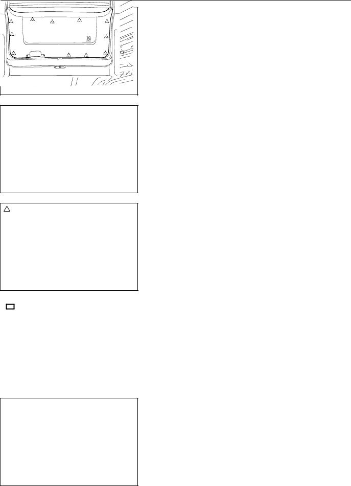
 : 11 Clips
2001 SIENNA (RM787U)
5.REMOVE DOOR TRIM BOARD
(a)Insert a screwdriver between the door and door trim board to pry the door trim board out.
NOTICE:
Be careful not to damage the door and door trim board.
HINT:
Tape the screwdriver tip before use.
(b)Pull the door trim board to remove it.
H02352
Author!: |
Date!: |
1706 |
BO-30
 : Clip
BODY - BACK DOOR
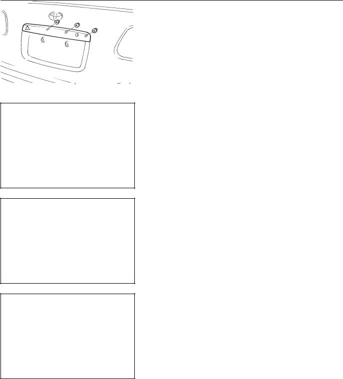
6.REMOVE HIGH-MOUNTED STOP LIGHT
(a)Remove the 2 screws.
(b)Disconnect the connector.
(c)Remove the high-mounted stop light.
7.REMOVE WASHER NOZZLE
8.REMOVE REAR WIPER ARM
Remove the nut, rear wiper arm.
Torque: 5.4 N·m (55 kgf·cm, 48 in.·lbf)
H02368
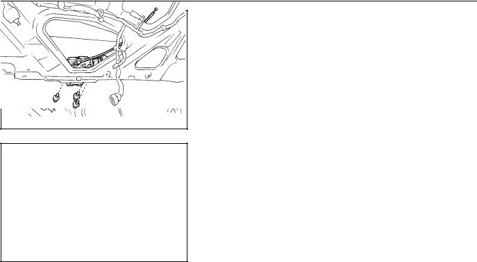
9.REMOVE WIPER MOTOR AND LINK ASSEMBLY
(a)Remove the 3 bolts from the wiper motor.
(b)Remove the 2 bolts and wiper motor and link assembly.
Torque: 5.4 N·m (55 kgf·cm, 48 in.·lbf)
(c)Remove the grommet.
10.REMOVE COMBINATION LIGHTS
H02639
11.REMOVE LICENSE PLATE LIGHT ASSEMBLY
(a)Disconnect the back door control cable from the handle lever.
(b)Disconnect the connector.
(c)Remove the 3 nuts.
(d)Using a screwdriver, remove the license plate light as-
sembly.
HINT:
H02353 Tape the screwdriver tip before use.
(e)Remove the handle lever from the license plate light cover.
(f)Remove the license plate light assembly from the license plate light cover.
2001 SIENNA (RM787U)
Author!: |
Date!: |
1707 |
BO-31
BODY - BACK DOOR
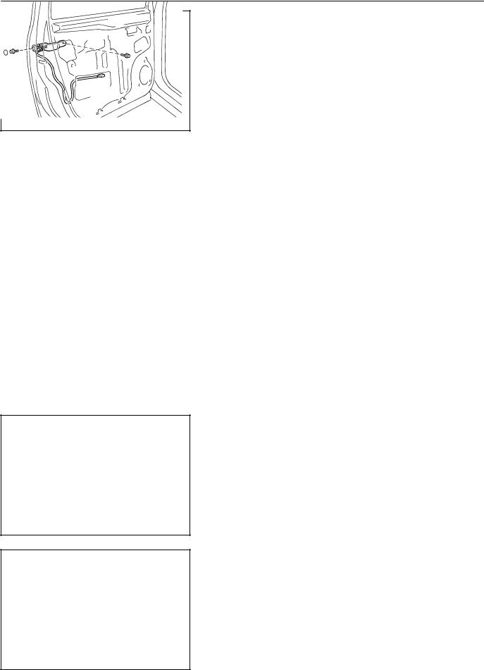
12.REMOVE KEY CYLINDER
(a)Disconnect the back door lock locking link from the key cylinder.
(b)Disconnect the connector.
(c)Remove the 2 bolts and key cylinder.
Torque: 5.5 N·m (56 kgf·cm, 49 in.·lbf)
H02354
13.REMOVE BACK DOOR LOCK
(a)Disconnect the connectors.
(b)Remove the 3 bolts and door lock.
Torque: 7.8 N·m (80 kgf·cm, 69 in.·lbf)
H02355
2001 SIENNA (RM787U)
Author!: |
Date!: |
1708 |
BO-7
BODY - FRONT DOOR
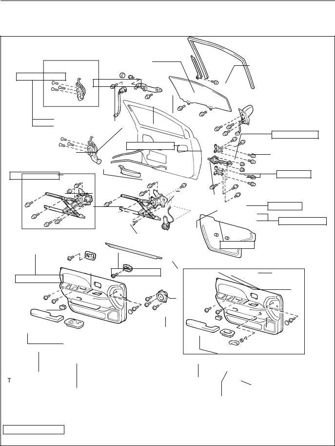
FRONT DOOR
COMPONENTS |
|
|
|
|
BO0S0-03 |
|
|
|
|
|
|
||
|
|
|
Lower Frame |
|
Door Glass Run |
|
|
|
|
|
|
|
|
L 4.9 (50, 43 in.·lbf) |
5.5 (56, 49 in.·lbf) |
|
|
|
||
|
|
|
|
|||
|
|
|
Door Glass |
|
|
|
w/o Power door |
|
Outside Handle |
|
|
|
|
lock: |
|
|
|
|
|
|
|
|
|
|
|
7.8 (80, 69 in.·lbf) |
|
Door Lock Cylinder |
|
5.4 (55, 48 in.·lbf) |
|
Outside Rear |
|
|
|
|
Door Check |
|
|||
|
Locking Link Assembly |
|
View Mirror |
|
||
L 4.9 (50, 43 in.·lbf) |
|
25 (260, 19) |
|
|||
|
|
|
|
|
||
Door Lock |
|
|
|
Inside Handle |
|
|
Inside Locking Link Protector |
|
|
Opening Link |
25 (260, 19) |
|
|
|
|
|
|
|||
w/o Power window: |
Window |
|
5.5 (56, 49 in.·lbf) |
|||
|
|
Regulator |
|
|||
|
|
Door Hinge |
|
|
||
|
|
|
|
|
|
|
|
|
|
|
30 (306, 22) |
|
|
Inside Handle Bezel |
5.4 (55, 48 in.·lbf) |
Window |
Service Hole Cover |
|||
5.4 (55, 48 in.·lbf) |
|
|
|
Regulator |
|
|
|
|
Inside Handle |
Motor |
Grommet |
||
|
|
Outer Weatherstrip |
||||
|
|
|
|
|||
|
|
|
|
|
|
|
Door Trim |
|
|
|
w/o Power window: |
Door Trim |
|
|
|
|
Speaker |
|
||
Courtesy Light |
|
|
|
Courtesy |
|
|
|
|
|
Light |
|
|
|
|
|
|
|
|
|
|
Armrest |
|
|
|
Armrest |
|
|
|
|
|
|
Regulator Handle |
|
|
Power Window Switch |
|
|
||||
Upper Armrest |
|
|
||||
|
|
|
|
|
|
|
|
|
|
|
Base Panel |
|
|
N·m (kgf·cm, ft·lbf) |
: Specified torque |
|
|
|
||
L Precoated part |
|
|
|
|
|
H15885 |
2001 SIENNA (RM787U) |
|
|
|
|
|
|
|
|
|
|
Author!: |
Date!: |
1684 |
BO-5
BODY - REAR BUMPER
REAR BUMPER
BO0RY-02
COMPONENTS
Rear Bumper Arm
31 (320, 23)
31 (320, 23)
Side Mounting Bracket
No.3 Side Bracket
Rear Bumper Reinforcement
Energy Absorber
No.2 Side Bracket
6.8 (70, 61 in.·lbf)
Rear Bumper Cover
N·m (kgf·cm, ft·lbf) : Specified torque
H02346
2001 SIENNA (RM787U)
Author!: |
Date!: |
1682 |

BO-47
BODY - BODY OUTSIDE MOULDING
BODY OUTSIDE MOULDING
BO0SL-03
COMPONENTS
Outside Quarter
Moulding
Hole Plug
Slide Door
Outside Moulding
|
Front Door |
Front Fender |
|
Outside Moulding |
Outside Moulding |
Back Door Lower
Outside Moulding
H15781
2001 SIENNA (RM787U)
Author!: |
Date!: |
1724 |

BO-35
BODY - FRONT WIPER AND WASHER
FRONT WIPER AND WASHER
COMPONENTS |
|
|
BO0SD-02 |
|
|
|
|
||
|
|
Wiper Arm |
|
|
|
|
Cap |
|
|
|
|
20 (205, 15) |
|
|
|
|
|
Cap |
|
RH Cowl Top |
|
|
20 (205, 15) |
|
Ventilator Louver |
|
Washer Nozzle |
LH Cowl Top |
|
|
|
|
|
|
|
|
|
Ventilator Louver |
|
Hood to Cowl |
|
|
|
|
Top Seal |
|
|
|
|
7.8 (80, 69 in.·lbf) |
|
Cowl Panel |
|
|
|
|
|
Hole Cover |
|
|
|
5.5 (56, 49 in.·lbf) |
|
|
|
|
Outer Front Cowl |
7.4 (75, 65 in.·lbf) |
|
|
|
Top Panel |
||
No.1 Cowl Water |
7.4 (75, 65 in.·lbf) |
|
|
|
Wiper Link |
|
|
||
Extract Hose |
|
|
|
|
|
|
|
|
|
|
|
|
No.2 Cowl Water |
|
|
|
7.4 (75, 65 in.·lbf) |
Extract Hose |
|
|
|
|
|
|
|
|
Wiper Motor |
|
|
N·m (kgf·cm, ft·lbf) |
: Specified torque |
|
H02358 |
|
|
|
|
|
|
2001 SIENNA (RM787U) |
|
|
|
|
|
|
Author!: |
Date!: |
1712 |

BO-28
BODY - BACK DOOR
BACK DOOR
COMPONENTS |
|
|
BO0S9-02 |
|
|
|
|
||
|
|
Wiper Arm |
|
|
|
Back Door Hinge |
|
|
|
19 (195, 14) |
|
|
5.4 (55, 48 in.·lbf) |
|
|
|
|
|
|
|
|
5.4 (55, 48 in.·lbf) |
|
|
|
19 (195, 14) |
Grommet |
|
|
Center Garnish |
|
|
Wiper Motor and |
|
|
|
Link Assembly |
|
|
|
|
Washer Nozzle |
|
|
|
|
|
17 (175, 13) |
|
Side Garnish |
High-mounted |
|
Back Door Stay |
|
|
|
|
||
|
Stop Light |
|
|
|
Door Trim Board |
|
|
22 (225, 16) |
|
|
|
|
Stopper Cushion |
|
|
|
|
5.5 (56, 49 in.·lbf) |
|
|
|
Lower Stopper |
Key Cylinder |
|
|
Back Door Assist Grip |
|
||
|
License Plate Light |
|||
Strap Cover |
|
|||
|
|
|
Cover |
|
|
Control Link |
License Plate |
Light |
|
Back Door Pull Strap |
|
Assembly |
|
|
|
|
|
Handle Lever |
|
|
Back Door Lock |
x 3 |
|
|
|
7.8 (80, 69 in.·lbf) |
|
|
|
|
|
|
|
|
|
|
|
Rear Combination Light |
|
|
|
|
Back Door Scuff Plate |
|
|
|
|
11 (115, 8) |
|
|
Rear Combination Light |
Door Lock Striker |
|
|
|
|
|
|
|
N·m (kgf·cm, ft·lbf) |
: Specified torque |
|
|
H02356 |
|
|
|
|
|
2001 SIENNA (RM787U) |
|
|
|
|
|
|
Author!: |
Date!: |
1705 |

BO-14
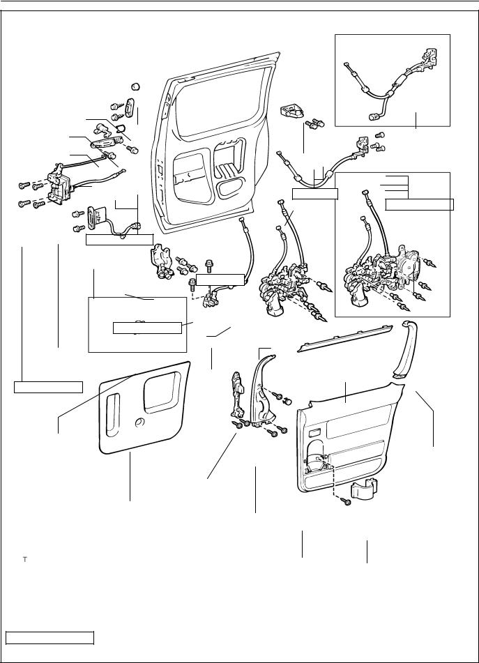
BODY - SLIDE DOOR
SLIDE DOOR
BO0S3-04
COMPONENTS
Upper Rail Cushion
Male Stopper
Front Lock
Striker
Center Quarter
Trim Cover
23 (230, 17)
Quarter Trim |
Speaker Grille |
||
Cover |
|
|
43 (440, 32) |
|
|
|
|
Rear Lock Striker Slide Door Control
Slide Door Female Junction
Scuff Plate
Slide Door
 Rear No.1 Seat
Outer Belt
Center Rail Garnish
Quarter Trim Panel
w/ Power slide door:
Power Slide Door Drive Unit
w/ LH power slide door:
Power Slide Door Drive Unit
|
|
|
|
|
Center Rail |
|
|
|
|
w/ Power slide door: |
|
|
w/ Power |
|
|
||
|
|
|
slide door: |
|
|
|||
|
Rear Seal Grommet |
|
|
|
|
|||
|
|
|
|
|
|
|
||
|
|
x 6 |
|
|
|
|
|
|
9.8 (100, 7) |
|
|
|
|
|
|
||
|
Center Rail |
|
|
|
|
|
|
|
|
|
|
|
|
|
|
||
|
Protector |
|
|
|
|
|
|
|
|
|
|
9.8 (100, 7) |
|
|
|
|
|
|
|
Center Roller |
|
|
Lower Step Plate |
|||
|
|
|
|
|||||
Back Door Scuff Plate |
Open Striker |
|
|
|||||
|
|
|
|
|
7.0 (71, 62 in.·lbf) |
|||
N·m (kgf·cm, ft·lbf) |
: Specified torque |
Rear Door Check Cover |
H15875
2001 SIENNA (RM787U)
Author!: |
Date!: |
1691 |
|
BODY |
- |
SLIDE DOOR |
BO-15 |
|
|
|
|
|||
|
|
|
|
w/ Power slide door: |
|
|
Cushion |
|
Upper Roller |
|
|
Female Stopper |
|
|
|
|
|
Retainer |
|
|
|
Slide Door |
|
Key Cylinder |
|
|
|
Lock |
|
|
|
|
Assembly |
|
|
Outside Handle |
|
|
13 (130, 9) |
|
|
|
|
|
L 4.9 (50, 43 in.·lbf) |
|
|
|
|
|
|
|
|
|
|
|
Slide Door Lock |
w/ Power slide door: |
|
|
5.5 (56, 49 in.·lbf) |
|
Slide Door Lock |
|
|
|
|
Assembly |
|
||
|
|
|
|
||
|
|
|
|
Remote Control |
|
|
30 (310, 22) |
|
|
|
|
|
Lower Roller |
|
|
|
|
Slide Door Control |
|
|
|
|
|
Male Junction |
|
|
|
|
|
|
8.0 (82, 71 in.·lbf) |
|
|
|
|
Slide Door |
w/ Power slide door: |
|
|
|
|
|
|
Slide Door Lock |
|
|
|
Front Lock |
Slide Door |
|
|
||
|
Remote Control |
|
|
||
L 4.9 (50, 43 in.·lbf) |
Full Open |
|
|
|
|
|
Stop Lock |
|
Upper No.1 |
|
|
|
|
|
|
||
|
|
|
Trim Cover |
|
|
Slide Door Lock |
|
|
|
Upper No.2 |
|
Remote Control |
|
|
|
||
|
|
|
|
Trim Cover |
|
|
Inside Handle |
|
|
|
|
Service Hole Cover |
|
|
|
|
|
|
Window Garnish |
|
|
||
|
|
|
Door Trim |
Cup Holder |
|
|
|
|
|
|
|
N·m (kgf·cm, ft·lbf) |
: Specified torque |
|
|
|
|
L Precoated Part |
|
|
|
|
H07337 |
2001 SIENNA (RM787U) |
|
|
|
|
|
|
|
|
Author!: |
Date!: |
1692 |

BO-41
BODY - REAR WIPER AND WASHER
REAR WIPER AND WASHER
COMPONENTS |
|
|
BO0SH-02 |
|
|
|
|
||
|
|
Washer Nozzle |
|
|
|
|
|
Side Garnish |
|
|
|
Center Garnish |
|
|
|
Side Garnish |
|
|
|
|
|
|
Door Trim Board |
|
|
|
|
Back Door Assist Grip |
|
|
|
|
5.4 (55, 48 in.·lbf) |
|
|
Strap Cover |
|
|
|
|
Back Door Pull Strap |
Wiper Arm |
|
|
|
|
5.4 (55, 48 in.·lbf) |
|
|
|
|
Wiper Motor and Link |
|
|
|
|
Assembly |
5.4 (55, 48 in.·lbf) |
|
N·m (kgf·cm, ft·lbf) : Specified torque |
|
|
||
|
|
H02638 |
||
|
|
|
|
|
2001 SIENNA |
(RM787U) |
|
|
|
|
|
Author!: |
Date!: |
1718 |
BO-4
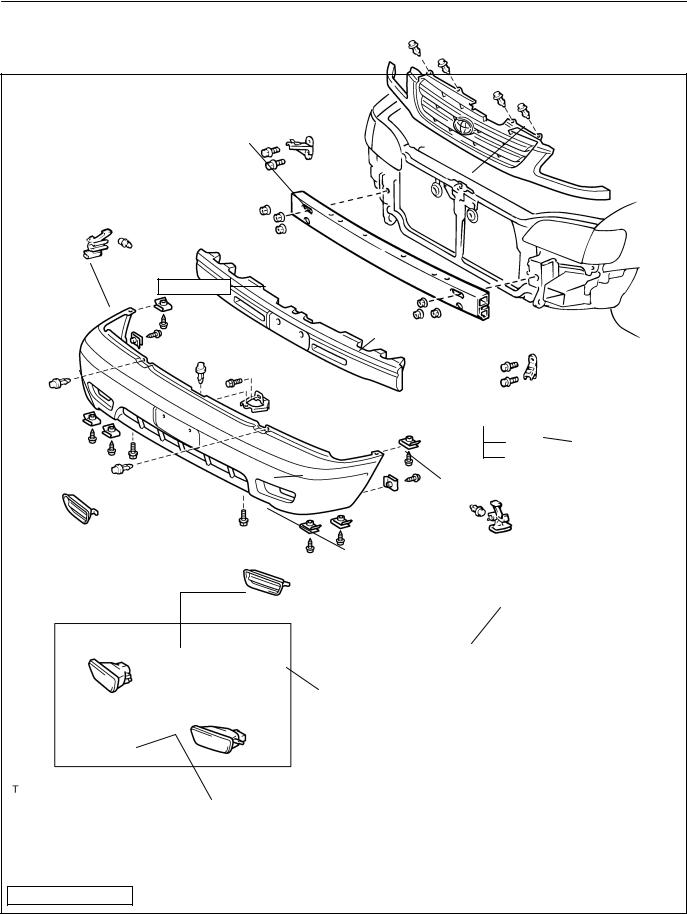
BODY - FRONT BUMPER
FRONT BUMPER
BO0RX-03
COMPONENTS
Radiator Grille
Side Mounting Bracket
Side Support
31 (320, 23)
Front Bumper Cover |
Front Bumper |
|||||
Reinforcement |
||||||
|
|
|
|
|
|
|
|
5.4 (55, 48 in.·lbf) |
|
|
5.4 (55, 48 in.·lbf) |
|
|
|
|
|
|
|
|
Side Mounting |
|
|
|
|
|
|
Bracket |
|
|
|
||||
|
|
|
|
Center Stay |
||
|
|
|
|
|
Energy Absorber |
|
7.6 (78, 68 in.·lbf) |
Side Support |
Hole Cover
w/ Fog light:
Fog Light
N·m (kgf·cm, ft·lbf) : Specified torque
H15795
2001 SIENNA (RM787U)
Author!: |
Date!: |
1681 |
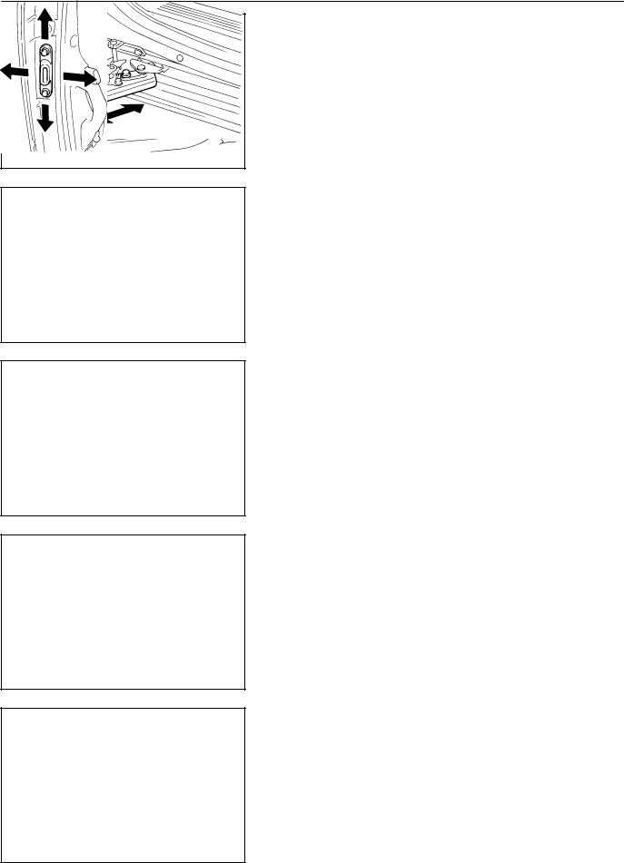
BO-23
BODY - SLIDE DOOR
BO2JD-01
ADJUSTMENT
1.ADJUST REAR SIDE OF DOOR IN FORWARD/REARWARD AND VERTICAL DIRECTIONS
Loosen the center hinge mounting bolts to adjust.
Torque: 30 N·m (310 kgf·cm, 22 ft·lbf)
H02627
2. ADJUST DOOR IN VERTICAL DIRECTION
Loosen the lower roller mounting bolts to adjust.
Torque: 30 N·m (310 kgf·cm, 22 ft·lbf)
H02628
3.ADJUST DOOR IN FORWARD/REARWARD DIRECTION
Loosen the upper roller mounting bolts to adjust.
Torque: 13 N·m (130 kgf·cm, 9 ft·lbf)
H02629
4. ADJUST DOOR IN LEFT/RIGHT DIRECTION
Loosen the lower roller base mounting bolts to adjust.
H02630
5.ADJUST DOWN FEMALE STOPPER
Loosen the down female stopper mounting bolts to adjust.
H02631
2001 SIENNA (RM787U)
Author!: |
Date!: |
1700 |

BO-24
BODY - SLIDE DOOR
6.ADJUST FRONT LOCK STRIKER
(a)Check that the door fit and door lock linkage are adjusted correctly.
(b)Loosen the striker mounting screw.
Torque: 23 N·m (230 kgf·cm, 17 ft·lbf)
(c)Using a plastic hammer, tap the striker to adjust.
H02632
7.ADJUST REAR LOCK STRIKER
(a)Check that the door fit and door lock linkage are adjusted correctly.
(b)Loosen the striker mounting screw.
Torque: 23 N·m (230 kgf·cm, 17 ft·lbf)
(c)Using a plastic hammer, tap the striker to adjust.
H02633
8.ADJUST CONTROL CABLE TENSION
(a)Pull on the rear side cable to provide temporary tension and move roller hinge forward to front of the center rail.
H07346
(b)Open the door 100 mm (3.94 in.).
H11101
Stopper Window
Adjusting Bolt
Rib |
H11102 |
2001 SIENNA (RM787U)
(c)Using a socket wrench, rotate the adjusting bolt clockwise
until hole appears in stopper window on the power slide door drive unit. Then insert a screwdriver to hole.
HINT:
On the drum viewed through the stopper window, there is one part where a rib cannot be seen at all as shown in the illustration.
Author!: |
Date!: |
1701 |
 Loading...