


 Loading...
IN-1
INTRODUCTION - HOW TO USE THIS MANUAL
HOW TO USE THIS MANUAL
IN00U-36
GENERAL INFORMATION
1.INDEX
An INDEX is provided on the first page of each section to guide you to the item to be repaired. To assist you in finding your way through the manual, the section title and major heading are given at the top of every page.
2.PRECAUTION
At the beginning of each section, a PRECAUTION is given that pertains to all repair operations contained in that section.
Read these precautions before starting any repair task.
3.TROUBLESHOOTING
TROUBLESHOOTING tables are included for each system to help you diagnose the problem and find the cause. The fundamentals of how to proceed with troubleshooting are described on page IN-16 .
Be sure to read this before performing troubleshooting.
4.PREPARATION
Preparation lists the SST (Special Service Tools), recommended tools, equipment, lubricant and SSM (Special Service Materials) which should be prepared before beginning the operation and explains the purpose of each one.
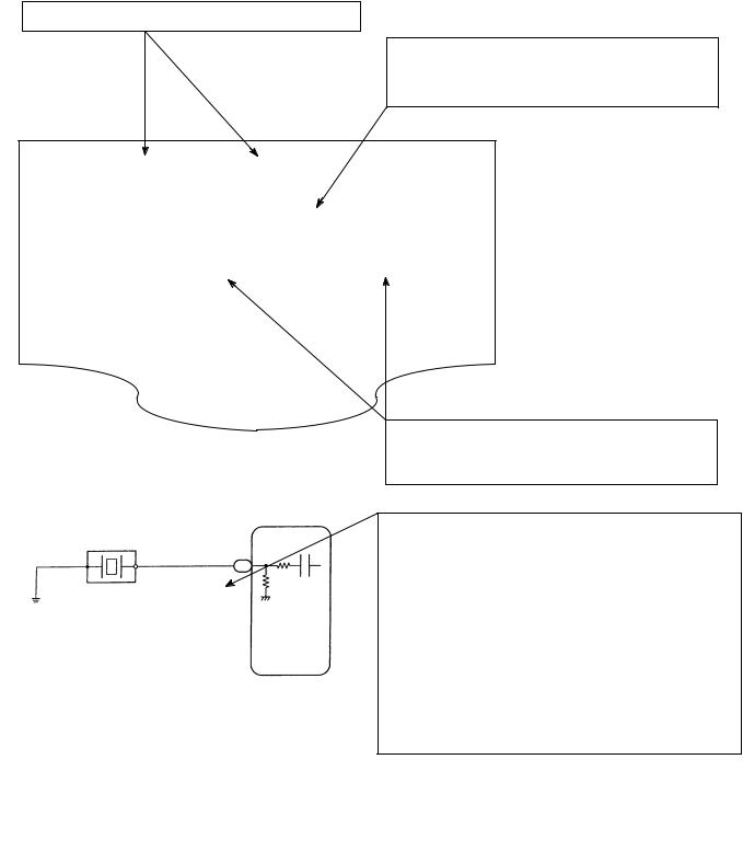
5.REPAIR PROCEDURES
Most repair operations begin with an overview illustration. It identifies the components and shows how the parts fit together.
Example:
|
|
|
|
|
|
|
|
Filler Cap |
|
|
|
|
|
|
|
|||||||
|
|
|
|
|
|
|
|
Float |
|
|
Clevis Pin |
|
|
|||||||||
|
|
|
|
|
|
|
|
Reservoir |
|
Gasket |
|
|
Clip |
|||||||||
|
|
|
|
|
|
|
|
Boot |
|
|
|
|
|
|||||||||
|
|
|
|
|
|
|
|
Grommet |
|
|
|
|
|
|||||||||
|
|
|
|
|
|
|
|
|
|
|
|
|
|
|
||||||||
|
|
|
|
|
|
|
|
|
|
|
|
|
|
|
||||||||
|
|
|
|
|
|
|
|
|
|
|
|
|
|
|
|
|
|
|
|
|
|
|
|
|
|
|
|
|
|
|
|
|
|
|
|
|
|
|
|
|
|
|
|
|
|
|
|
|
|
|
|
|
|
|
|
|
|
|
|
|
|
|
|
|
|
|
|
|
|
Slotted Spring Pin |
|
|
|
|
|
|
|
|
|
|
|
|
|
|
|||||||
|
|
|
12 (120, 9) |
|
|
|
|
|
|
|
|
|
|
|
||||||||
|
|
|
|
|
|
|
|
|||||||||||||||
|
|
|
|
|
|
|
|
|
|
|
|
|
|
|
|
|
|
|
|
|
|
|
|
|
|
|
|
|
|
|
|
|
|
|
|
|
|
|
|
|
|
Clevis |
|
|
|
|
|
|
|
|
|
|
|
|
|
|
|
|
|
|
|
|
|
|||||
|
15 (155, 11) |
|
|
|
|
|
|
|
|
|
|
|
|
|
|
|
|
|
|
|
|
|
|
|
|
|
|
|
|
|
|
|
|
Snap Ring |
|
|
|
|
|||||||
|
|
|
|
|
|
|
|
|
|
|
|
|
|
|
|
|
|
|||||
|
|
|
|
|
|
|
|
|
|
|
|
|
|
|
|
|
|
|||||
|
|
|
|
|
|
|
|
|
|
|
|
|
||||||||||
|
|
|
|
|
|
|
|
|
|
|
|
|
Washer |
|
|
Lock Nut |
|
|
||||
|
|
|
|
|
|
|
|
|
|
|
|
Push Rod |
|
|
|
|
|
|
|
|||
|
|
|
|
|
|
|
|
|
|
Piston |
|
|
|
|
|
|
|
|||||
|
|
|
|
|
|
|
|
|
|
|
|
|
|
|
|
|
|
|
|
|
|
|
|
|
|
|
|
|
|
|
|
|
|
|
|
|
|
|
|
|
|
|
|
|
|
|
|
|
|
|
Cylinder |
|
|
|
|
|
|
|
|
|
|
|
|
|
|
|
||
|
|
|
|
|
|
|
|
|
|
|
|
|
||||||||||
|
N´m (kgf´cm, ft´lbf) |
: Specified torque |
|
|
|
|
|
|
|
|||||||||||||
|
Non-reusable part |
|
|
|
|
|
|
|
|
|
|
|
|
|
|
N17080 |
||||||
|
|
|
|
|
|
|
|
|
|
|
|
|
|
|
|
|
|
|
|
|
|
|
|
|
|
|
|
|
|
|
|
|
|
|
|
|
|
|
|
|
|
|
|
|
|
1996 TERCEL (RM440U)
Author : |
Date : |
1 |
IN-2
INTRODUCTION - HOW TO USE THIS MANUAL
The procedures are presented in a step-by-step format:
The illustration shows what to do and where to do it.
The task heading tells what to do.
The detailed text tells how to perform the task and gives other information such as specifications and warnings.
Example:
Illustration: what to do and where
Task heading : what to do
21. CHECK PISTON STROKE OF OVERDRIVE BRAKE
(a)Place SST and a dial indicator onto the overdrive brake piston as shown in the illustration.
SST 09350-30020 (09350-06120)
Set part No. |
Component part No. |
Detailed text : how to do task
(b)Measure the stroke applying and releasing the compressed air (392 785 kPa, 4 8 kgf/cm2 or 57 114 psi) as shown in the illustration.
Piston stroke: 1.40 1.70 mm (0.0551 0.0669 in.)
Specification
This format provides the experienced technician with a FAST TRACK to the information needed. The upper case task heading can be read at a glance when necessary, and the text below it provides detailed information. Important specifications and warnings always stand out in bold type.
6.REFERENCES
References have been kept to a minimum. However, when they are required you are given the page to refer to.
7.SPECIFICATIONS
Specifications are presented in bold type throughout the text where needed. You never have to leave the procedure to look up your specifications. They are also found in Service Specifications section for quick reference.
8. |
CAUTIONS, NOTICES, HINTS: |
|
CAUTIONS are presented in bold type, and indicate there is a possibility of injury to you or other |
|
people. |
|
NOTICES are also presented in bold type, and indicate the possibility of damage to the components |
|
being repaired. |
|
HINTS are separated from the text but do not appear in bold. They provide additional information to |
|
help you perform the repair efficiently. |
9. |
SI UNIT |
The UNITS given in this manual are primarily expressed according to the SI UNIT (International System of Unit), and alternately expressed in the metric system and in the English System.
Example:
Torque: 30 N´m (310 kgf´cm, 22 ft´lbf)
1996 TERCEL (RM440U)
Author : |
Date : |
2 |
IN-3
INTRODUCTION - IDENTIFICATION INFORMATION
IDENTIFICATION INFORMATION
IN07B-01
VEHICLE IDENTIFICATION AND ENGINE SERIAL NUMBER
A
B
N13014
1.VEHICLE IDENTIFICATION NUMBER
The vehicle identification number is stamped on the vehicle identification number plate and the certification label, as shown in the illustration.
A:Vehicle Identification Number Plate
B:Certification Label
2.ENGINE SERIAL NUMBER
The engine serial number is stamped on the engine block, as shown in the illustration.
P01214
1996 TERCEL (RM440U)
Author : |
Date : |
3 |
IN-4
INTRODUCTION - REPAIR INSTRUCTIONS
FI1066
Seal Lock Adhesive
Z11554
1996 TERCEL (RM440U)
REPAIR INSTRUCTIONS
IN0CO-12
GENERAL INFORMATION
BASIC REPAIR HINT
(a)Use fender, seat and floor covers to keep the vehicle clean and prevent damage.
(b)During disassembly, keep parts in the appropriate order to facilitate reassembly.
(c)Installation and removal of battery terminal:
(1)Before performing electrical work, disconnect the negative (-) terminal cable from the battery.
(2)If it is necessary to disconnect the battery for inspection or repair, first disconnect the negative (-) terminal cable.
(3)When disconnecting the terminal cable, to prevent damage to battery terminal, loosen the cable nut and raise the cable straight up without twisting or prying it.
(4)Clean the battery terminals and cable ends with a clean shop rag. Do not scrape them with a file or other abrasive objects.
(5)Install the cable ends to the battery terminals after loosening the nut, and tighten the nut after installation. Do not use a hammer to tap the cable ends onto the terminals.
(6)Be sure the cover for the positive (+) terminal is properly in place.
(d)Check hose and wiring connectors to make sure that they are connected securely and correctly.
(e)Non-reusable parts
(1)Always replace cotter pins, gaskets, O-rings, oil seals, etc. with new ones.
(2)Non-reusable parts are indicated in the component illustrations by the º º symbol.
(f)Precoated parts
Precoated parts are bolts, nuts, etc. that are coated with a seal lock adhesive at the factory.
(1)If a precoated part is retightened, loosened or caused to move in any way, it must be recoated with the specified adhesive.
(2)When reusing precoated parts, clean off the old adhesive and dry with compressed air. Then apply the specified seal lock adhesive to the bolt, nut or threads.
Author : |
Date : |
4 |
IN-5
INTRODUCTION - REPAIR INSTRUCTIONS
(3)Precoated parts are indicated in the component illustrations by the º º symbol.
(g)When necessary, use a sealer on gaskets to prevent leaks.
(h)Carefully observe all specifications for bolt tightening torques. Always use a torque wrench.
(i)Use of special service tools (SST) and special service materials (SSM) may be required, depending on the nature of the repair. Be sure to use SST and SSM where specified and follow the proper work procedure. A list of SST and SSM can be found in Preparation section in this manual.
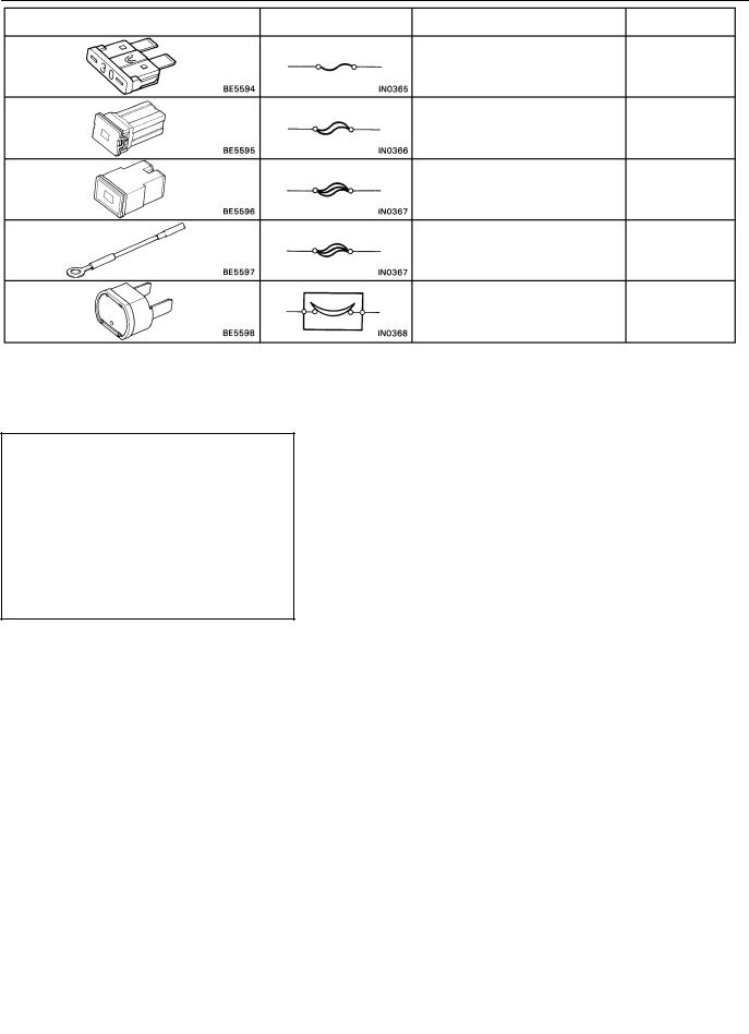
Medium Current Fuse and High Current Fuse |
(j) When replacing fuses, be sure the new fuse has the cor- |
|
rect amperage rating. DO NOT exceed the rating or use |
||
Equal Amperage Rating |
||
|
one with a lower rating. |
BE1367
Illustration |
Symbol |
Part Name |
Abbreviation |
|
|
FUSE |
FUSE |
|
|
MEDIUM CURRENT FUSE |
M-FUSE |
|
|
HIGH CURRENT FUSE |
H-FUSE |
|
|
FUSIBLE LINK |
FL |
|
|
CIRCUIT BREAKER |
CB |
|
|
|
V00076 |
1996 TERCEL (RM440U) |
|
|
|
Author : |
Date : |
5 |
IN-6
INTRODUCTION - REPAIR INSTRUCTIONS
(k)Care must be taken when jacking up and supporting the vehicle. Be sure to lift and support the vehicle at the proper locations (See page IN-8 ).
Cancel the parking brake on the level place and shift the transmission in Neutral (or N position).
When jacking up the front wheels of the vehicle at first place stoppers behind the rear wheels.
When jacking up the rear wheels of the vehicle at first place stoppers before the front wheels.
When either the front or rear wheels only should be jacked up, set rigid racks and place stoppers in front and behind the other wheels on the ground.
After the vehicle is jacked up, be sure to support it on rigid racks . It is extremely dangerous to do any work on a vehicle raised on a jack alone, even for a small job that can be finished quickly.
(l)Observe the following precautions to avoid damage to the
following parts:
(1)Do not open the cover or case of the ECU unless absolutely necessary. (If the IC terminals are touched, the IC may be destroyed by static electricity.)
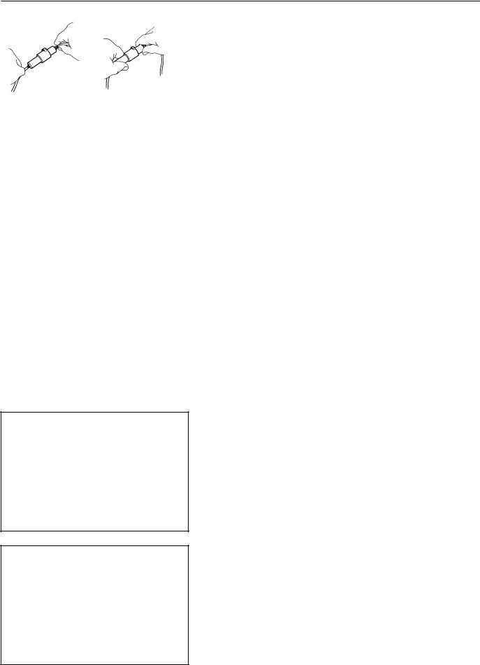
|
|
(2) To disconnect vacuum hoses, pull off the end, not |
WRONG |
CORRECT |
the middle of the hose. |
IN0253
WRONG CORRECT
IN0252
1996 TERCEL (RM440U)
(3)To pull apart electrical connectors, pull on the connector itself, not the wires.
(4)Be careful not to drop electrical components, such as sensors or relays. If they are dropped on a hard floor, they should be replaced and not reused.
(5)When steam cleaning an engine, protect the electronic components, air filter and emission-related components from water.
(6)Never use an impact wrench to remove or install temperature switches or temperature sensors.
Author : |
Date : |
6 |
IN-7
INTRODUCTION - REPAIR INSTRUCTIONS
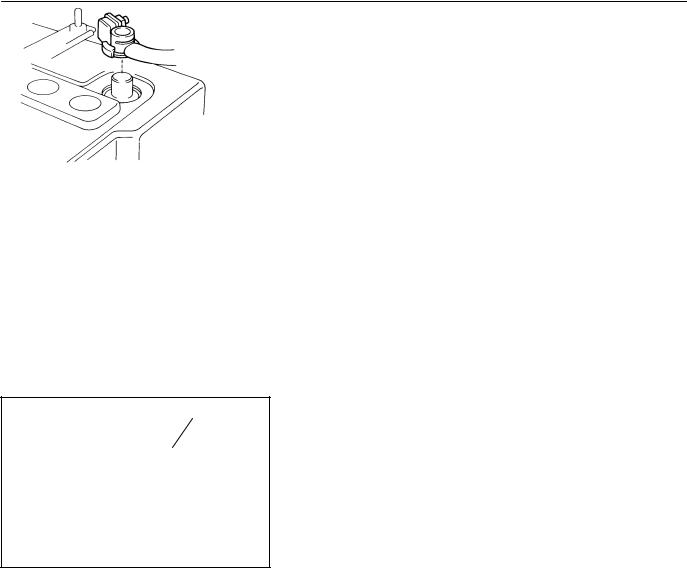
(7)When checking continuity at the wire connector, insert the tester probe carefully to prevent terminals from bending.
(8)When using a vacuum gauge, never force the hose onto a connector that is too large. Use a step-down adapter for adjustment. Once the hose has been stretched, it may leak air.
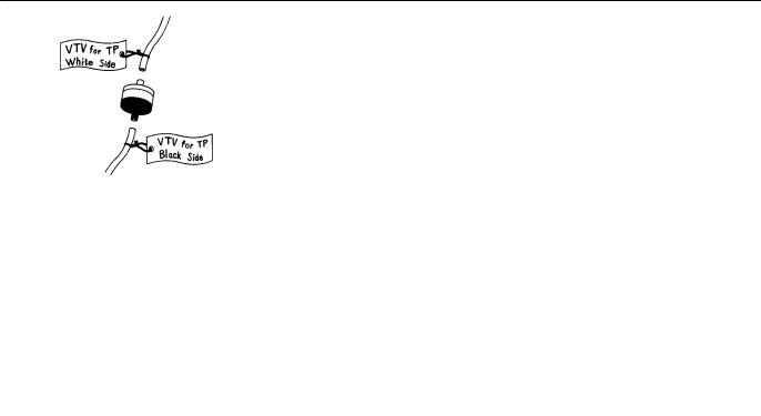
Example |
(m) Installation and removal of vacuum hose: |
|
(1) When disconnecting vacuum hoses, use tags to |
||
|
||
|
identify how they should be reconnected to. |
|
|
(2) After completing a job, double check that the vacu- |
|
|
um hoses are properly connected. A label under the |
|
|
hood shows the proper layout. |
|
|
(n) Unless otherwise stated, all resistance is measured at an |
|
|
ambient temperature of 20°C (68°F). Because the resis- |
|
IN0002 |
tance may be outside specifications if measured at high |
|
|
temperatures immediately after the vehicle has been run- |
|
|
||
|
ning, measurement should be made when the engine has |
|
|
cooled down. |
1996 TERCEL (RM440U)
Author : |
Date : |
7 |

IN-8
INTRODUCTION - REPAIR INSTRUCTIONS
REPAIR INSTRUCTIONS
IN0II-01
VEHICLE LIFT AND SUPPORT LOCATIONS
Front
JACK POSITION |
|
Front |
Front crossmember |
Rear |
Rear axle beam |
CAUTION:
Before jacking-up the front and rear, make sure the car is not carrying any extra weight.
PANTOGRAPH JACK POSITION
SUPPORT POSITION
Safety stand and swing arm type lift
Z14535
1996 TERCEL (RM440U)
IN-9
INTRODUCTION - FOR ALL OF VEHICLES
FOR ALL OF VEHICLES
IN07J-05
PRECAUTION
1.FOR VEHICLES EQUIPPED WITH SRS AIRBAG AND SEAT BELT PRETENSIONER
Negative Cable
BO4111
(a)The TERCEL is equipped with an SRS (Supplemental Restraint System), such as the driver airbag and front passenger airbag.
Failure to carry out service operations in the correct sequence could cause the supplemental restraint system to unexpectedly deploy during servicing, possibly leading to a serious accident.
Further, if a mistake is made in servicing the supplemental restraint system, it is possible the SRS may fail to operate when required. Before servicing (including removal or installation of parts, inspection or replacement), be sure to read the following items carefully, then follow the correct procedure described in this manual.
(b)GENERAL NOTICE
(1)Malfunction symptoms of the supplemental restraint system are difficult to confirm, so the diagnostic trouble codes become the most important source of information when troubleshooting. When troubleshooting the supplemental restraint system, always inspect the diagnostic trouble codes before disconnecting the negative (-) terminal cable from the battery (See page DI-148 ).
(2)Work must be started after 90 seconds from the time the ignition switch is turned to the ºLOCKº position and the negative (-) terminal cable is disconnected from the battery.
(The supplemental restraint system is equipped with a back-up power source so that if work is started within 90 seconds of disconnecting the negative (-) terminal cable from the battery, the SRS may deploy.)
When the negative (-) terminal cable is disconnected from the battery, memory of the clock and audio systems will be cancelled. So before starting work, make a record of the contents memorized by the each memory system. Then when work is finished, reset the clock and audio systems as before. To avoid erasing the memory of each memory system, never use a back-up power supply from another battery.
1996 TERCEL (RM440U)
Author : |
Date : |
9 |
IN-10
INTRODUCTION - FOR ALL OF VEHICLES
(3)Even in cases of a minor collision where the SRS does not deploy, the steering wheel pad (See page RS-9 ) and front passenger airbag assembly (See page RS-22 ) should be inspected.
(4)Never use SRS parts from another vehicle. When replacing parts, replace them with new parts.
(5)Before repairs, remove the airbag sensor if shocks are likely to be attached to the sensor during repairs.
(6)Never disassemble and repair the airbag sensor assembly, steering wheel pad or front passenger airbag.
(7)If the airbag sensor assembly, steering wheel pad or front passenger airbag have been dropped, or if there are cracks, dents or other defects in the case, bracket or connector, replace them with new ones.
(8)Do not directly expose the airbag sensor assembly, steering wheel pad or front passenger airbag to hot air or flames.
(9)Use a volt/ohmmeter with high impedance (10 kΩ/V minimum) for troubleshooting of the electrical circuit.
(10)Information labels are attached to the periphery of the SRS components. Follow the instructions on the notices.
(11)After work is completed, check the SRS warning light for the supplemental restraint system (See page DI-148 ).
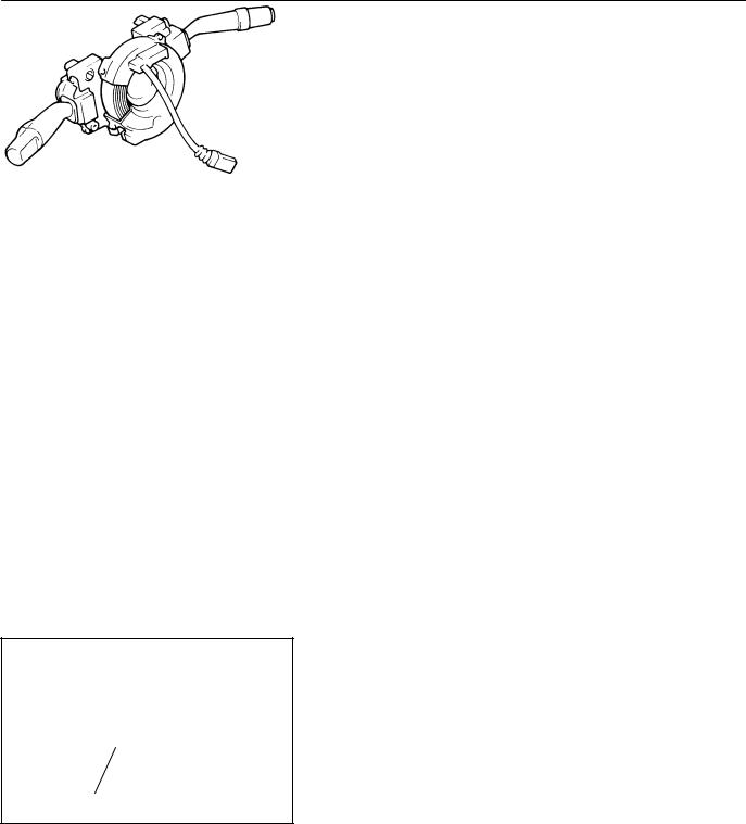
(c)SPIRAL CABLE (in Combination Switch)
The steering wheel must be fitted correctly to the steering column with the spiral cable at the neutral position, otherwise cable disconnection and other troubles may result. Refer to RS-19 of this manual concerning correct steering wheel installation.
Match Marks
R09725
1996 TERCEL (RM440U)
Author : |
Date : |
10 |
IN-1 1
INTRODUCTION - FOR ALL OF VEHICLES
(d)STEERING WHEEL PAD (with Airbag)
(1)When removing the steering wheel pad or handling a new steering wheel pad, it should be placed with the pad top surface facing up.
Storing the pad with its metallic surface facing upward may lead to a serious accident if the airbag deploys for some reason. In addition do not store a steering wheel pad on top of another one.
(2)Never measure the resistance of the airbag squib. (This may cause the airbag to deploy, which is very dangerous.)
(3)Grease should not be attached to the steering wheel pad and the pad should not be cleaned with detergents of any kind.
(4)Store the steering wheel pad where the ambient temperature remains below 93°C (200°F), without high humidity and away from electrical noise.
(5)When using electric welding, first disconnect the airbag connector (yellow color and 2 pins) under the steering column near the combination switch connector before starting work.
(6)When disposing of a vehicle or the steering wheel pad alone, the airbag should be deployed using an SST before disposal (See page RS-1 1).
Perform the operation in a safe place away from electrical noise.
Example: |
CORRECT WRONG |
Z13953 |
Example: |
Z13950 |
1996 TERCEL (RM440U)
Author : |
Date : |
11 |
IN-12
INTRODUCTION - FOR ALL OF VEHICLES
(e)FRONT PASSENGER AIRBAG ASSEMBLY
(1)Always store a removed or new front passenger airbag assembly with the airbag deployment direction facing up.
Storing the airbag assembly with the airbag deployment direction facing down could cause a serious accident if the airbag deploys.
(2)Never measure the resistance of the airbag squib. (This may cause the airbag to deploy, which is very dangerous.)
(3)Grease should not be attached to the front passenger airbag assembly and the airbag door should not be cleaned with detergents of any kind.
(4)Store the airbag assembly where the ambient temperature remains below 93°C (200°F), without high humidity and away from electrical noise.
(5)When using electric welding, first disconnect the airbag connector (yellow color and 2 pins) installed on the assembly before starting work.
(6)When disposing of a vehicle or the airbag assembly alone, the airbag should be deployed using an SST before disposal (See page RS-24 ).
Perform the operation in a safe place away from electrical noise.
Example: |
CORRECT |
WRONG |
Z13952 |
Example: |
Z13951 |
1996 TERCEL (RM440U)
Author : |
Date : |
12 |

IN-13
INTRODUCTION - FOR ALL OF VEHICLES
(f)AIRBAG SENSOR ASSEMBLY
(1)Never reuse the airbag sensor assembly involved in a collision when the SRS has deployed.
(2)The connectors to the airbag sensor assembly should be connected or disconnected with the sensor mounted on the floor. If the connectors are connected or disconnected while the airbag sensor assembly is not mounted to the floor, it could cause undesired deployment of the supplemental restraint system.
(3)Work must be started after 90 seconds from the time the ignition switch is turned to the ºLOCKº position and the negative (-) terminal cable is disconnected from the battery, even if only loosing the set bolts of the airbag sensor assembly.
(g)WIRE HARNESS AND CONNECTOR
The SRS wire harness is integrated with the instrument panel wire harness assembly and floor wire harness assembly. The wires for the SRS wire harness are encased in a yellow corrugated tube. All the connectors for the system are also a standard yellow color. If the SRS wire harness becomes disconnected or the connector becomes broken due to an accident, etc., repair or replace it as shown on page RS-37 .
1996 TERCEL (RM440U)
Author : |
Date : |
13 |

IN-14
INTRODUCTION - FOR ALL OF VEHICLES
2. FOR VEHICLES EQUIPPED WITH A CATALYTIC CONVERTER CAUTION:
If large amount of unburned gasoline flows into the converter, it may overheat and create a fire hazard. To prevent this, observe the following precautions and explain them to your customer.
(a)Use only unleaded gasoline.
(b)Avoid prolonged idling.
Avoid running the engine at idle speed for more than 20 minutes.
(c)Avoid spark jump test.
(1)Perform spark jump test only when absolutely necessary. Perform this test as rapidly as possible.
(2)While testing, never race the engine.
(d)Avoid prolonged engine compression measurement.
Engine compression tests must be done as rapidly as possible.
(e)Do not run engine when fuel tank is nearly empty.
This may cause the engine to misfire and create an extra load on the converter.
(f)Avoid coasting with ignition turned off.
(g)Do not dispose of used catalyst along with parts contaminated with gasoline or oil.
3.IF VEHICLE IS EQUIPPED WITH MOBILE COMMUNICATION SYSTEM
For vehicles with mobile communication systems such as two-way radios and cellular telephones, observe the following precautions.
(1)Install the antenna as far as possible away from the ECU and sensors of the vehicle's electronic system.
(2)Install the antenna feeder at least 20 cm (7.87 in.) away from the ECU and sensors of the vehicle's electronic systems. For details about ECU and sensors locations, refer to the section on the applicable component.
(3)Avoid winding the antenna feeder together with other wiring as much as possible, and also avoid running the antenna feeder parallel with other wire harnesses.
(4)Check that the antenna and feeder are correctly adjusted.
(5)Do not install powerful mobile communications system.
4.FOR USING OBD II SCAN TOOL OR TOYOTA HAND-HELD TESTER
CAUTION:
Observe the following items for safety reasons:
Before using the OBD II scan tool or TOYOTA hand-held tester, the OBD II scan tool's instruction book or TOYOTA hand-held tester's operator manual should be read thoroughly.
Be sure to route all cables securely when driving with the OBD II scan tool or TOYOTA handheld tester connected to the vehicle. (i.e. Keep cables away from feet, pedals, steering wheel and shift lever.)
Two persons are required when test driving with the OBD II scan tool or TOYOTA hand-held tester, one person to drive the vehicle and the other person to operate the OBD II scan tool or TOYOTA hand-held tester.
1996 TERCEL (RM440U)
Author : |
Date : |
14 |
INTRODUCTION - HOW TO TROUBLESHOOT ECU CONTROLLED |
IN-15 |
SYSTEMS |
|
HOW TO TROUBLESHOOT ECU CONTROLLED SYSTEMS
IN07E-05
GENERAL INFORMATION
A large number of ECU controlled systems are used in the TERCEL. In general, the ECU controlled system is considered to be a very intricate system requiring a high level of technical knowledge and expert skill to troubleshoot. However, the fact is that if you proceed to inspect the circuits one by one, troubleshooting of these systems is not complex. If you have adequate understanding of the system and a basic knowledge of electricity, accurate diagnosis and necessary repair can be performed to locate and fix the problem. This manual is designed through emphasis of the above standpoint to help service technicians perform accurate and effective troubleshooting, and is compiled for the following major ECU controlled systems:
The troubleshooting procedure and how to make use of it are described on the following pages.
|
System |
Page |
|
|
|
1. |
Engine |
DI-1 |
|
|
|
2. |
Anti-Lock Brake System |
DI-109 |
|
|
|
3. |
Supplemental Restraint System |
DI-146 |
|
|
|
4. |
Power Door Lock Control System |
DI-190 |
|
|
|
5. |
Theft Deterrent System |
DI-215 |
|
|
|
Before using the scan tool or tester, the scan tool's instruction book or tester's operator manual should be read thoroughly.
If the scan tool or tester cannot communicate with ECU controlled systems when you have connected the cable of the scan tool or tester to DLC3, turned the ignition switch ON and operated the scan tool, there is a problem on the vehicle side or tool side.
(1)If communication is normal when the tool is connected to another vehicle, inspect the diagnosis data link line (Bus line) or ECU power circuit of the vehicle.
(2)If communication is still not possible when the tool is connected to another vehicle, the problem is probably in the tool itself, so perform the Self Test procedures outline in the Tester Operator's Manual.
1996 TERCEL (RM440U)
Author : |
Date : |
15 |
IN-16 |
INTRODUCTION - HOW TO TROUBLESHOOT ECU CONTROLLED |
|
SYSTEMS |
IN07F-06
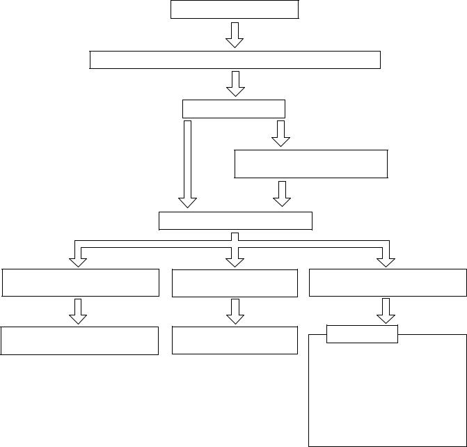
HOW TO PROCEED WITH TROUBLESHOOTING
Carry out troubleshooting in accordance with the procedure on the following page. Here, only the basic procedure is shown. Details are provided in Diagnostics section, showing the most effective methods for each circuit. Confirm the troubleshooting procedures first for the relevant circuit before beginning troubleshooting of that circuit.
Vehicle Brought to Workshop
1
1Customer Problem Analysis
2Symptom Confirmation and Diagnostic Trouble Code Check
Ask the customer about the conditions and the environment when the problem occurred.
3
Symptom Simulation
2, 3
4
6
7
8
Confirm the symptoms and the problem conditions, and check the diagnostic trouble codes.
(When the problem symptoms do not appear during confirmation, use the symptom simulation method described later on.)
Diagnostic Trouble
Code Chart
5
Problem Symptoms Table
Circuit Inspection or Parts Inspection
Repair
Confirmation Test
End
4, 5, 6
Check the results obtained in Step 2, then confirm the inspection procedure for the system or the part which should be checked using the diagnostic trouble code chart or the problem symptoms table.
7
Check and repair the affected system or part in accordance with the instructions in Step 6.
8
After completing repairs, confirm that the problem has been eliminated.
(If the problem is not reproduced, perform the confirmation test under the same conditions and in the same environment as when it occurred for the first time.)
1996 TERCEL (RM440U)
INTRODUCTION - HOW TO TROUBLESHOOT ECU CONTROLLED |
IN-17 |
SYSTEMS |
|
1.CUSTOMER PROBLEM ANALYSIS
In troubleshooting, the problem symptoms must be confirmed accurately and all preconceptions must be cleared away in order to give an accurate judgment. To ascertain just what the problem symptoms are, it is extremely important to ask the customer about the problem and the conditions at the time it occurred.
Important Point in the Problem Analysis:
The following 5 items are important points in the problem analysis. Past problems which are thought to be unrelated and the repair history, etc. may also help in some cases, so as much information as possible should be gathered and its relationship with the problem symptoms should be correctly ascertained for reference in troubleshooting. A customer problem analysis table is provided in Diagnostics section for each system for your use.
Important Points in the Customer Problem Analysis
What ----- Vehicle model, system name
When ----- Date, time, occurrence frequency
Where ----- Road conditions
Under what conditions? ----- Running conditions, driving conditions, weather conditions
How did it happen? ----- Problem symptoms
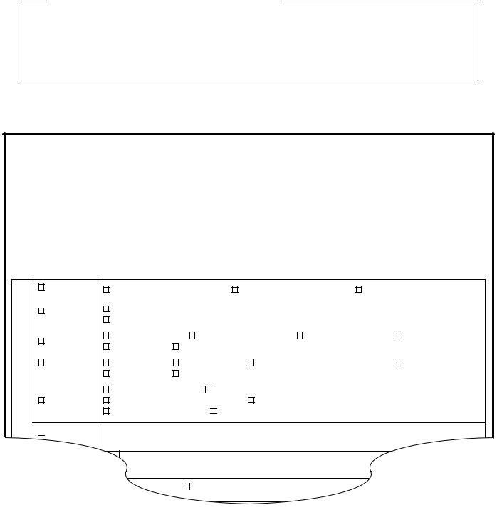
(Sample) Engine control system check sheet.
CUSTOMER PROBLEM ANALYSIS CHECK
ENGINE CONTROL SYSTEM Check Sheet |
|
Inspector's |
|
||
|
|
|
Name |
|
|
|
|
|
|
|
|
Customer's Name |
|
|
|
Model and Model |
|
|
|
|
Year |
|
|
|
|
|
|
|
|
Driver's Name |
|
|
|
Frame No. |
|
|
|
|
|
|
|
Data Vehicle |
|
|
|
Engine Model |
|
Brought in |
|
|
|
|
|
|
|
|
|
|
|
License No. |
|
|
|
Odometer Reading |
km |
|
|
|
miles |
||
|
|
|
|
|
|
Problem Symptoms
Engine does |
Engine does not crank |
|
No initial combustion |
No complete combustion |
|
|
|||||||
not Start |
|
|
|
||||||||||
|
|
|
|
|
|
|
|
|
|
|
|
|
|
Difficult to |
Engine cranks slowly |
|
|
|
|
|
|
|
|
||||
Start |
Other |
|
|
|
|
|
|
|
|
|
|
|
|
|
|
|
|
|
|
|
|
|
|
|
|
|
|
Poor Idling |
Incorrect first idle |
Idling rpm is abnormal |
High ( |
rpm) |
Low ( |
rpm) |
|||||||
Rough idling |
Other |
|
|
|
|
|
|
|
|
||||
|
|
|
|
|
|
|
|
|
|||||
|
|
|
|
|
|
|
|
|
|
|
|
|
|
Poor |
Hesitation |
Back fire |
|
|
Muffler explosion (after-fire) |
|
Surging |
|
|
||||
Drive ability |
Knocking |
Other |
|
|
|
|
|
|
|
|
|||
|
|
|
|
|
|
|
|
|
|||||
|
|
|
|
|
|
|
|
|
|
|
|
|
|
|
Soon after starting |
|
|
|
After accelerator pedal depressed |
|
|
|
|
||||
Engine Stall |
After accelerator pedal released |
|
During A/C operation |
|
|
|
|
||||||
|
Shifting from N to D |
Other |
|
|
|
|
|
|
|
||||

 Others
Data Problem
Constant |
Sometimes ( |
times per |
day/month) |
1996 TERCEL (RM440U)
IN-18 |
INTRODUCTION - HOW TO TROUBLESHOOT ECU CONTROLLED |
|
SYSTEMS |
2.SYMPTOM CONFIRMATION AND DIAGNOSTIC TROUBLE CODE CHECK
The diagnostic system in the TERCEL fulfills various functions. The first function is the Diagnostic Trouble Code Check in which a malfunction in the signal circuits to the ECU is stored in code in the ECU memory at the time of occurrence, to be output by the technician during troubleshooting. Another function is the Input Signal Check which checks if the signals from various switches are sent to the ECU correctly.
By using these check functions, the problem areas can be narrowed down quickly and troubleshooting can be performed effectively. Diagnostic functions are incorporated in the following systems in the TERCEL.
|
System |
Diagnostic Trouble |
Input Signal Check |
Diagnostic Test |
|
Code Check |
(Sensor Check) |
Mode (Active Test) |
|
|
|
|||
|
|
|
|
|
1. |
Engine |
|
|
|
|
|
(with Check Mode) |
|
|
|
|
|
|
|
2. |
Anti-Lock Brake System |
|
|
|
|
|
|
|
|
3. |
Supplemental Restraint System |
|
|
|
|
|
|
|
|
4. |
Power Door Lock Control System |
|
|
|
|
|
|
|
|
5. |
Theft Deterrent System |
|
|
|
|
|
|
|
|
In diagnostic trouble code check, it is very important to determine whether the problem indicated by the diagnostic trouble code is still occurring or occurred in the past but returned to normal at present. In addition, it must be checked in the problem symptom check whether the malfunction indicated by the diagnostic trouble code is directly related to the problem symptom or not. For this reason, the diagnostic trouble codes should be checked before and after the symptom confirmation to determine the current conditions, as shown in the table below. If this is not done, it may, depending on the case, result in unnecessary troubleshooting for normally operating systems, thus making it more difficult to locate the problem, or in repairs not pertinent to the problem. Therefore, always follow the procedure in correct order and perform the diagnostic trouble code check.
DIAGNOSTIC TROUBLE CODE CHECK PROCEDURE
Diagnostic Trouble |
Confirmation |
Diagnostic Trouble |
Problem Condition |
|
Code Check (Make a |
||||
of Symptoms |
Code Check |
|||
note of and then clear) |
|
|||
|
|
|
||
|
|
|
|
|
Diagnostic Trouble |
Problem symptoms |
Same diagnostic |
Problem is still occurring in the diagnostic |
|
Code Display |
exist |
trouble code is |
circuit |
|
|
|
displayed |
|
|
|
|
|
|
|
|
|
Normal code is |
The problem is still occurring in a place |
|
|
|
displayed |
other than in the diagnostic circuit |
|
|
|
|
(The diagnostic trouble code displayed |
|
|
|
|
first is either for a past problem or it is a |
|
|
|
|
secondary problem) |
|
|
|
|
|
|
|
No problem |
|
The problem occurred in the diagnostic |
|
|
symptoms exist |
|
circuit in the past |
|
|
|
|
|
|
Normal Code Display |
Problem symptoms |
Normal code is |
The problem is still occurring in a place |
|
|
exist |
displayed |
other than in the diagnostic circuit |
|
|
|
|
|
|
|
No problem |
Normal code is |
The problem occurred in a place other |
|
|
symptoms exist |
displayed |
than in the diagnostic circuit in the past |
|
|
|
|
|
1996 TERCEL (RM440U)
INTRODUCTION - HOW TO TROUBLESHOOT ECU CONTROLLED |
IN-19 |
SYSTEMS |
|
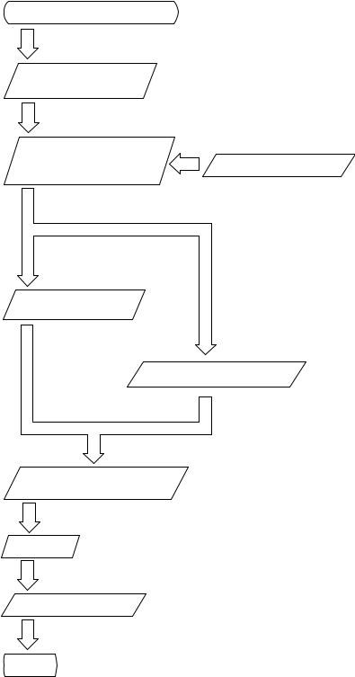
Taking into account the points on the previous page, a flow chart showing how to proceed with troubleshooting using the diagnostic trouble code check is shown below. This flow chart shows how to utilize the diagnostic trouble code check effectively, then by carefully checking the results, indicates how to proceed either to diagnostic trouble code troubleshooting or to troubleshooting of problem symptoms table.
Diagnostic trouble code check
Making a note of and clearing of the diagnostic trouble codes displayed
Symptom confirmation
Problem symptoms |
No problem symptoms |
||
exist |
|||
exist |
|
||
|
|
||
|
Simulation test using the symptom |
||
|
simulation methods |
||
Diagnostic trouble code check
Diagnostic trouble code displayed
Problem symptoms exist
Troubleshooting of problem indicated by diagnostic trouble code
Normal code displayed
Problem symptoms exist
Troubleshooting of each problem symptom
Normal code displayed
No problem symptoms exist
System Normal
If a diagnostic trouble code was displayed in the initial diagnostic trouble code check, it indicates that the trouble may have occurred in a wire harness or connector in that circuit in the past. Therefore, check the wire harness and connectors (See page IN-26 ).
1996 TERCEL (RM440U)
IN-20 |
INTRODUCTION - HOW TO TROUBLESHOOT ECU CONTROLLED |
|
SYSTEMS |
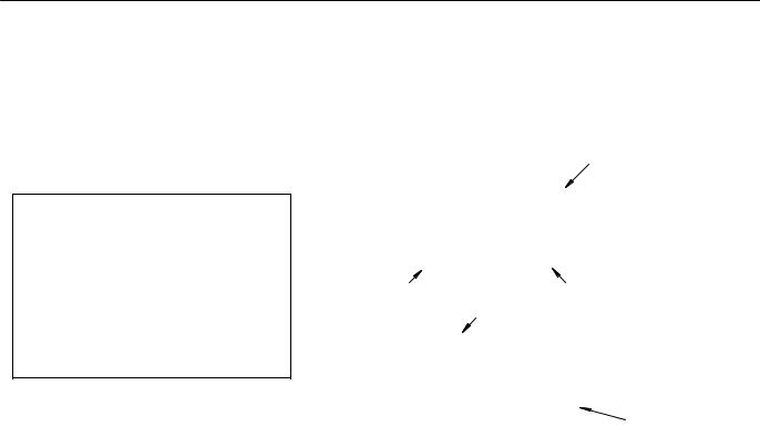
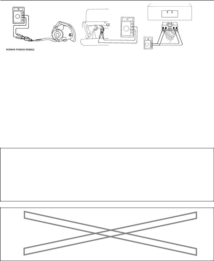
3.SYMPTOM SIMULATION
The most difficult case in troubleshooting is when there are no problem symptoms occurring. In such cases, a thorough customer problem analysis must be carried out, then simulate the same or similar conditions and environment in which the problem occurred in the customer's vehicle. No matter how much experience a technician has, or how skilled he may be, if he proceeds to troubleshoot without confirming the problem symptoms he will tend to overlook something important in the repair operation and make a wrong guess somewhere, which will only lead to a standstill. For example, for a problem which only occurs when the engine is cold, or for a problem which occurs due to vibration caused by the road during driving, etc., the problem can never be determined so long as the symptoms are confirmed with the engine hot condition or the vehicle at a standstill. Since vibration, heat or water penetration (moisture) is likely cause for problem which is difficult to reproduce, the symptom simulation tests introduced here are effective measures in that the external causes are applied to the vehicle in a stopped condition.
Important Points in the Symptom Simulation Test:
In the symptom simulation test, the problem symptoms should of course be confirmed, but the problem area or parts must also be found out. To do this, narrow down the possible problem circuits according to the symptoms before starting this test and connect a tester beforehand. After that, carry out the symptom simulation test, judging whether the circuit being tested is defective or normal and also confirming the problem symptoms at the same time. Refer to the problem symptoms table for each system to narrow down the possible causes of the symptom.
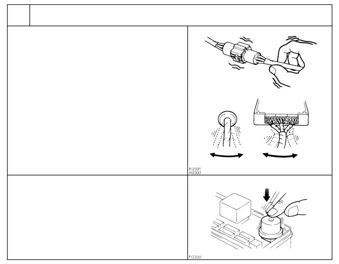
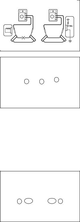
1 VIBRATION METHOD: When vibration seems to be the major cause.
CONNECTORS
Slightly shake the connector vertically and horizontally.
Shake Slightly
WIRE HARNESS
Slightly shake the wire harness vertically and horizontally. The connector joint, fulcrum of the vibration, and body through portion are the major areas to be checked thoroughly.
PARTS AND SENSOR
Apply slight vibration with a finger to the part of the sensor considered to be the problem cause and check that the malfunction occurs.
HINT:
Applying strong vibration to relays may result in open relays.
Swing Slightly
Vibrate Slightly
V07268
1996 TERCEL (RM440U)
INTRODUCTION - HOW TO TROUBLESHOOT ECU CONTROLLED |
IN-21 |
SYSTEMS |
|
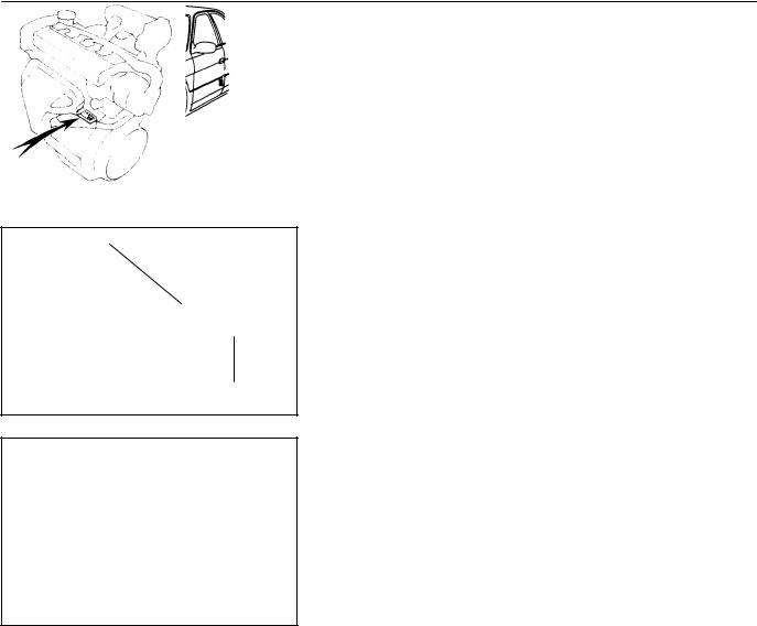
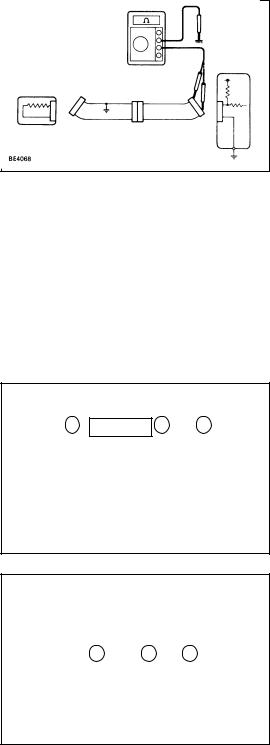
2 HEAT METHOD: When the problem seems to occur when the suspect area is heated.
Heat the component that is the likely cause of the malfunction with a hair dryer or similar object. Check to see if the malfunction occurs.
NOTICE:
(1)Do not heat to more than 60°C (140°F). (Temperature is limited not to damage the components.)
(2)Do not apply heat directly to parts in the ECU.
M a l f u n c- tion
3 WATER SPRINKLING METHOD: When the malfunction seems to occur on a rainy day or in a high-humidity condition.
Sprinkle water onto the vehicle and check to see if the malfunction occurs.
NOTICE:
(1)Never sprinkle water directly into the engine compartment, but indirectly change the temperature and humidity by applying water spray onto the radiator front surface.
(2)Never apply water directly onto the electronic components.
HINT:
If a vehicle is subject to water leakage, the leaked water may contaminate the ECU. When testing a vehicle with a water leakage problem, special caution must be taken.
4 OTHER: When a malfunction seems to occur when electrical load is excessive.
Turn on all electrical loads including the heater blower, head |
ON |
lights, rear window defogger, etc. and check to see if the mal- |
|
function occurs. |
|
B02389
B02390
1996 TERCEL (RM440U)
IN-22 |
INTRODUCTION - HOW TO TROUBLESHOOT ECU CONTROLLED |
|
SYSTEMS |
4.DIAGNOSTIC TROUBLE CODE CHART
The inspection procedure is shown in the table below. This table permits efficient and accurate troubleshooting using the diagnostic trouble codes displayed in the diagnostic trouble code check. Proceed with troubleshooting in accordance with the inspection procedure given in the diagnostic chart corresponding to the diagnostic trouble codes displayed. The engine diagnostic trouble code chart is shown below as an example.
DTC No.
Indicates the diagnostic trouble code.
Page or Instructions
Indicates the page where the inspection procedure for each circuit is to be found, or gives instructions for checking and repairs.
Trouble Area
Indicates the suspect area of the problem.
Detection Item
Indicates the system of the problem or contents of the problem.
DIAGNOSTIC TROUBLE CODE CHART
HINT:
Parameters listed in the chart may not be exactly the same as your reading due to the type of instrument or other factors.
If a malfunction code is displayed during the DTC check mode, check the circuit for the code listed in the table below. For details of each code, turn to the page referred to under the ºSee pageº for the respective ºDTC No.º in the DTC chart.
SAE CONTROLLED
DTC No. |
Detection Item |
Trouble Area |
MIL* |
Memory |
||
(See page) |
||||||
|
|
|
|
|||
|
|
|
|
|
|
|
P0100 |
|
Open or short in mass air flow meter circuit |
|
|
||
Mass Air Flow Circuit Malfunction |
Mass air flow meter |
|
|
|||
(DI-24) |
|
|
||||
|
ECM |
|
|
|||
|
|
|
|
|
||
|
|
|
|
|
|
|
P0101 |
Mass Air Flow Circuit |
Mass air flow meter |
|
|
||
(DI-28) |
Range/ Performance Problem |
|
|
|||
|
|
|
||||
|
|
|
|
|
|
|
|
|
|
Open or short in intake air temp. sensor |
|
|
|
P0110 |
Intake Air Temp. Circuit |
circuit |
|
|
||
(DI-29) |
Malfunction |
Intake air temp. sensor |
|
|
||
|
|
|
ECM |
|
|
|
|
|
|
|
|
|
|
P0115 |
Engine Coolant Temp. |
Open or short in engine coolant temp. sensor circuit |
|
|
||
Engine coolant temp. sensor |
|
|
||||
(DI-33) |
Circuit Malfunction |
|
|
|||
ECM |
|
|
||||
|
|
|
|
|
||
P0116 |
Engine Coolant Temp. |
Engine coolant temp. sensor |
|
|
||
(DI-37) |
Circuit Range/ Performance Problem |
Cooling system |
|
|
||
|
|
|
|
|
|
|
|
|
Throttle/ Pedal Position Sensor/Switch |
Open or short in throttle position sensor circuit |
|
|
|
|
|
Throttle position sensor |
|
|
||
|
|
ºAº Circuit Malfunction |
|
|
||
|
|
ECM |
|
|
||
|
|
|
|
|
||
|
|
|
|
|
|
|
|
|
Throttle/ Pedal Position Sensor/ Switch |
|
|
|
|
|
|
ºAº Circuit Range / Performance Prob- |
Throttle position sensor |
|
|
|
|
|
lem |
|
|
|
|
|
|
|
|
|
||
1996 TERCEL (RM440U)
INTRODUCTION - HOW TO TROUBLESHOOT ECU CONTROLLED |
IN-23 |
SYSTEMS |
|
5.PROBLEM SYMPTOMS TABLE
The suspected circuits or parts for each problem symptom are shown in the table below. Use this table to troubleshoot the problem when a ºNormalº code is displayed in the diagnostic trouble code check but the problem is still occurring. Numbers in the table indicate the inspection order in which the circuits or parts should be checked.
HINT:
When the problem is not detected by the diagnostic system even though the problem symptom is present, it is considered that the problem is occurring outside the detection range of the diagnostic system, or that the problem is occurring in a system other than the diagnostic system.
Page
Indicates the page where the flow chart for each circuit is located.
Circuit Inspection, Inspection Order
Indicates the circuit which needs to be checked for each problem symptom. Check in the order indicated by the numbers.
Problem Symptom |
Circuit or Part Name |
Indicates the circuit or part which needs to be checked. |
PROBLEM SYMPTOMS TABLE
|
|
|
|
|
|
|
|
|
|
Symptom |
|
Suspected Area |
See page |
||||||
|
|
|
|
|
|
|
|
|
|
Engine does not crank (Does not start) |
1. Starter and starter relay |
ST-2 |
|||||||
ST-17 |
|||||||||
|
|
|
|
|
|
|
|
||
|
|
|
1. ECM power source circuit |
DI-147 |
|||||
No initial combustion (Does not start) |
2. Fuel pump control circuit |
DI-151 |
|||||||
|
|
|
3. ECM |
IN-29 |
|||||
No complete combustion (Does not start) |
1. Fuel pump control circuit |
DI-151 |
|||||||
|
|
|
|
|
|
|
|
||
|
|
|
1. Starter signal circuit |
DI-144 |
|||||
Engine cranks normally (Difficult to start) |
2. Fuel pump control circuit |
DI-151 |
|||||||
|
|
|
3. Compression |
EM-3 |
|||||
|
|
|
|
|
|
|
|
|
|
Cold engine (Difficult to start) |
1. |
Starter signal circuit |
DI-144 |
||||||
DI-151 |
|||||||||
2. |
Fuel pump control circuit |
||||||||
|
|
|
|||||||
|
|
|
|
||||||
|
|
|
|
|
|
|
|
|
|
Hot engine |
1. |
Starter signal circuit |
DI-144 |
||||||
2. |
Fuel pump control circuit |
DI-151 |
|||||||
|
|
|
|||||||
|
|
|
|
|
|
|
|
|
|
High engine idle speed (Poor idling) |
1. |
A/C signal circuit (Compressor circuit) |
AC-88 |
||||||
2. |
ECM power source circuit |
|
|||||||
|
|
|
|
||||||
|
|
|
|
|
|
|
|
|
|
|
idling) |
1. |
A/C signal circuit |
|
|||||
|
2. |
Fuel pump control circuit |
|
||||||
|
|
||||||||
|
|
|
|
||||||
|
|
|
|
|
|
|
|||
|
|
|
1. Compression |
|
|||||
|
|
|
2. |
Fuel pump control circuit |
|
||||
|
|
|
|
||||||
1996 TERCEL (RM440U)
IN-24 |
INTRODUCTION - HOW TO TROUBLESHOOT ECU CONTROLLED |
|
SYSTEMS |
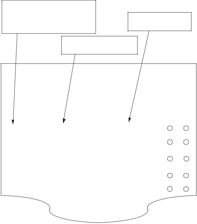
6.CIRCUIT INSPECTION
How to read and use each page is shown below.
Diagnostic Trouble Code No. and Detection Item
Circuit Description
The major role and operation, etc. of the circuit and its component parts are explained.
|
|
|
|
DTC |
P0325 |
Knock Sensor 1 Circuit Malfunction |
|
|
|
|
|
CIRCUIT DESCRIPTION
Knock sensor is fitted to the cylinder block to detect engine knocking. This sensor contains a piezoelectric element which generates a voltage when it becomes deformed, which occurs when the cylinder block vibrates due to knocking. If engine knocking occurs, ignition timing is retarded to suppress it.
DTC No. |
DTC Detection Condition |
|
Trouble Area |
|
|
|
|
|
No knock sensor 1 signal to ECM with engine speed, |
|
Open or short in knock sensor1 circuit |
P0325 |
|
Knock sensor 1 (looseness) |
|
1,200 rpm or more. |
|
||
|
|
|
|
|
|
|
ECM |
If the ECM detects the above diagnosis conditions, it operates the fall safe function in which the corrective retard angle value is set to the maximum value.
WIRING DIAGRAM
ECM
Knock Sensor 1
GR |
12 KNK |
|
E6 |
E1
Indicates the diagnostic trouble code, diagnostic trouble code set parameter and suspect area of the problem.
Wiring Diagram
This shows a wiring diagram of the circuit. Use this diagram together with ELECTRICAL
WIRING DIAGRAM to thoroughly understand the circuit.
Wire colors are indicated by an alphabetical code. B = Black, L = Blue, R = Red, BR = Brown,
LG = Light Green, V = Violet, G = Green,
O = Orange, W = White, GR = Gray, P = Pink, Y = Yellow, SB = Sky Blue
The first letter indicates the basic wire color and the second letter indicates the color of the stripe.
V08423
1996 TERCEL (RM440U)
INTRODUCTION - HOW TO TROUBLESHOOT ECU CONTROLLED |
IN-25 |
SYSTEMS |
|
Indicates the position of the ignition switch during the check.
LOCK |
ON |
|
Ignition Switch LOCK (OFF) |
Ignition Switch ON |
|
|
START |
ACC |
Ignition Switch START |
Ignition Switch ACC |
|
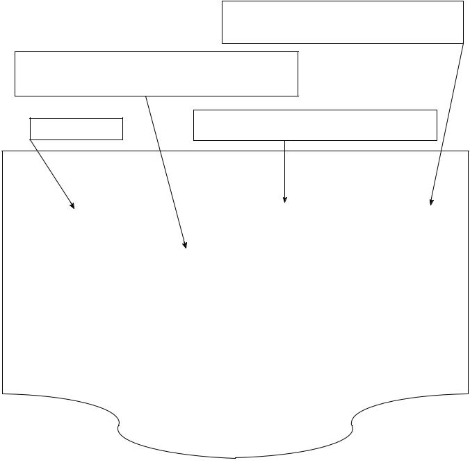
Inspection Procedure
Use the inspection procedure to determine if the circuit is normal or abnormal, and, if it is abnormal, use it to determine whether the problem is located in the sensors, actuators, wire harness or ECU.
INSPECTION PROCEDURE
1 Check continuity between terminal KNK of ECM connector and body ground.
LOCK |
|
PREPARATION: |
|
KNK |
|
(a) Remove the glove compartment (See page SF-68). |
|
|
|
(b) Disconnect the E6 connector from the ECM. |
|
|
|
CHECK: |
|
|
|
Measure the resistance between terminal KNK of the ECM connec- |
|
|
|
tor and body ground. |
|
|
E6 Connector |
OK: |
|
AB0117 |
|
|
Resistance: 1 MΩ or higher |
A00265 |
A00255 |
|
|
|
|
OK |
Go to step 3. |
|
|
||
NG |
|
|
|
2 Check knock sensor (See page SF-61).
OK |
Replace knock sensor. |
Indicates the place to check the voltage or resistance.
Indicates the connector position to checked, from the front or back side.
Wire Harness
Check from the connector back side. (with harness)
Check from the connector front side. (without harness) In this case, care must be taken not to bend the terminals.
Indicates the condition of the connector of ECU during the check. |
KNK |
KNK |
E6 Connector |
E6 Connector |
Connector being checked is connected.
Connector being checked is disconnected.
V08425
1996 TERCEL (RM440U)
IN-26 |
INTRODUCTION - HOW TO TROUBLESHOOT ECU CONTROLLED |
|
SYSTEMS |
IN05X-13
FI0046
FI0047
FI0048
HOW TO USE THE DIAGNOSTIC CHART AND INSPECTION PROCEDURE
1.CONNECTOR CONNECTION AND TERMINAL IN-
SPECTION
For troubleshooting, diagnostic trouble code charts or problem symptom table are provided for each circuit with detailed inspection procedures on the following pages.
When all the component parts, wire harnesses and connectors of each circuit except the ECU are found to be normal in troubleshooting, then it is determined that the problem is in the ECU. Accordingly, if diagnosis is performed without the problem symptoms occurring, refer to Step 8 to replace the ECU. So always confirm that the problem symptoms are occurring, or proceed with inspection while using the symptom simulation method.
The instructions ºCheck wire harness and connectorº and
ºCheck and replace ECUº which appear in the inspection procedure, are common and applicable to all diagnostic trouble codes. Follow the procedure outlined below whenever these instructions appear.
OPEN CIRCUIT:
This could be due to a disconnected wire harness, faulty contact in the connector, a connector terminal pulled out, etc. HINT:
It is rarely the case that a wire is broken in the middle of it. Most cases occur at the connector. In particular, carefully check the connectors of sensors and actuators
Faulty contact could be due to rusting of the connector terminals, to foreign materials entering terminals or a deformation of connector terminals. Simply disconnecting and reconnecting the connectors once changes the condition of the connection and may result in a return to normal operation. Therefore, in troubleshooting, if no abnormality is found in the wire harness and connector
check, but the problem disappears after the check, then the cause is considered to be in the wire harness or connectors.
SHORT CIRCUIT:
This could be due to a contact between wire harness and the body ground or to a short circuit occurred inside the switch, etc. HINT:
When there is a short circuit between the wire harness and body ground, check thoroughly whether the wire harness is caught in the body or is clamped properly.
1996 TERCEL (RM440U)
INTRODUCTION - HOW TO TROUBLESHOOT ECU CONTROLLED |
IN-27 |
SYSTEMS |
|
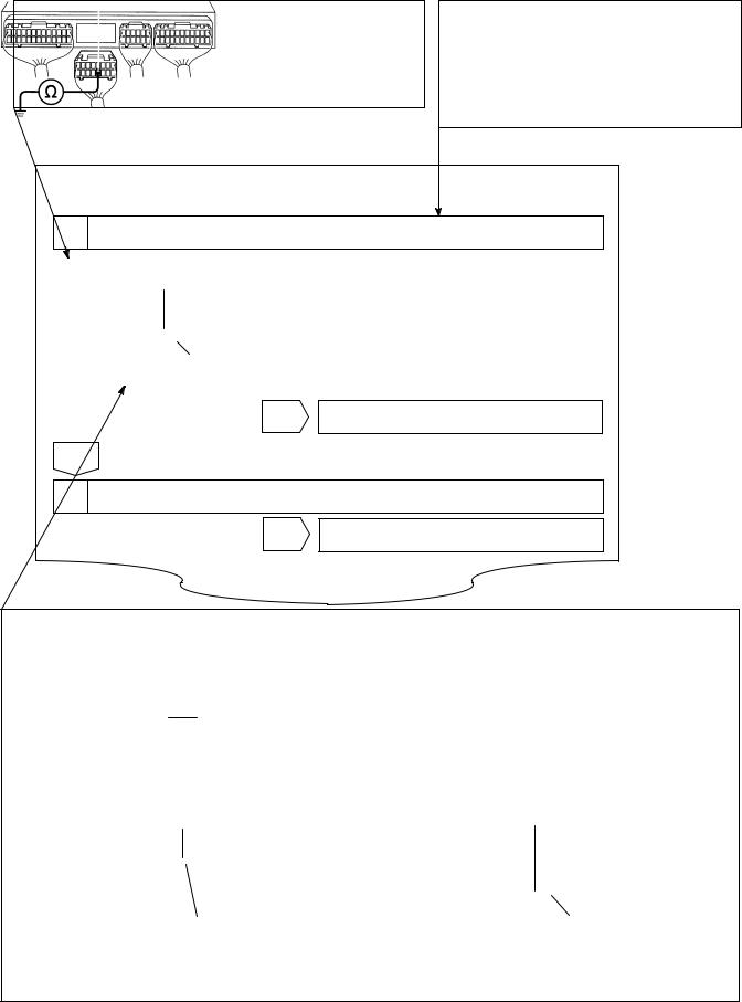
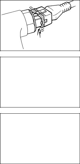
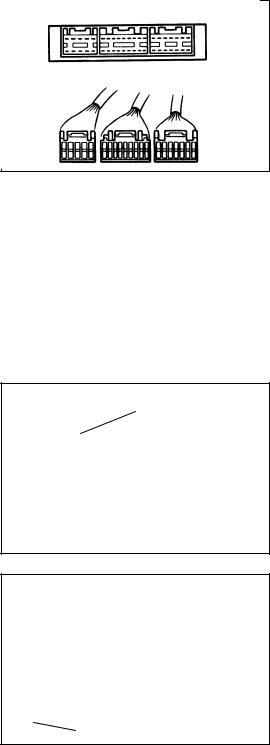
2.CONNECTOR HANDLING
When inserting tester probes into a connector, insert them from the rear of the connector. When necessary, use mini test leads. For water resistant connectors which cannot be accessed from behind, take good care not to deform the connector terminals.
FI7187
Sensor Side |
ECU Side |
3. |
CONTINUITY CHECK (OPEN CIRCUIT CHECK) |
|
(a) |
Disconnect the connectors at both ECU and sensor |
|||
|
||||
|
|
|
sides. |
IN0379
|
ECU Side |
(b) Measure the resistance between the applicable terminals |
|
of the connectors. |
|
|
|
|
Sensor Side |
|
Resistance: 1 Ω or less |
|
HINT: |
|
|
|
|
|
|
Measure the resistance while lightly shaking the wire harness |
|
|
vertically and horizontally. |
IN0378
ECU Side
Sensor Side
IN0380
Pull Lightly
Looseness of Crimping
IN0381
4.RESISTANCE CHECK (SHORT CIRCUIT CHECK)
(a)Disconnect the connectors on both ends.
(b)Measure the resistance between the applicable terminals of the connectors and body ground. Be sure to carry out this check on the connectors on both ends.
Resistance: 1 MΩ or higher
HINT:
Measure the resistance while lightly shaking the wire harness vertically and horizontally.
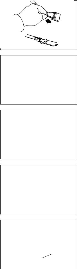
5.VISUAL CHECK AND CONTACT PRESSURE CHECK
(a)Disconnect the connectors at both ends.
(b)Check for rust or foreign material, etc. in the terminals of the connectors.
(c)Check crimped portions for looseness or damage and
check that the terminals are secured in lock portion.
HINT:
The terminals should not come out when pulled lightly from the back.
1996 TERCEL (RM440U)
IN-28 |
INTRODUCTION - HOW TO TROUBLESHOOT ECU CONTROLLED |
|
SYSTEMS |
Fig. 1
|
|
|
|
ECU |
|
Sensor |
C OPEN |
|
B |
A |
|
1 |
1 |
1 |
1 |
||
|
|||||
|
2 |
2 |
2 |
2 |
Z17004
(d)Prepare a test male terminal and insert it in the female ter-
minal, then pull it out.
NOTICE:
When testing a gold-plated female terminal, always use a gold-plated male terminal.
HINT:
When the test terminal is pulled out more easily than others, there may be poor contact in that section.
6.CHECK OPEN CIRCUIT
For the open circuit in the wire harness in Fig. 1, perform º(a) Continuity Checkº or º(b) Voltage Checkº to locate the section.
Fig. 2
ECU
Sensor |
C |
B |
A |
|
1 |
||||
|
1 |
1 |
||
|
2 |
2 |
2 |
Z17005
(a)Check the continuity.
(1)Disconnect connectors ºAº and ºCº and measure the resistance between them.
In the case of Fig. 2:
Between terminal 1 of connector ºAº and terminal 1 of connector ºCº → No continuity (open)
Between terminal 2 of connector ºAº and terminal 2 of connector ºCº → Continuity
Therefore, it is found out that there is an open circuit between terminal 1 of connector ºAº and terminal 1 of connector ºCº.
Fig. 3
ECU
Sensor
C |
B2 |
1 B1 |
A |
1 |
1 |
1 |
1 |
2 |
2 |
2 |
2 |
B04722
(2)Disconnect connector ºBº and measure the resistance between the connectors.
In the case of Fig. 3:
Between terminal 1 of connector ºAº and terminal 1 of connector ºB1º → Continuity
Between terminal 1 of connector ºB2º and terminal 1 of connector ºCº → No continuity (open)
Therefore, it is found out that there is an open circuit between terminal 1 of connector ºB2º and terminal 1 of connector ºCº.
1996 TERCEL (RM440U)
INTRODUCTION - HOW TO TROUBLESHOOT ECU CONTROLLED |
IN-29 |
SYSTEMS |
|
Fig. 4
|
|
|
|
|
5V |
|
Sensor |
0V |
|
|
|
|
|
|
|
|
|
A |
|
|
C |
|
B 1 |
5V |
|||
|
5V |
|||||
|
|
|||||
1 |
1 |
|
||||
|
|
|||||
2 |
|
|
2 |
2 |
|
|
Z17007
(b)Check the voltage.
In a circuit in which voltage is applied (to the ECU connector terminal), an open circuit can be checked for by conducting a voltage check.
As shown in Fig. 4, with each connector still connected, measure the voltage between body ground and terminal 1 of connector ºAº at the ECU 5V out-
put terminal, terminal 1 of connector ºBº, and terminal 1 of connector ºCº, in that order.
If the results are:
5V: Between Terminal 1 of connector ºAº and Body Ground 5V: Between Terminal 1 of connector ºBº and Body Ground 0V: Between Terminal 1 of connector ºCº and Body Ground Then it is found out that there is an open circuit in the wire harness between terminal 1 of ºBº and terminal 1 of ºCº.
Fig. 5
C |
SHORT B |
A |
1 |
1 |
1 |
2 |
2 |
2 |
Z17008
7.CHECK SHORT CIRCUIT
If the wire harness is ground shorted as in Fig. 5, locate the section by conducting a ºcontinuity check with groundº.
Fig. 6
ECU
Sensor |
C |
B |
A |
|
1 |
1 |
1 |
||
|
||||
|
2 |
2 |
2 |
Z17009
Check the continuity with ground.
(1)Disconnect connectors ºAº and ºCº and measure the resistance between terminal 1 and 2 of connector ºAº and body ground.
In the case of Fig. 6:
Between terminal 1 of connector ºAº and body ground → Continuity (short)
Between terminal 2 of connector ºAº and body ground → No continuity
Therefore, it is found out that there is a short circuit between terminal 1 of connector ºAº and terminal 1 of connector ºCº.
1996 TERCEL (RM440U)
IN-30 |
INTRODUCTION - HOW TO TROUBLESHOOT ECU CONTROLLED |
|
SYSTEMS |
Fig. 7
ECU
Sensor |
C |
B2 |
B1 |
A |
|
1 |
1 |
1 |
1 |
||
|
|||||
|
2 |
2 |
2 |
2 |
Z17808
(2)Disconnect connector ºBº and measure the resistance between terminal 1 of connector ºAº and body ground, and terminal 1 of connector ºB2º and body ground.
In the case of Fig. 7:
Between terminal 1 of connector ºAº and body ground → No continuity
Between terminal 1 of connector ºB2º and body ground → Continuity (short)
Therefore, it is found out that there is a short circuit between terminal 1 of connector ºB2º and terminal 1 of connector ºCº.
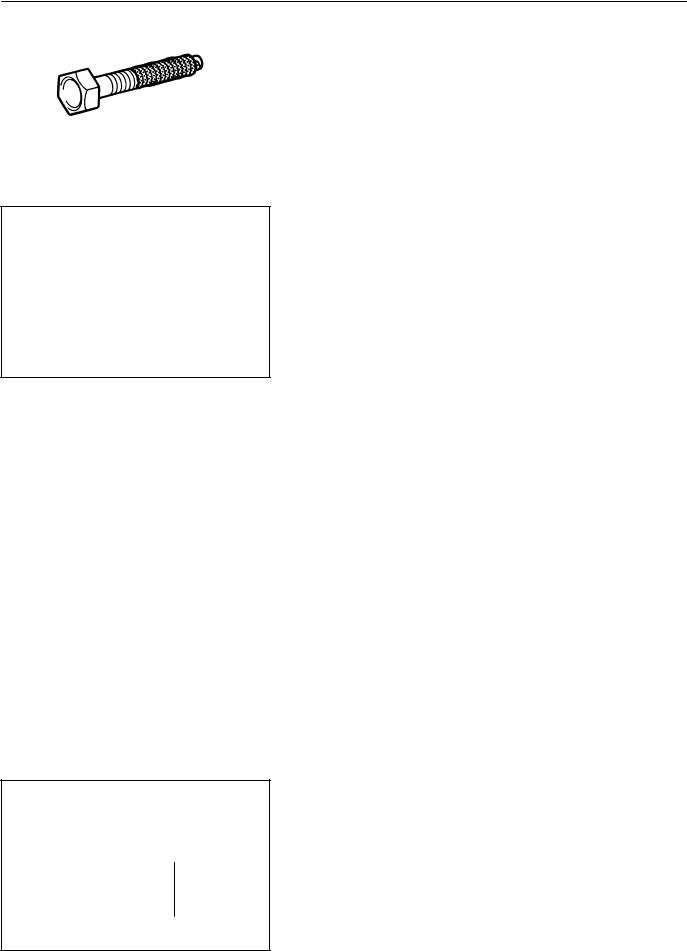
8.CHECK AND REPLACE ECU
First check the ECU ground circuit. If it is faulty, repair it. If it is normal, the ECU could be faulty, so replace the ECU with a normal functioning one and check that the symptoms appear.
(1) Measure the resistance between the ECU ground
Example
terminal and the body ground.
Resistance: 1 Ω or less
Ground
IN0383
ECU Side
 Ground
W/H Side
Ground
IN0384
(2)Disconnect the ECU connector, check the ground terminals on the ECU side and the wire harness side for bend and check the contact pressure.
1996 TERCEL (RM440U)
Loading...