


 Loading...
XR-CA600X/CA620X
SERVICE MANUAL |
US Model |
Ver 1.1 2001.05 |
Canadian Model |
XR-CA600X |
|
|
E Model |
|
XR-CA620X |
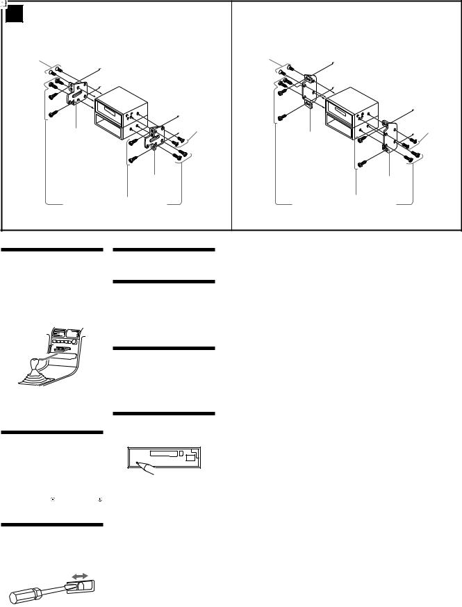
Photo: XR-CA600X
Model Name Using Similar Mechanism |
XR-C5300X/C5600X |
|
|
Tape Transport Mechanism Type |
MG-25F-136 |
SPECIFICATIONS
AUDIO POWER SPECIFICATIONS (US model only)
POWER OUTPUT AND TOTAL HARMONIC DISTORTION
23 watts per channel minimum continuous average power into 4 ohms, 4 channels driven from 20 Hz to 20 kHz with no more than 5% total harmonic distortion.
Cassette Player section
Tape track |
4-track 2-channel stereo |
|
Wow and flutter |
0.08 % (WRMS) |
|
Frequency response |
30 – 18,000 Hz |
|
Signal-to-noise ratio |
|
|
|
Cassette type |
|
|
|
|
|
TYPE II, IV |
61 dB |
|
|
|
|
TYPE I |
58 dB |
Tuner section |
|
|
|
|
|
FM |
|
|
Tuning range |
|
|
XR-CA600X: |
87.5 – 107.9 MHz |
|
XR-CA620X: |
FM tuning interval: |
|
|
50 kHz/200 kHz switchable |
|
|
87.5 – 108.0 MHz |
|
|
(at 50 kHz step) |
|
|
87.5 – 107.9 MHz |
|
|
(at 200 kHz step) |
|
Aerial terminal |
External aerial connector |
|
Intermediate frequency |
10.7 MHz/450 kHz |
|
Usable sensitivity |
8 dBf |
|
Selectivity |
75 dB at 400 kHz |
|
Signal-to-noise ratio |
66 dB (stereo), |
|
|
72 dB (mono) |
|
Harmonic distortion at 1 kHz |
|
|
|
0.6 % (stereo), |
|
|
0.3 % (mono) |
|
Separation |
35 dB at 1 kHz |
|
Frequency response |
30 – 15,000 Hz |
|
AM (XR-CA600X)
Tuning range |
530 – 1,710 kHz |
Antenna terminal |
External antenna connector |
Intermediate frequency |
10.7 MHz/450 kHz |
Sensitivity |
30 µ V |
MW (XR-CA620X) |
|
Tuning range |
MW tuning interval: |
|
9 kHz/10 kHz switchable |
|
531 – 1,602 kHz |
|
(at 9 kHz step) |
|
530 – 1,710 kHz |
SW (XR-CA620X) |
(at 10 kHz step) |
|
|
Tuning range |
SW tuning interval: |
|
SW1: 2,940 – 7,735 kHz |
|
SW2: 9,500 – 18,135 kHz |
|
(except for 10,140 – 11,575 |
|
kHz) |
Aerial terminal |
External aerial connector |
Intermediate frequency |
10.7 MHz/450 kHz |
Sensitivity |
30 µ V (at MW) |
|
40 µ V (at SW) |
Power amplifier section |
|
Outputs |
Speaker outputs |
|
(sure seal connectors) |
Speaker impedance |
4 – 8 ohms |
Maximum power output |
50 W × 4 (at 4 ohms) |
General
Outputs |
Audio outputs |
|
|
|
Power aerial relay control |
||
|
lead |
|
|
|
Power amplifier control lead |
||
Inputs |
BUS control input |
|
|
|
connector |
|
|
|
BUS audio input connector |
||
|
Remote controller input |
||
|
connector |
|
|
|
Aerial input connector |
||
Tone controls |
Bass ± 8 dB at 100 Hz |
||
|
Treble ± 8 dB at 10 kHz |
||
Loudness |
100 Hz +8 dB |
|
|
|
10 kHz +2 dB |
|
|
Power requirements |
12 V DC car battery |
|
|
|
(negative earth) |
|
|
Dimensions |
Approx. 178 × |
50 × |
176 |
|
mm (w/h/d) |
|
|
Mounting dimensions |
Approx. 182 × |
53 × |
161 |
|
mm (w/h/d) |
|
|
Mass |
Approx. 1.2 kg |
|
|
Supplied accessories |
Card remote commander |
||
|
(XR-CA620X only) (1) |
||
|
Parts for installation and |
||
|
connections (1 set) |
|
|
|
Front panel case (1) |
|
|
Note
This unit cannot be connected to a digital preamplifier or an equalizer.
Design and specifications are subject to change without notice.
FM/AM CASSETTE CAR STEREO
9-870-248-12 |
Sony Corporation |
2001E0500-1 |
e Vehicle Company |
C 2001.5 |
Shinagawa Tec Service Manual Production Group |
XR-CA600X/CA620X
TABLE OF CONTENTS |
|
1. GENERAL |
|
Location of Controls ....................................................... |
3 |
Setting the Clock ............................................................. |
5 |
2.DISASSEMBLY
2-1. |
Disassembly Flow ........................................................... |
9 |
2-2. |
Sub Panel Assy ................................................................ |
9 |
2-3. |
Mechanism Deck (MG-25F-136) ................................... |
10 |
2-4. |
MAIN Board ................................................................... |
10 |
2-5. |
Heat Sink (2P) ................................................................. |
11 |
3.ASSEMBLY OF MECHANISM DECK
3-1. |
Housing ........................................................................... |
12 |
3-2. |
Arm (Suction) ................................................................. |
12 |
3-3. |
Lever (LDG-A)/(LDG-B) ............................................... |
13 |
3-4. |
Gear (LDG-FT) ............................................................... |
13 |
3-5. |
Guide (C) ......................................................................... |
14 |
3-6. Mounting Position of Capstan/reel Motor (M901) ........ |
14 |
|
4. |
MECHANICAL ADJUSTMENTS ....................... |
15 |
5.ELECTRICAL ADJUSTMENTS
Tape Deck Section .......................................................... |
15 |
Tuner Section .................................................................. |
15 |
6.DIAGRAMS
6-1. Note for Printed Wiring Boards and |
|
|
|
Schematic Diagrams ....................................................... |
15 |
6-2. Printed Wiring Board – MAIN Board – ......................... |
16 |
|
6-3. Schematic Diagram – MAIN Board (1/3) – ................... |
17 |
|
6-4. Schematic Diagram – MAIN Board (2/3) – ................... |
18 |
|
6-5. Schematic Diagram – MAIN Board (3/3) – ................... |
19 |
|
6-6. |
Printed Wiring Board – SUB Board – ............................ |
20 |
6-7. |
Schematic Diagram – SUB Board – ............................... |
20 |
6-8. |
Printed Wiring Board – KEY Board – ............................ |
22 |
6-9. |
Schematic Diagram – KEY Board – .............................. |
23 |
6-10. IC Pin Function Description ........................................... |
24 |
|
7.EXPLODED VIEWS
7-1. |
General Section ............................................................... |
26 |
7-2. |
Front Panel Section ......................................................... |
27 |
7-3. |
Mechanism Deck Section (MG-25F-136) ...................... |
28 |
8. |
ELECTRICAL PARTS LIST ............................... |
29 |
Notes on chip component replacement
•Never reuse a disconnected chip component.
•Notice that the minus side of a tantalum capacitor may be damaged by heat.
Flexible Circuit Board Repairing
•Keep the temperature of the soldering iron around 270 ˚C during repairing.
•Do not touch the soldering iron on the same conductor of the circuit board (within 3 times).
•Be careful not to apply force on the conductor when soldering or unsoldering.
2
SECTION 1 |
XR-CA600X/CA620X |
This section is extracted from |
|
GENERAL |
instruction manual. |
|
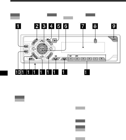
Location of controls
Refer to the pages listed for details.
TAPE : During tape playback RADIO : During radio reception MENU : During menu mode CD/MD : During CD/MD playback (optional) TV : During TV reception (optional)
a MBP button 16
bMENU button 8, 9, 10, 11, 12, 15, 16, 17, 19, 20, 21, 22
cVolume control dial
dLIST button
RADIO 11, 12
CD/MD 19, 20
eReceptor for the card remote commander
fSOURCE (Power on/Tape/Radio/CD/ MD/TV) button 5, 9, 10, 11, 16, 17, 19, 21, 22, 23
gDisplay window
hZ(eject) button (located on the front side of the unit, behind the front panel) 9, 23
iOPEN button 7, 9
jEQ7 button 16
kRESET button (located on the front side of the unit, behind the front panel) 7
lOFF (Stop/Power off) button* 5, 7, 9, 17
mFrequency select switch (located on the bottom of the unit)
(XR-CA620X only)
See “Frequency select switch” in the Installation/Connections manual.
nSOUND button 14, 16
o ENTER button
|
RADIO |
12 |
|
MENU |
8, 9, 10, 11, 12, 15, 16, 17, 19, |
|
|
20, 21, 22, 23 |
|
CD/MD |
19, 20 |
p |
MODE |
(o) button |
|
|
9 |
|
TAPE |
|
|
RADIO |
10, 11 |
|
CD/MD |
17, 19 |
|
TV |
21 |
qDSPL (display mode change) button
12, 18, 19
rNumber buttons
TAPE
(1) REP 9
RADIO 10, 11
CD/MD
(1)REP 18
(2)SHUF 18
TV 22
*Warning when installing in a car without an ACC (accessory) position on the ignition switch
After turning off the ignition, be sure to press (OFF) on the unit for 2 seconds to turn off the clock display.
Otherwise, the clock display does not turn off and this causes battery drain.
4
3
XR-CA600X/CA620X
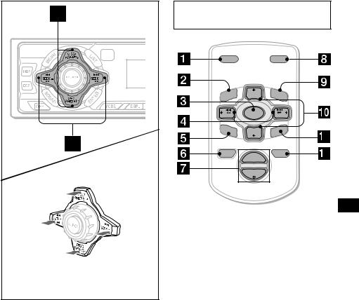
(DISC/PRESET)
(+): to select upwards
(SEEK)
(+):to select rightwards/
>
(SEEK)
(–): to select leftwards/
.
(DISC/PRESET)
(–): to select downwards
In menu mode, the currently selectable button (s) of these four are indicated with a “ M” in the display.
s DISC/PRESET buttons (+/–)
|
RADIO |
10, 11, 12 |
|
MENU |
8, 9, 10, 11, 12, 15, 16, 17, 19, |
|
|
20, 21, 22 |
|
CD/MD |
17, 19, 20 |
|
TV |
21 |
t |
SEEK |
buttons (–/+) |
|
|
9 |
|
TAPE |
|
|
RADIO |
10, 11 |
|
MENU |
8, 9, 14, 15, 16, 17, 21 |
|
CD/MD |
17, 19, 20 |
|
TV |
22, 23 |
Card remote commander RM-X114 (XR-CA620X only)
DSPL |
|
MODE |
|
PRESET + |
|
MEN |
DISC + |
LIST |
U |
|
|
SEEK– |
SOURCE |
SEEK+ |
|
||
SOUND |
DISC – |
ENTER |
|
PRESET – |
|
OFF |
+ |
ATT |
|
VOL |
|
|
– |
|
The corresponding buttons of the card remote commander control the same functions as those on this unit.
aDSPL button
bMENU button
cSOURCE button
dSEEK (</,) buttons
eSOUND button
fOFF button
gVOL (–/+) buttons
hMODE button
iLIST button
jDISC/PRESET(M/m) buttons
kENTER button
lATT button
Note
If the units is turned off by pressing (OFF) for 2 seconds, it cannot be operated with the card remote commander unless (SOURCE) on the unit is pressed, or a cassette is inserted to activate the unit first.
Tip
Refer to “Replacing the lithium battery” for details on how to replace the batteries (page 24).
5
4
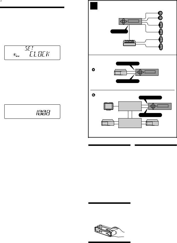
Setting the clock
The clock uses a 12-hour digital indication.
Example: To set the clock to 10:08
1 Press (MENU), then press either side of (DISC/PRESET) repeatedly until “CLOCK” appears.
1Press (ENTER).
The hour indication flashes.
2Press either side of (DISC/PRESET) to set the hour.
3Press the (+) side of (SEEK).
The minute indication flashes.
4Press either side of (DISC/PRESET) to set the minute.
2 Press (ENTER).
The clock starts. After the clock setting is completed, the display returns to normal play mode.
Tip
When D.INFO mode is set to ON, the time is always displayed (page 15).
|
XR-CA600X/CA620X |
|
2 |
|
|
A |
|
|
|
AUDIO OUT |
|
B |
BUS AUDIO IN |
|
|
BUS CONTROL IN |
|
|
|
BUS AUDIO IN |
|
TV tuner unit |
* |
|
Syntoniseur de télévision |
|
|
|
BUS CONTROL IN |
|
Source selector |
* |
|
Selector de fuente |
|
|
|
*not supplied |
|
|
no suministrado |
Cautions
•This unit is designed for negative earth 12 V DC operation only.
•Do not get the wires under a screw, or caught in moving parts (e.g. seat railing).
•Before making connections, disconnect the earth terminal of the car battery to avoid short circuits.
•Connect the yellow and red power input leads only after all other leads have been connected.
•Run all earth wires to a common earth point.
•Be sure to insulate any loose unconnected wires with electrical tape for safety.
Notes on the power supply cord (yellow)
•When connecting this unit in combination with other stereo components, the connected car circuit’s rating must be higher than the sum of each component’s fuse.
•When no car circuits are rated high enough, connect the unit directly to the battery.
Parts Iist (1)
The numbers in the list are keyed to those in the instructions.
Caution
Handle the bracket 1 carefully to avoid injuring your fingers.
Connection example (2)
Notes (2-A)
•Be sure to connect the earth cord before connecting the amplifier.
•If you connect an optional power amplifier and do not use the built-in amplifier, the beep sound will be deactivated.
Tip (2-B- )
)
For connecting two or more changers, the source selector XA-C30 (optional) is necessary.
Connection diagram (3)
1 To a metal surface of the car
First connect the black earth lead, then connect the yellow and red power input leads.
2 To the power aerial control lead or power supply lead of aerial booster amplifier
Notes
•It is not necessary to connect this lead if there is no power aerial or aerial booster, or with a manually-operated telescopic aerial.
•When your car has a built-in FM/MW/SW aerial in the rear/side glass, see “Notes on the control and power supply leads.”
3 To AMP REMOTE IN of an optional power amplifier
This connection is only for amplifiers. Connecting any other system may damage the unit.
4 To the +12 V power terminal which is energised in the accessory position of the ignition key switch
Notes
•If there is no accessory position, connect to the +12 V power (battery) terminal which is energised at all times.
Be sure to connect the black earth to it first.
•When your car has a built-in FM/MW/SW aerial in the rear/side glass, see “Notes on the control and power supply leads.”
5 To the +12 V power terminal which is energised at all times
Be sure to connect the black earth lead to it first.
Notes on the control and power supply leads
•The power aerial control lead (blue) supplies +12 V DC when you turn on the tuner.
•When your car has built-in FM/MW/SW aerial in the rear/side glass, connect the power aerial control lead (blue) or the accessory power input lead (red) to the power terminal of the existing aerial booster. For details, consult your dealer.
•A power aerial without relay box cannot be used with this unit.
Memory hold connection
When the yellow power input lead is connected, power will always be supplied to the memory circuit even when the ignition key is turned off.
Notes on speaker connection
•Before connecting the speakers, turn the unit off.
•Use speakers with an impedance of 4 to 8 ohms, and with adequate power handling capacities to avoid its damage.
•Do not connect the speaker terminals to the car chassis, or connect the terminals of the right speakers with those of the left speaker.
•Do not connect the earth lead of this unit to the negative (–) terminal of the speaker.
•Do not attempt to connect the speakers in parallel.
•Connect only passive speakers. Connecting active speakers (with built-in amplifiers) to the speaker terminals may damage the unit.
5
XR-CA600X/CA620X
3
Supplied with XA-C30 Suministrado con el XA-C30
Supplied with the CD/MD changer |
Source selector |
Suministrado con el cambiador de CD/MD |
Selector de fuente |
BUS AUDIO IN
3
Left
Izquierdo
Right
Derecho
Left
Izquierdo
Right
Derecho
|
L |
|
|
from car aerial adaptor |
R |
|
|
BUS |
AUDIO OUT AUDIO OUT |
||
de la antenna del automóvil |
|||
AUDIO |
REAR FRONT |
AUDIO OUT
RCA pin cord (not supplied) |
7 |
Cable con clavijas RCA (no suministrado) |
Blue/white striped |
|
|
|
Con raya azul/blanca |
AMP REM
Max. supply current 0.3 A
Corriente máx. de alimentación de 0,3 A
White
 Blanco
White/black striped
Con raya blanco/negro
Grey
 Gris
Gris
Grey/black striped
Con raya gris/negro
Green
 Verde
Verde
Green/black striped
Con raya verde/negro
Purple
 Púrpura
Purple/black striped
Con raya púrpura/negro
Fuse (10 A)
Fusible (10 A)
BUS CONTROL IN
REMOTE IN
Black
Negro
Blue
Azul
Insert with the cord upwards.
Insertar con el cable hacia arriba.
ANT REM
Max. supply current 0.1 A Corriente máx. de
alimentación de 0,1 A
Red
Rojo
Yellow
Amarillo
1
2
4
5
Precauciones
•Esta unidad ha sido diseñada para alimentarse con 12 V CC, negativo a masa, solamente.
•No coloque los cables debajo de ningún tornillo, ni los aprisione con partes móviles (p.ej. los raíles del asiento).
•Antes de realizar las conexiones, desconecte el terminal de puesta a masa de la batería del automóvil a fin de evitar cortocircuitos.
•Conecte los cables de entrada de alimentación amarillo y rojo solamente después de haber conectado los demás.
•Conecte todos los conductores de puesta a masa a un punto común.
•Por razones de seguridad, asegúrese de aislar con cinta eléctrica los cables sueltos que no estén conectados.
Notas sobre el cable de suministro de alimentación (amarillo)
•Cuando conecte esta unidad en combinación con otros componentes estéreo, la capacidad nominal del circuito conectado del automóvil debe ser superior a la suma de los fusibles de cada componente.
•Si no hay circuitos del automóvil con capacidad nominal suficientemente alta, conecte la unidad directamente a la batería.
Lista de componentes (1)
Los números de la lista corresponden a los de las instrucciones.
Precaución
Tenga mucho cuidado al manipular el soporte 1 para evitar posibles lesiones en los dedos.
Ejemplo de conexiones (2)
Notas (2-A)
•Asegúrese de conectar primero el cable de puesta a masa antes de realizar la conexión al amplificador.
•Si conecta un amplificador de potencia opcional y no utiliza el incorporado, los pitidos se desactivarán.
Consejo (2-B-  )
)
Cuando desee conectar dos o más cambiadores, necesitará un selector de fuente XA-C30 (opcional).
Diagramas de conexión (3)
1A una superficie metálica del automóvil
Conecte primero el cable de masa negro, y después los cables amarillo y rojo de entrada de alimentaciónpara obtener información detallada.
2Al cable de control de la antena motorizada o al cable de fuente de alimentación del amplificador de antena
Notas
•Si no se dispone de antena motorizada ni de amplificador de antena, o se utiliza una antena telescópica accionada manualmente, no será necesario conectar este cable.
•Si el automóvil incorpora una antena de FM/MW/SW en el cristal trasero/lateral, consulte “Notas sobre los cables de control y de fuente de alimentación.”
3Para conectar a AMP REMOTE IN del amplificador de potencia opcional
Esta conexión es sólo para amplificadores.
La conexión de cualquier otra sistema, puede dañar la unidad.
4Al terminal de alimentación de +12 V que recibe energía en la posición de accesorios del interruptor de la llave de encendido
Notas
•Si no hay posición de accesorios, conéctelo al terminal de alimentación (batería) de +12 V que recibe energía sin interrupción.
Asegúrese de conectar primero el cable de masa negro.
•Si el automóvil incorpora una antena de FM/MW/SW en el cristal trasero/lateral, consulte “Notas sobre los cables de control y de fuente de alimentación.”
5Al terminal de alimentación de +12 V que recibe energía sin interrupción
Asegúrese de conectar primero el cable de masa negro.
Notas sobre los cables de control y de fuente de alimentación
•El conductor de control de la antena motorizada (azul) suministrará +12 V CC cuando conecte la alimentación del sintonizador.
•Si el automóvil dispone de una antena de FM/MW/SW incorporada en el cristal trasero/lateral, conecte el cable de control de antena motorizada (azul) o el cable de entrada de alimentación auxiliar (rojo) al terminal de alimentación del amplificador de antena existente. Para obtener información detallada, consulte a su proveedor.
•Con esta unidad no es posible utilizar una antena motorizada sin caja de relé.
Conexión para protección de la memoria
Si conecta el conductor de entrada amarillo, el circuito de la memoria recibirá siempre alimentación, incluso aunque ponga la llave de encendido en la posición OFF.
Notas sobre la conexión de los altavoces
•Antes de conectar los altavoces, desconecte la alimentación de la unidad.
•Utilice altavoces con una impedancia de 4 a 8 ohmios con la capacidad de potencia adecuada para evitar que se dañen.
•No conecte los terminales de altavoz al chasis del automóvil, ni conecte los terminales del altavoz derecho con los del izquierdo.
•No conecte el cable de puesta a tierra de esta unidad al terminal negativo (–) del altavoz.
•No intente conectar los altavoces en paralelo.
•Conecte solamente altavoces pasivos. Si conecta altavoces activos (con amplificadores incorporados) a los terminales de altavoz, puede dañar la unidad.


 3
3
• |
1 |
• |
|
•2
• |
• |
• |
• |
|
•3 


• |
4 |
•
•
•
5


 1
1
•
•


 1
1 


•
|
2 |
• |
|
|
• |
|
2 |
• |
• |
|
|
|
|
•
•
•
•
2
6

XR-CA600X/CA620X
4 |
A |
B |
c
5 |
1 |
|
|
2 |
3 |
|
4 |
Fire wall |
|
|
|
|
|
|
|
|
Dashboard |
|
|
|
|
|
|
|
|
Salpicadero |
|
|
|
|
|
|
|
|
Panel cortafuegos |
|
|
182 |
m |
|
|
|
|
|
|
|
|
m |
|
|
|
|
1 |
|
|
|
|
|
|
|
|
|
|
|
|
53 |
mm |
4 |
5 4 |
6 |
2 |
|
|
|
|
|||||
|
|
|
|
Bend these claws outward |
|
|
|
|
1 |
|
|
|
for a tight fit, if necessary. |
|
|
|
|
|
|
|
|
Si es necesario, doble estas |
5 |
|
|
3 |
|
|
|
|
uñas hacia fuera para que |
|
|
||
|
|
|
|
encaje firmemente. |
|
|
|
|
5 4
Precautions
•Choose the installation location carefully so that the unit will not interfere with normal driving operations.
•Avoid installing the unit in areas subject to dust, dirt, excessive vibration, or high temperatures, such as in direct sunlight or near heater ducts.
•Use only the supplied mounting hardware for a safe and secure installation.
•There must be a distance of at least 15 cm between the cassette slot of the unit and shift lever in order to insert a cassette easily. Choose the installation location carefully so the unit does not interfere with gear shifting and other driving operations.
Mounting example (5)
Installation in the dashboard
Mounting the unit in a Japanese car (6)
You may not be able to install this unit in some makes of Japanese cars. In such a case, consult your Sony dealer.
Note
To prevent malfunction, install only with the supplied screws 4.
Precauciones
•Elija cuidadosamente el lugar de montaje de forma que la unidad no interfiera las funciones normales de conducción.
•Evite instalar la unidad donde pueda quedar sometida a altas temperaturas, como a la luz solar directa o al aire caliente de calefacción, o a polvo, suciedad, o vibraciones excesivas.
•Para realizar una instalación segura y firme, utilice solamente la ferretería de montaje suministrada.
•Para que sea posible insertar cassettes con facilidad, debe haber una distancia de al menos 15 cm entre la ranura de inserción de cassettes de la unidad y la palanca de cambios. Elija cuidadosamente el lugar de instalación de forma que la unidad no entorpezca las operaciones de cambio de marchas o de conducción en general.
Ejemplo de montaje (5)
Instalación en el salpicadero
Montaje de la unidad en un automóvil japon és (6)
Usted no podrá instalar esta unidad en algunos automóviles japoneses. En tal caso, consulte a su proveedor Sony.
Nota
Para evitar que se produzcan fallos, realice la instalación solamente con los tornillos suministrados
4.
Warning when installing in a car
15 cm |
without ACC (accessory) |
|
|
||
|
position on the ignition key |
|
|
switch |
|
|
Be sure to press(OFF) on the unit for two |
|
|
seconds to turn off the clock display after |
|
Mounting angle adjustment |
turning off the engine. |
|
When you press (OFF) only momentarily, the |
||
Adjust the mounting angle to less than 20° . |
||
clock display does not turn off and this causes |
||
|
||
|
battery wear. |
How to detach and attach the front panel (4)
Before installing the unit, detach the front panel.
4-A To detach
Before detaching the front panel, be sure to press (OFF). Press (OPEN), then slide the front panel to the right side, and pull out the left side.
4-B To attach
Place the hole  in the front panel onto the spindle
 on the unit as illustrated, then push the left side in.
Frequency select switch (XR-CA620X)
The MW (FM) tuning interval is factory-set to the 10 k (200 k) position. If the frequency allocation system of your country is based on 9 kHz (50 kHz) interval, set the switch on the bottom of the unit to the 9 k (50 k) position before making connections.
RESET button
When the installation and connections are completed, be sure to press the RESET button with a ballpoint pen, etc.
15 cm
Ajuste del ángulo de montaje
Ajuste el ángulo de montaje a menos de 20° .
Advertencia sobre la instalaci ón en un automóvil que no disponga de posición ACC (accesorios) en el interruptor de la llave de encendido
Asegúrese de pulsar (OFF) en la unidad durante dos segundos para desactivar la indicación del reloj después de apagar el motor.
Si pulsa (OFF) sólo momentáneamente, la indicación del reloj no se desactivará y esto causará el desgaste de la batería.
Forma de extraer e instalar el panel frontal (4)
Antes de instalar la unidad, extraiga el panel frontal.
4-A Para extraerlo
Antes de extraer el panel frontal, ceriórese de presionar (OFF). Después presione (OPEN) a fin de abrirlo, después deslícelo hacia la derecha, y por último tire de su parte izquierda.
4-B Para instalarlo
Coloque el orificio |
del panel frontal en el eje |
de la unidad, como se muestra en la ilustración, y después presione la parte izquierda.
Botón RESET
Cuando finalice la instalación y las conexiones, cerciórese de pulsar el botón RESET con un bolígrafo, etc.
Selector de frecuencia (XR-CA620X)
El intervalo de sintonía de MW (FM) ha sido ajustado en fábrica a la posición 10 k (200 k). Si el sistema de asignación de frecuencias de su país se basa en el intervalo de 9 kHz (50 kHz), ponga este selector, situado en la base de la unidad, en la posición 9 k (50 k) antes de realizar las conexiones.
7
XR-CA600X/CA620X
6 A |
|
B |
|
|
TOYOTA |
|
NISSAN |
|
|
4 |
|
4 |
|
|
|
max. size |
|
||
max. size |
|
|
||
to dashboard/center console |
5 × 8 mm |
to dashboard/center console |
||
5 × 8 mm |
||||
al salpicadero/consola central |
Tamaño máx. |
al salpicadero/consola central |
||
Tamaño máx. |
||||
|
M5 × 8 mm |
|
||
M5 × 8 mm |
|
|
||
|
|
|
Bracket |
4 |
Bracket |
4 |
|
Soporte |
max. size |
max. size |
||
Soporte |
||||
|
5 × 8 mm |
5 × 8 mm |
||
|
|
|||
|
Tamaño máx. |
|
Tamaño máx. |
|
|
M5 × 8 mm |
|
M5 × 8 mm |
|
Bracket |
|
Bracket |
|
|
Soporte |
|
|
||
|
Soporte |
|
||
|
|
|
||
Existing parts supplied with your car |
|
Existing parts supplied with your car |
|
|
Piezas existentes suministradas con su automóvil |
|
Piezas existentes suministradas con su automóvil |
|


 5
5
•
•
•
• |
6 |
|


 4
4
15 cm
(OFF) 


 (OFF)
(OFF)


 4
4
4


 (OFF)
(OFF) 


(OPEN)
4

(XR-CA620X)
8
XR-CA600X/CA620X
SECTION 2
DISASSEMBLY
• This set can be disassembled in the order shown below.
2-1. DISASSEMBLY FLOW
SET
FRONT PANEL SECTION
Note: Illustration of disassembly is omitted.
2-2. SUB PANEL ASSY (Page 9)
2-3. MECHANISM DECK (MG-25F-136) (Page 10)
2-4. MAIN BOARD
(Page 10)
2-5. HEAT SINK (2P) (Page 11)
Note: Follow the disassembly procedure in the numerical order given.
2-2. SUB PANEL ASSY
1 screw (PTT2.6 × 5)
 2 cover
4 two claws
6 sub panel assy
3 screw (PTT2.6 × 6)
3 two screws |
5 flexible flat (14core) cable |
||
(CN701) |
|
||
(PTT2.6 × |
6) |
|
|
|
|
||
|
|
3 screw (PTT2.6 × |
4 claw |
|
|
6) |
|
9
XR-CA600X/CA620X
2-3. MECHANISM DECK (MG-25F-136)
3 screw (PTT2.6 × 6)
4 mechanism deck (MG-25F-136)
2connector (CN351)
 1 flexible board (CN301)
2-4. MAIN BOARD
3 rubber cap (25)
1 three screws
(PTT2.6 × 8)
2 three ground point
screws
4 main board
10
XR-CA600X/CA620X
2-5. HEAT SINK (2P)
1 three screws
(PTT2.6 × |
8) |
|
2 two screws |
3 heat sink (2P) |
(PTT2.6 × 12) |
|
1 two screws |
|
(PTT2.6 × 8) |
11
Loading...