


XR-H572A

XR-H572A/H572W/H572WT/
H573A/H573W
THIS NOTE IS COMMON FOR PRINTED WIRING BOARDS
AND SCHEMATIC DIAGRAMS.
(In addition to this, the necessary note is
printed in each block.)
SECTION 1
DIAGRAMS
SERVICE MANUAL
SUPPLEMENT-1
File this supplement with the service manual.
Subject : Change of Main Board
When performing service and inspection, check the part number
of the main board.
– MAIN BOARD (SIDE A) –
(ECN-CSB00374)
• For printed wiring boards.
• X : parts extracted from the component side.
®
•
•
• b : Pattern from the side which enables seeing.
• (( )) : Page of service manual.
Caution:
Pattern face side: Parts on the pattern face side seen from the
(Side B) pattern face are indicated.
Parts face side: Parts on the parts face side seen from the
(Side A) parts face are indicated.
: Through hole.
¢
: internal component.
: Chip transistor of abbreviation (E, C, B)
BCE
• For schematic diagrams.
• All capacitors are in µF unless otherwise noted. pF: µµF
50 WV or less are not indicated except for electrolytics
and tantalums.
• All resistors are in Ω and 1/
specified.
• % : indicates tolerance.
¢
•
• C : panel designation.
• U : B+ Line.
• H : adjustment for repair.
• Power voltage is dc 14.4V and fed with regulated dc power
• Voltage is dc with respect to ground under no-signal
• Voltages are taken with a V OM (Input impedance 10 MΩ).
• Signal path.
• (( )) : Page of service manual.
: internal component.
supply from ACC and BATT cords.
(detuned) condition.
no mark : FM
(): AM
< > : PB
Voltage variations may be noted due to normal production tolerances.
F : FM
f : AM
E : PB
<< >> : Page of supplement-1.
: Impossible to measure.
∗
4
W or less unless otherwise
Main board Part No.
Former :1-671-224-11
New :1-674-279-11
– 2 –
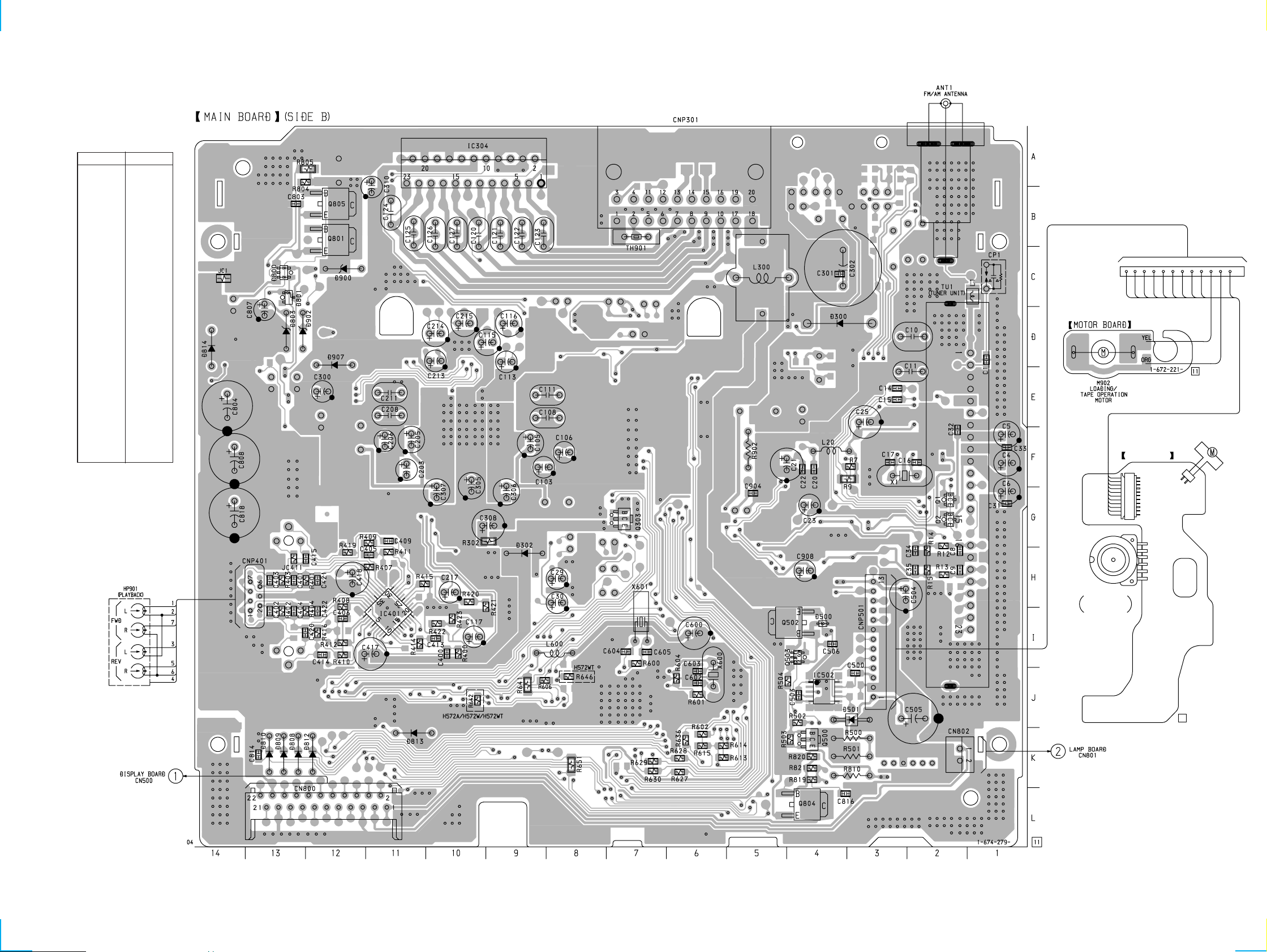
• Semiconductor
Location (Side B)
Ref. No. Location
D300 D-4
D302 H-9
D500 I-4
D501 J-3
D800 C-13
D801 C-13
D803 D-13
D808 J-13
D809 J-13
D810 J-13
D812 J-12
D813 K-11
D814 D-14
D900 C-12
D902 D-13
D907 D-12
IC304 A-10
IC401 I-11
IC502 J-4
XR-H572A/H572W/H572WT/H573A/H573W
113
YEL
GRY
GRY
GRY
GRY
GRY
GRY
GRY
GRY
GRY
ORG
Q1 G-2
Q2 G-2
Q303 G-7
Q500 K-4
Q502 I-4
Q503 I-4
Q801 B-12
Q804 L-4
RED
S901
TAPE OPERATION
ROTARY SLIDE
SWITCH
REEL BOARD
12
M901
CAPSTAN/REEL
MOTOR
RED
BLK
((Page 28))
– 5 – – 6 –
((Page 27))
1–670–227–
11
 Loading...