


 Loading...
XR-CA600/CA600V/CA600X
SERVICE MANUAL |
AEP Model |
Ver 1.0 2001.02 |
UK Model |
|
Photo: XR-CA600X
Model Name Using Similar Mechanism |
XR-C5300R |
|
|
Tape Transport Mechanism Type |
MG-25G-136 |
SPECIFICATIONS
Cassette Player section
Tape track |
|
4-track 2-channel stereo |
|
Wow and flutter |
0.08 % (WRMS) |
|
|
Frequency response |
30 – 18,000 Hz |
|
|
Signal-to-noise ratio |
|
|
|
|
|
Cassette type |
|
|
|
|
|
|
|
TYPE II, IV |
61 dB |
|
|
|
|
|
|
TYPE I |
58 dB |
Tuner section |
|
|
|
|
|
||
FM |
|
|
|
Tuning range |
87.5 – 108.0 MHz |
|
|
Aerial terminal |
External aerial connector |
||
Intermediate frequency |
10.7 MHz/450 kHz |
||
Usable sensitivity |
8 dBf |
|
|
Selectivity |
|
75 dB at 400 kHz |
|
Signal-to-noise ratio |
66 dB (stereo), |
|
|
|
|
72 dB (mono) |
|
Harmonic distortion at 1 kHz |
|
||
|
|
0.6 % (stereo), |
|
|
|
0.3 % (mono) |
|
Separation |
|
35 dB at 1 kHz |
|
Frequency response |
30 – 15,000 Hz |
|
|
MW/LW |
|
|
|
Tuning range |
MW: 531 – 1,602 kHz |
||
|
|
LW: 153 – 279 kHz |
|
Aerial terminal |
External aerial connector |
||
Intermediate frequency |
10.7 MHz/450 kHz |
||
Sensitivity |
|
MW: 30 µ V |
|
|
|
LW: 40 µ V |
|
Power amplifier section |
|
||
Outputs |
|
Speaker outputs |
|
|
|
(sure seal connectors) |
|
Speaker impedance |
4 – 8 ohms |
|
|
Maximum power output |
50 W × 4 (at 4 ohms) |
||
9-870-246-11 |
Sony Corporation |
|
|
2001B0500-1 |
Audio Entertainment Group |
||
C 2001.2 |
General Engineering Dept. |
|
|
General
Outputs |
Audio outputs (Rear) |
|
|
|
Power aerial relay control |
||
|
lead |
|
|
|
Power amplifier control lead |
||
Inputs |
Telephone ATT control lead |
||
|
BUS control input |
|
|
|
connector |
|
|
|
BUS audio input connector |
||
|
Remote controller input |
||
|
connector |
|
|
|
Aerial input connector |
||
Tone controls |
Bass ± 8 dB at 100 Hz |
||
|
Treble ± 8 dB at 10 kHz |
||
Loudness |
100 Hz +8 dB |
|
|
|
10 kHz +2 dB |
|
|
Power requirements |
12 V DC car battery |
|
|
|
(negative earth) |
|
|
Dimensions |
Approx. 178 × |
50 × |
176 |
|
mm (w/h/d) |
|
|
Mounting dimensions |
Approx. 182 × |
53 × |
161 |
|
mm (w/h/d) |
|
|
Mass |
Approx. 1.2 kg |
|
|
Supplied accessories |
Parts for installation and |
||
|
connections (1 set) |
|
|
|
Front panel case (1) |
|
|
Note
This unit cannot be connected to a digital preamplifier or an equalizer.
Design and specifications are subject to change without notice.
FM/MW/LW CASSETTE CAR STEREO
XR-CA600/CA600V/CA600X
TABLE OF CONTENTS |
|
1. GENERAL |
|
Location of Controls ....................................................... |
3 |
Setting the Clock ............................................................. |
4 |
2.DISASSEMBLY
2-1. |
Disassembly Flow ........................................................... |
8 |
2-2. |
Mechanism Deck (MG-25G-136) ................................... |
8 |
2-3. |
MAIN Board ................................................................... |
9 |
2-4. |
Heat Sink (ISO2P) .......................................................... |
9 |
3.ASSEMBLY OF MECHANISM DECK
3-1. |
Housing ........................................................................... |
10 |
3-2. |
Arm (Suction) ................................................................. |
10 |
3-3. |
Lever (LDG-A)/(LDG-B) ............................................... |
11 |
3-4. |
Gear (LDG-FT) ............................................................... |
11 |
3-5. |
Guide (C) ......................................................................... |
12 |
3-6. Mounting Position of Capstan/Reel Motor (M901) ....... |
12 |
|
4. |
MECHANICAL ADJUSTMENTS ....................... |
13 |
5.ELECTRICAL ADJUSTMENTS
Tape Deck Section .......................................................... |
13 |
Tuner Section .................................................................. |
13 |
6.DIAGRAMS
6-1. |
Note for Printed Wiring Boards and |
|
|
Schematic Diagrams ....................................................... |
14 |
6-2. |
Printed Wiring Board – MAIN Board – ......................... |
15 |
6-3. |
Schematic Diagram – MAIN Board (1/3) – ................... |
16 |
6-4. |
Schematic Diagram – MAIN Board (2/3) – ................... |
17 |
6-5. |
Schematic Diagram – MAIN Board (3/3) – ................... |
18 |
6-6. |
Printed Wiring Board – SUB Board – ............................ |
19 |
6-7. |
Schematic Diagram – SUB Board – ............................... |
19 |
6-8. |
Printed Wiring Board |
|
|
– KEY Board (XR-CA600/CA600X) – ......................... |
20 |
6-9. |
Printed Wiring Board |
|
|
– KEY Board (XR-CA600V) – ...................................... |
21 |
6-10. |
Schematic Diagram – KEY Board – .............................. |
22 |
6-11. IC Pin Function Description ........................................... |
26 |
|
7.EXPLODED VIEWS
7-1. |
General Section ............................................................... |
29 |
7-2. |
Front Panel Section ......................................................... |
30 |
7-3. |
Mechanism Deck Section (MG-25G-136) ..................... |
31 |
8. |
ELECTRICAL PARTS LIST ............................... |
32 |
Notes on chip component replacement
•Never reuse a disconnected chip component.
•Notice that the minus side of a tantalum capacitor may be damaged by heat.
Flexible Circuit Board Repairing
•Keep the temperature of the soldering iron around 270 ˚C during repairing.
•Do not touch the soldering iron on the same conductor of the circuit board (within 3 times).
•Be careful not to apply force on the conductor when soldering or unsoldering.
2
SECTION 1
GENERAL
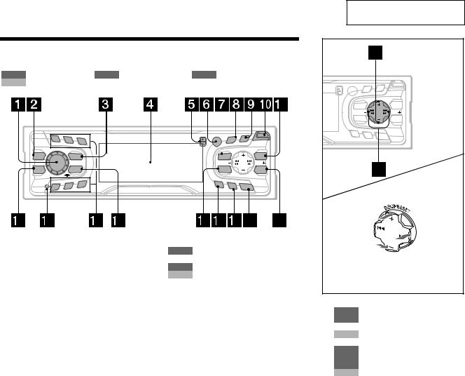
Location of controls
Refer to the pages listed for details.
TAPE : During tape playback RADIO : During radio reception MENU : During menu mode
CD/MD : During CD/MD playback (optional)
XR-CA600/CA600V/CA600X
This section is extracted from instruction manual.
PTY |
|
S |
|
|
|
D |
|
|
OPEN |
||
DISPLAY |
SCROLL |
||||
|
R |
|
|
|
|
|
|
|
|
|
|
|
/P E |
|
|
||
|
ISC |
|
SE |
|
|
D |
|
|
T |
|
|
MENU |
|
|
|
|
LIST |
SEEK |
|
|
|
|
SEEK |
SOUND |
|
|
|
|
ENTER |
1 |
2 |
3 |
PTY |
|
S |
|
|
|
D |
|
|
OPEN |
|||||
|
|
REP |
DISPLAY |
SCROLL |
|
|||
|
|
|
R |
|
|
|
||
|
|
|
|
|
|
|
||
|
|
|
|
/P E |
|
|
||
|
|
|
|
ISC |
|
SE |
|
|
|
|
|
|
D |
|
|
T |
|
MBP |
|
SOURCE |
MENU |
|
|
|
|
LIST |
|
|
|
SEEK |
|
|
|
|
SEEK |
EQ 7 |
|
MODE |
SOUND |
|
|
|
|
ENTER |
|
|
SHUF |
|
|
|
|
|
|
4 |
5 |
6 |
AF |
TA |
OFF |
|
|||||
|
|
a Volume control dial 13 b MBP button 19
cSOURCE (Power on/Tape/Radio/CD/ MD) button 5, 9, 10, 11, 13, 19, 20, 22
dDisplay window
eZ(eject) button (located on the front side of the unit, behind the front panel) 9
fReceptor for the card remote commander
gMENU button 8, 9, 10, 14, 15, 18, 19, 20, 22, 23, 24
hDISPLAY/PTY (display mode change/ programme type) button 12, 15, 21, 22
iSCROLL button 21
jOPEN button 7, 9
kLIST button
RADIO |
11 |
CD/MD |
22, 23 |
l EQ7 button 19
mRESET button (located on the front side of the unit, behind the front panel) 7
n Number buttons
TAPE
(3) REP 9
RADIO 10, 11, 13, 14
CD/MD
(3) REP 21
(6) SHUF 21
o MODE (o) button
TAPE |
9 |
RADIO |
10, 11, 13 |
CD/MD |
20, 22 |
p SOUND button 17, 19 q AF button 12, 14
r TA button 13, 14
sOFF (Stop/Power off) button* 5, 7, 9, 20
tENTER button
RADIO |
11, 14 |
MENU |
8, 9, 10, 15, 18, 19, 20, 22, 23, |
|
24 |
CD/MD |
22, 23 |
*Warning when installing in a car without an ACC (accessory) position on the ignition switch
After turning off the ignition, be sure to press (OFF) on the unit for 2 seconds to turn off the clock display.
Otherwise, the clock display does not turn off and this causes battery drain.
AF |
TA |
OFF |
|
|
(DISC/PRESET)/(PRESET)
(+): to select upwards
(SEEK) |
(SEEK) |
(–): to select |
(+): to select |
leftwards/ |
rightwards/ |
.
 >
>
(DISC/PRESET)/(PRESET)
(–): to select downwards
In menu mode, the currently selectable button (s) of these four are indicated with a “ M” in the display.
uDISC/PRESET buttons (+/–)
RADIO 10, 11, 15
MENU 8, 9, 10, 14, 15, 18, 19, 20, 22, 23, 24
CD/MD 20, 22, 23 v SEEK buttons (–/+)
TAPE |
9 |
RADIO |
10, 11, 13 |
MENU |
8, 9, 15, 17, 18, 19, 20, 24 |
CD/MD |
20, 22, 23 |
3
XR-CA600/CA600V/CA600X
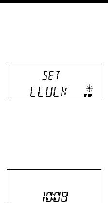
Setting the clock
The clock uses a 24-hour digital indication.
Example: To set the clock to 10:08
1 Press (MENU), then press either side of (DISC/PRESET) or (PRESET) repeatedly until “CLOCK” appears.
1Press (ENTER).
The hour indication flashes.
2Press either side of (DISC/PRESET) or (PRESET) to set the hour.
3Press the (+) side of (SEEK).
The minute indication flashes.
4Press either side of (DISC/PRESET) or (PRESET) to set the minute.
2 Press (ENTER).
The clock starts. After the clock setting is completed, the display returns to normal play mode.
Tips
•You can set the clock automatically with the RDS feature (page 15).
•When D.INFO mode is set to ON, the time is always displayed (page 18).
4
XR-CA600/CA600V/CA600X
2
A
AUDIO OUT
B |
XR-CA600X/CA600V/CA600 only |
Nur XR-CA600X/CA600V/CA600 |
|
|
XR-CA600X/CA600V/CA600 seulement |
|
Solo XR-CA600X/CA600V/CA600 |
|
Alleen voor de XR-CA600X/CA600V/CA600 |
|
BUS AUDIO IN |
|
BUS CONTROL IN |
|
AUDIO OUT |
|
BUS AUDIO IN |
|
Source selector * |
|
Signalquellenwähler |
|
Sélecteur de source |
|
Selettore di fonte |
|
Geluidsbronkiezer |
|
BUS CONTROL IN |
|
*not supplied |
|
nicht mitgeliefert |
|
non fourni |
|
non in dotazione |
|
niet bijgeleverd |
3
RCA pin cord (not supplied) |
|
|
|
||
Cinchkabel (nicht mitgeliefert) |
|
|
Fuse (10 A) |
||
Cordon à broche RCA (non fourni) |
BUS AUDIO |
||||
Sicherung (10 A) |
|||||
Cavo a piedini RCA (non in dotazione) |
IN |
|
Fusible (10 A) |
||
Tulpstekkersnoer (niet bijgeleverd) |
|
|
Fusibile (10 A) |
||
|
|
|
|
Zekering (10 A) |
|
from car aerial* |
7 |
|
|
|
|
von Autoantenne* |
|
|
|
|
|
de l’antenne de la voiture* |
|
|
IN |
REAR |
|
|
|
|
BUS AUDIO AUDIO OUT |
||
dall’antenna dell’auto* |
|
|
|
|
|
van een auto-antenne* |
AUDIO OUT REAR |
|
|||
|
|
||||
|
|
REMOTE IN |
|
||
Insert with the cord upwards. |
|
|
|
||
Mit dem Kabel nach oben einsetzen! |
|
8 |
|||
Insérez avec le câble vers le haut. |
|
|
|||
Inserire con il cavo rivolto verso l’alto. |
|
|
|||
Inbrengen met het snoer naar boven. |
Blue/white striped |
||||
|
|
|
Blau-weiß gestreift |
||
|
|
|
Rayé bleu/blanc |
||
|
|
AMP REM |
A strisce blu e bianche |
||
Max. supply current 0.3 A |
A |
Blauw/wit gestreept |
|||
|
|
|
|
||
max. Versorgungsstrom 0,3 A |
|
|
|
|
|
Courant max. fourni 0,3 A |
|
|
|
|
|
Alimentazione massima fornita 0,3 A |
|
|
|
||
Max. voedingsstroom 0,3 A |
|
|
|
Light blue |
|
|
|
|
|
||
|
|
|
|
Hellblau |
|
|
|
|
|
Bleu ciel |
|
|
|
|
|
Azzurro |
|
|
B |
ATT |
|
Hemelsblauw |
|
|
|
|
|
||
|
Source selector |
|
|
(not supplied) |
|
|
Signalquellenwähler |
|
|
(nicht mitgeliefert) |
Supplied with the CD/MD changer |
|
Sélecteur de source |
Mit dem CD/MD-Wechsler geliefert |
|
(non fourni) |
Fourni avec le changeur de CD/MD |
|
Selettore di fonte |
In dotazione con il cambia CD/MD |
|
Geleverd met de CD/MD-wisselaar |
|
|
(non in dotazione) |
|
|
|
|
|
Geluidsbronkiezer |
|
|
(niet bijgeleverd) |
|
BUS CONTROL |
XA-C30 |
|
IN |
|
|
Supplied with XA-C30
Mit dem XA-C30 geliefert
Fourni avec le XA-C30
In dotazione con il modello XA-C30
Geleverd met de XA-C30
Power connecting |
cord (supplied with only South European model) |
|
|
|
|
|||||
Stromversorgungskabel |
|
|
|
|
|
|
|
|||
Cordon |
d’alimention |
|
|
|
|
|
5 |
7 |
||
Cavo di |
alimentazione |
|
|
|
|
|
||||
Voedingskabel |
|
|
|
|
|
|
||||
|
|
|
|
|
|
|
|
|||
|
|
|
|
|
|
|
|
|
|
|
|
|
|
|
from the car’s power connector |
|
|
|
|
|
|
|
|
|
|
vom Stromanschluß des Fahrzeugs |
|
|
|
|
|
|
|
|
|
|
du connecteur d’alimentation de la voiture |
|
|
||||
|
|
|
|
van de autovoedingsstekker |
|
|
|
|
|
|
|
|
|
|
dal connettore di alimentazione dell’auto |
4 |
8 |
||||
|
|
|
|
|
|
|
|
|
||
|
|
|
|
|
|
|
|
|
|
|
|
|
|
Yellow |
continuous power supply |
|
|
Red |
|
switched power supply |
|
|
|
|
Gelb |
permanente Stromversorgung |
|
|
Rot |
|
geschaltete Stromversorgung |
|
|
4 |
Jaune |
alimentation continue |
7 |
|
Rouge |
|
alimentation commutée |
||
|
|
|
Giallo |
alimentazione continua |
|
|
Rosso |
|
alimentazione commutata |
|
|
|
|
Geel |
continu voeding |
|
|
Rood |
|
geschakelde voeding |
|
|
|
|
Blue |
power aerial control |
|
|
Black |
|
earth |
|
|
|
|
Blau |
Motorantenne |
|
|
Schwarz |
|
Masse |
|
|
5 |
Bleu |
antenne électrique |
8 |
|
Noir |
|
masse |
|
|
|
|
|
Blu |
comando dell’antenna elettrica |
|
|
Nero |
|
terra |
|
|
|
|
Blauw |
automatische antenne |
|
|
Zwart |
|
aarding |
|
|
|
|
|
|
|
|
|
|
|
|
Positions 1, 2, 3 and 6 do not have pins.
An Position 1, 2, 3 und 6 befinden sich keine Stifte.
Les positions 1, 2, 3 et 6 ne comportent pas de broches.
Le posizioni 1, 2, 3 e 6 non hanno piedini.
De posities 1, 2, 3 en 6 hebben geen pins.
* Note for the aerial connecting |
* Nota per il collegamento dell’antenna |
If your car aerial is an ISO (International |
Se la vostra antenna della macchina è di |
Organisation for Standardisation) type, use |
tipo ISO (International Organization |
the supplied adaptor 7 to connect it. |
Standardization), utilizzare l’adattatore |
First connect the car aerial to the supplied |
7 in dotazione per collegarla. |
adaptor, then connect it to the aerial jack |
Collegare prima l’antenna della macchina |
of the master unit. |
all’adattatore in dotazione, quindi |
* Hinweis zum Anschließen der Antenne |
collegarla alla presa dell’antenna |
Wenn Ihre Fahrzeugantenne der ISO-Norm |
dell’apparecchio principale. |
(ISO = International Organization for |
* Opmerking bij de antenne-aansluiting |
Standardization - Internationale |
Indien uw wagen is uitgerust met een |
Normungsgemeinschaft) entspricht, schließen |
antenne van het type ISO (International |
Sie sie mit Hilfe des mitgelieferten Adapters 7 |
Organisation for Standardization), moet |
an. |
u die aansluiten met behulp van de |
Verbinden Sie zuerst die Fahrzeugantenne mit |
meegeleverde adaptor 7. |
dem mitgelieferten Adapter, und verbinden |
Sluit eerst de auto-antenne aan op de |
Sie diesen dann mit der Antennenbuchse des |
meegeleverde adaptor en vervolgens de |
Hauptgeräts. |
antennestekker op het hoofdtoestel. |
*Remarque sur le raccordement de l’antenne
Si votre antenne de voiture est de type ISO (organisation internationale de normalisation), utilisez l’adaptateur fourni 7 pour la raccorder.
Raccordez d’abord l’antenne de voiture à l’adaptateur fourni et, ensuite, à la prise d’antenne de l’appareil principal.
|
|
|
|
|
|
|
|
|
|
1 |
3 |
5 |
7 |
|
|
|
|
|
|
|
|
|
|
|
|
|
|
|
|
|
|
|
|
from the car’s speaker connector |
|
|
|
|
|
|
|
|
||
|
|
|
|
vom Lautsprecheranschluß des Fahrzeugs |
|
|
|
|
|
|
|
|||
|
|
|
|
du connecteur de haut-parleur de la voiture |
|
|
|
|
|
|||||
|
|
|
|
dal connettore del diffusore dell’auto |
|
|
|
|
|
|||||
|
|
|
|
van de autoluidsprekerstekker |
|
|
|
2 |
4 |
6 |
8 |
|||
|
|
|
|
|
|
|
|
|
|
|||||
|
|
|
|
|
|
|
|
|
|
|
|
|||
|
|
|
|
Speaker, Rear, Right |
|
|
|
|
|
Speaker, Front, Left |
|
|||
|
|
+ |
Lautsprecher hinten rechts |
|
|
|
+ |
|
Lautsprecher vorne links |
|||||
1 |
Purple |
|
haut-parleur, arrière, droit |
5 |
|
|
|
haut-parleur, avant, gauche |
||||||
|
|
Diffusore, posteriore, destro |
|
|
White |
|
|
Diffusore, anteriore, sinistro |
||||||
|
Violett |
|
|
Luidspreker, achter, rechts |
|
|
Weiß |
|
|
Luidspreker, voor, links |
||||
|
Mauve |
|
|
Speaker, Rear, Right |
|
|
Blanc |
|
|
Speaker, Front, Left |
|
|||
|
Viola |
|
|
|
|
Bianco |
|
|
|
|||||
2 |
Paars |
|
Lautsprecher hinten rechts |
|
|
Wit |
|
|
Lautsprecher vorne links |
|||||
|
– |
|
haut-parleur, arrière, droit |
6 |
|
|
– |
|
haut-parleur, avant, gauche |
|||||
|
|
|
Diffusore, posteriore, destro |
|
|
|
|
|
Diffusore, anteriore, sinistro |
|||||
|
|
|
|
Luidspreker, achter, rechts |
|
|
|
|
|
Luidspreker, voor, links |
||||
|
|
|
|
Speaker, Front, Right |
|
|
|
|
|
Speaker, Rear, Left |
|
|||
3 |
|
|
|
Lautsprecher vorne rechts |
7 |
|
|
|
|
Lautsprecher hinten links |
||||
|
+ |
|
haut-parleur, avant, droit |
|
|
+ |
|
haut-parleur, arrière, gauche |
||||||
|
Grey |
|
Diffusore, anteriore, destro |
|
|
Green |
|
|
Diffusore, posteriore, sinistro |
|||||
|
Grau |
|
|
Luidspreker, voor, rechts |
|
|
Grün |
|
|
Luidspreker, achter, links |
||||
|
Gris |
|
|
Speaker, Front, Right |
|
|
Vert |
|
|
Speaker, Rear, Left |
|
|||
|
Grigio |
|
|
|
|
Verde |
|
|
|
|||||
4 |
Grijs |
|
|
Lautsprecher vorne rechts |
|
|
Groen |
|
|
Lautsprecher hinten links |
||||
|
– |
|
haut-parleur, avant, droit |
8 |
|
|
– |
|
haut-parleur, arrière, gauche |
|||||
|
|
|
Diffusore, anteriore, destro |
|
|
|
|
|
Diffusore, posteriore, sinistro |
|||||
|
|
|
|
Luidspreker, voor, rechts |
|
|
|
|
|
Luidspreker, achter, links |
||||
|
|
|
|
|
|
|
|
|
|
|
|
|
|
|
Negative polarity positions 2, 4, 6, and 8 have striped cords.
An den negativ gepolten Positionen (2, 4, 6 und 8) befinden sich gestreifte Adern.
Les positions de polarité négative 2, 4, 6 et 8 sont dotées de cordons rayés.
Le posizioni a polarità negativa 2, 4, 6 e 8 hanno cavi rigati.
De negatieve posities 2, 4, 6 en 8 hebben gestreepte kabels.
5
XR-CA600/CA600V/CA600X
Cautions
• This unit is designed for negative earth 12 V DC operation only.
• Do not get the wires under a screw, or caught in moving parts (e.g. seat railing).
• Before making connections, turn the car ignition off to avoid short circuits.
• Connect the power connecting cord (not supplied) to the unit and speakers before connecting it to the auxiliary power connector.
• Run all earth wires to a common earth point.
• Be sure to insulate any loose unconnected wires with electrical tape for safety.
Notes on the power supply cord (yellow)
• When connecting this unit in combination with other stereo components, the connected car circuit’s rating must be higher than the sum of each component’s fuse.
• When no car circuits are rated high enough, connect the unit directly to the battery.
Power connection
Power connectors may vary depending on the car. Check your car’s power connector diagram to make sure the connections match correctly. There are two basic types. You may need to switch the positions of the jump connector. Before connecting the unit to the car’s power supply, be sure to match the position of the jump connector to the car’s pin order. If the power connector of your car does not match the connector on the unit, use the connector (not supplied). If you have any questions or problems connecting your unit that are not covered in this manual, please consult the car dealer.
WARNING
Shifting the fuse
Check the pin position of the power connector of the car with the table on the below. If positions 4 and 7 are reversed, remove the fuse and shift it to the lower position as shown in the illustration.
Vorsicht
• Dieses Gerät ist ausschließlich für den Betrieb bei 12 V Gleichstrom (negative Erdung) bestimmt.
• Achten Sie darauf, daß die Kabel nicht unter einer Schraube oder zwischen beweglichen Teilen wie z. B. in einer Sitzschiene eingeklemmt werden.
• Schalten Sie, bevor Sie irgendwelche Anschlüsse vornehmen, die Zündung des Fahrzeugs aus, um Kurzschlüsse zu vermeiden.
• Verbinden Sie das Stromversorgungskabel (nicht mitgeliefert) mit dem Gerät und den Lautsprechern, bevor Sie es mit dem Hilfsstromanschluß verbinden.
• Schließen Sie alle Erdungskabel an einen gemeinsamen
Massepunkt an.
• Aus Sicherheitsgründen müssen alle losen, nicht angeschlossenen Drähte mit Isolierband abisoliert werden.
Hinweise zum Stromversorgungskabel (gelb)
• Wenn Sie dieses Gerät zusammen mit anderen Stereokomponenten anschließen, muß der Autostromkreis, an den die Geräte angeschlossen sind, eine höhere Leistung aufweisen als die Summe der Sicherungen der einzelnen Komponenten.
• Wenn kein Autostromkreis eine so hohe Leistung aufweist, schließen Sie das Gerät direkt an die Batterie an.
Stromanschluß
Die Stromanschlüsse verschiedener Fahrzeuge können sich voneinander unterscheiden. Überprüfen Sie anhand des Stromanschluß-Schaltplans des Fahrzeugs, ob die Anschlüsse übereinstimmen. Es gibt zwei Grundtypen. Sie müssen möglicherweise die Position des Überbrückungsanschlusses umschalten. Bevor Sie das Gerät an die Stromversorgung des Fahrzeugs anschließen, stellen Sie sicher, daß die Position des Überbrückungsanschlusses mit der Stiftbelegung des Fahrzeugs übereinstimmt. Wenn der Stromanschluß des Fahrzeugs nicht mit dem Anschluß am Gerät übereinstimmt, verwenden Sie Anschluß (nicht mitgeliefert). Sollten beim Anschließen des Geräts Fragen oder Probleme auftreten, auf die in dieser Anleitung nicht eingegangen wird, wenden Sie sich bitte an Ihren Autohändler.
ACHTUNG
Versetzen der Sicherung
Vergleichen Sie die Stiftposition des Stromanschlusses im Fahrzeug mit der folgenden Tabelle. Sind die Stiftpositionen 4 und 7 umgekehrt, entfernen Sie die Sicherung und bringen sie, wie in der Abbildung gezeigt, statt dessen unten an.
Précautions
• Cet appareil est conçu pour fonctionner sur courant continu de 12 V avec masse négative.
• Evitez de fixer des vis sur les câbles ou de coincer ceux-ci dans des pièces mobiles (par exemple, armature de siège).
• Avant d’effectuer des raccordements, éteignez le moteur pour éviter les courts-circuits.
• Branchez le cordon d’alimention (non fourni) sur l’appareil et les haut-parleurs avant de le brancher sur le connecteur d’alimentation auxiliaire.
• Rassemblez tous les fils de terre en un point de masse
commun.
•Veillez à isoler avec du chatterton tout fil lâche non raccordé.
Remarques sur le cordon d’alimentation (jaune)
• Lorsque cet appareil est raccordé à d’autres éléments stéréo, la valeur nominale des circuits de la voiture raccordée doit être supérieure à la somme des fusibles de chaque élément.
• Si aucun circuit de la voiture n’est assez puissant, raccordez directement l’appareil à la batterie.
Raccordement de l’alimentation
Les connecteurs d’alimentation peuvent varier suivant le modèle de la voiture. Vérifiez le schéma du connecteur d’alimentation de votre voiture pour vérifier si les raccordements correspondent. On distingue deux types de base. Il se peut que vous deviez commuter les positions du cavalier. Avant de raccorder l’appareil à l’alimentation de la voiture, faites correspondre la position du cavalier à l’ordre des broches de la voiture. Si le connecteur d’alimentation de votre véhicule ne correspond pas au connecteur de l’appareil, utilisez le connecteur (non fourni). Si vous avez des questions ou des problèmes au sujet du raccordement de votre appareil qui ne sont pas abordés dans le présent mode d’emploi, consultez votre concessionnaire automobile.
AVERTISSEMENT
Décalage du fusible
Vérifiez la position des broches du connecteur d’alimentation de la voiture dans le tableau ci-dessous. Si les positions 4 et 7 sont inversées, retirez le fusible et décalez-le sur la position inférieure comme indiqué dans l’illustration.
Attenzione |
Let op! |
• Questo apparecchio è stato progettato per l’uso solo a 12 V CC |
• Dit apparaat is ontworpen voor gebruik op gelijkstroom van een |
con massa negativa. |
12 Volts auto-accu, negatief geaard. |
• Evitare che i cavi rimangano bloccati da una vite o incastrati |
• Zorg ervoor dat de draden niet onder een schroef of tussen |
nelle parti mobili (ad esempio nelle guide scorrevoli dei sedili). |
bewegende onderdelen (b.v. zetelrail) terechtkomen. |
• Prima di effettuare i collegamenti, spegnere il motore |
• Alvorens aansluitingen te verrichten moet u het contact afzetten |
dell’automobile onde evitare di causare cortocircuiti. |
om kortsluiting te vermijden. |
• Collegare il cavo di collegamento dell’alimentazione (non in |
• Sluit het netsnoer (niet meegeleverd) aan op het toestel en de |
dotazione) all’apparecchio e ai diffusori prima di collegarlo al |
luidsprekers vooraleer u het op de hulpvoedingsaansluiting |
connettore di alimentazione ausiliare. |
aansluit. |
• Portare tutti i cavi di massa a un punto di massa comune. |
• Sluit alle aarddraden op een gemeenschappelijk aardpunt aan. |
•Per motivi di sicurezza, isolare qualsiasi cavo non collegato |
•Voorzie niet aangesloten draden om veiligheidsredenen |
mediante apposito nastro. |
altijd van isolatietape. |
Note sul cavo di alimentazione (giallo) |
Opmerkingen bij de voedingskabel (geel) |
• Se questo apparecchio viene collegato con altri componenti |
• Wanneer u dit toestel aansluit samen met andere componenten, |
stereo, la potenza nominale dei circuiti dell’automobile deve |
moet het vermogen van de aangesloten autostroomkring groter zijn |
essere superiore a quella prodotta dalla somma dei fusibili di |
dan de som van de de zekeringen van elke component afzonderlijk. |
ciascun componente. |
• Wanneer het vermogen ontoereikend is, moet u het toestel |
• Se la potenza nominale dei circuiti dell’automobile non è |
rechtstreeks aansluiten op de batterij. |
sufficiente, collegare l’apparecchio direttamente alla batteria. |
|
Collegamento con l’alimentazione
I connettori di alimentazione possono essere diversi a seconda del tipo di automobile. Controllare il diagramma relativo al connettore di alimentazione della propria auto per assicurarsi che i collegamenti corrispondano perfettamente. Esistono due principali tipi di connettore di alimentazione. Potrebbe essere necessario cambiare le posizioni del connettore ponticello. Prima di collegare l’apparecchio all’alimentazione dell’auto, assicurarsi di far corrispondere la posizione del connettore ponticello all’ordine dei piedini dell’auto. Se il connettore di alimentazione dell’auto non è compatibile con quello dell’apparecchio, utilizzare il connettore (non in dotazione). In caso di domande o problemi relativi al collegamento dell’apparecchio non contemplati in questo manuale, contattare il rivenditore dell’automobile.
AVVERTENZA
Come spostare il fusibile
Controllare la posizione dei piedini del connettore di alimentazione dell’auto utilizzando la tabella in basso. Se i piedini 4 e 7 sono invertiti, rimuovere il fusibile e spostarlo nella posizione più in basso come mostrato nella figura.
Voedingsaansluiting
Voedingsstekkers kunnen verschillen van auto tot auto. Controleer het voedingsschema van uw auto om na te gaan of de aansluitingen kloppen.
Er zijn twee basistypes. Eventueel moeten de posities van de jumpstekker worden omgewisseld. Alvorens het toestel aan te sluiten op de voeding van de auto, moet u controleren of de jumpstekkerpositie overeenkomt met de pinvolgorde. Gebruik de stekker (niet meegeleverd) indien de voedingsstekker van uw auto niet past op de stekker van het toestel. Voor alle vragen en problemen in verband met het toestel kunt u terecht bij uw autodealer.
WAARSCHUWING
Verplaatsen van de zekering
Vergelijk de pinpositie van de voedingsstekker in de auto met de onderstaande tabel. Als de posities 4 en 7 omgekeerd zijn, moet u de zekering verwijderen en deze in de onderste positie aanbrengen zoals aangegeven in de afbeelding.
Parts list (1)
The numbers in the list are keyed to those in the instructions.
Caution
Handle the bracket 1 carefully to avoid injuring your fingers.
1
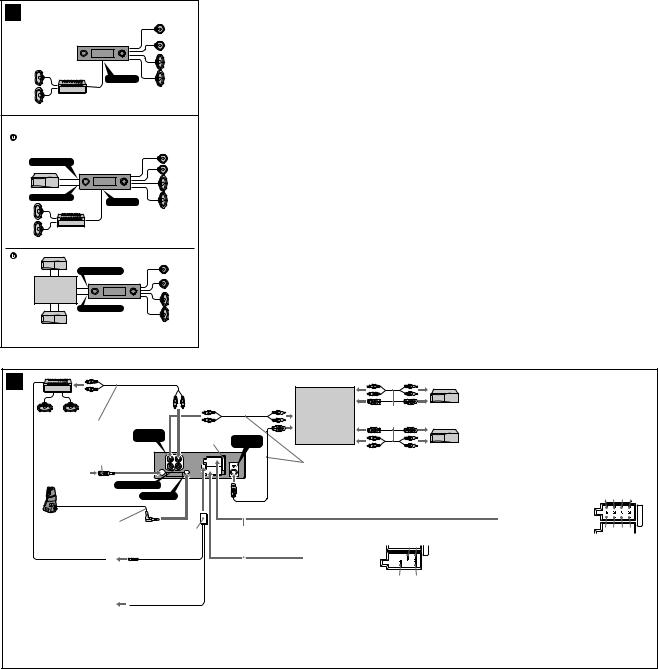
Connection example (2)
Notes (2-A,-B-  )
)
•Be sure to connect the earth cord before connecting the amplifier.
•If you connect an optional power amplifier and do not use the built-in amplifier, the beep sound will be deactivated.
Tip (2-B- )
)
For connecting two or more changers, the source selector XA-C30 (optional) is necessary.
Connection diagram (3)
ATo AMP REMOTE IN of an optional power amplifier
This connection is only for amplifiers. Connecting any other system may damage the unit.
BTo the interface cable of a car telephone
Warning
If you have a power aerial without a relay box, connecting this unit with the power connecting cord (not supplied) may damage the aerial.
Notes on the control leads
•The power aerial control lead (blue) supplies +12 V DC when you turn on the tuner or when you activate the ATA (Automatic Tuner Activation), AF (Alternative Frequency) or the TA (Traffic Announcement) function.
•When your car has built-in FM/MW/LW aerial in the rear/side glass, connect the power aerial control lead (blue) or the accessory power input lead (red) to the power terminal of the existing aerial booster. For details, consult your dealer.
•A power aerial without a relay box cannot be used with this unit.
Memory hold connection
When the yellow power input lead is connected, power will always be supplied to the memory circuit even when the ignition switch is turned off.
Notes on speaker connection
•Before connecting the speakers, turn the unit off.
•Use speakers with an impedance of 4 to 8 ohms, and with adequate power handling capacities to avoid its damage.
•Do not connect the speaker terminals to the car chassis, or connect the terminals of the right speakers with those of the left speaker.
•Do not attempt to connect the speakers in parallel.
•Connect only passive speakers. Connecting active speakers (with built-in amplifiers) to the speaker terminals may damage the unit.
Teileliste (1)
Die Nummern in der Liste sind dieselben wie im Erläuterungstext.
Sicherheitshinweis
Seien Sie beim Umgang mit der Halterung 1 vorsichtig, damit Sie sich nicht die Hände verletzen.
1
Anschlußbeispiel (2)
Hinweise (2-A,-B- )
•Schließen Sie unbedingt zuerst das Massekabel an, bevor Sie den Verstärker anschließen.
•Wenn Sie einen gesondert erhältlichen Endverstärker anschließen und den integrierten Verstärker nicht benutzen, wird der Signalton deaktiviert.
Tip (2-B- )
Zum Anschließen von zwei oder mehr CD/MD-Wechslern wird der gesondert erhältliche Signalquellenwähler XA-C30 benötigt.
Anschlußdiagramm (3)
AAn AMP REMOTE IN des gesondert erhältlichen Endverstärkers
Dieser Anschluß ist ausschließlich für Verstärker gedacht. Schließen Sie nichts anderes daran an. Andernfalls kann das Gerät beschädigt werden.
BAn Schnittstellenkabel eines Autotelefons
Warnung
Wenn Sie eine Motorantenne ohne Relaiskästchen verwenden, kann durch Anschließen dieses Geräts mit dem Stromversorgungskabel (nicht mitgeliefert) die Antenne beschädigt werden.
Hinweise zu den Steuerleitungen
• Die Motorantennen-Steuerleitung (blau) liefert + 12 V Gleichstrom, wenn Sie den Tuner einschalten oder die ATA- (Automatische TunerAktivierung), die AF- (Alternativfrequenzsuche) bzw. die TA-Funktion (Verkehrsdurchsagen) aktivieren.
•Wenn das Fahrzeug mit einer in der Heck-/Seitenfensterscheibe integrierten FM (UKW)/MW/LW-Antenne ausgestattet ist, schließen Sie die Motorantennen-Steuerleitung (blau) oder die Zubehörstromversorgungsleitung (rot) an den Stromversorgungsanschluß des vorhandenen Antennenverstärkers an. Näheres dazu erfahren Sie bei Ihrem Händler.
•Es kann nur eine Motorantenne mit Relaiskästchen angeschlossen werden.
Stromversorgung des Speichers
Wenn das gelbe Stromversorgungskabel angeschlossen ist, wird der Speicher stets (auch bei ausgeschalteter Zündung) mit Strom versorgt.
Hinweise zum Lautsprecheranschluß
•Schalten Sie das Gerät aus, bevor Sie die Lautsprecher anschließen.
•Verwenden Sie Lautsprecher mit einer Impedanz zwischen 4 und 8 Ohm und ausreichender Belastbarkeit. Ansonsten können die Lautsprecher beschädigt werden.
•Verbinden Sie die Lautsprecheranschlüsse nicht mit dem Wagenchassis, und verbinden Sie auch nicht die Anschlüsse des rechten mit denen des linken Lautsprechers.
•Versuchen Sie nicht, Lautsprecher parallel anzuschließen.
•An die Lautsprecheranschlüsse dieses Geräts dürfen nur Passivlautsprecher angeschlossen werden. Schließen Sie keine Aktivlautsprecher (Lautsprecher mit eingebauten Verstärkern) an, da diese sonst beschädigt werden können.
Liste des composants (1)
Les numéros de l’illustration correspondent à ceux des instructions.
Avertissement
Manipulez précautionneusement le support 1 pour éviter de vous blesser aux doigts.
1
Exemple de raccordement (2)
Remarques (2-A,-B- )
•Raccordez d’abord le fil de masse avant de connecter l’amplificateur.
•Si vous raccordez un amplificateur de puissance indépendant et si vous n’utilisez pas l’amplificateur intégré, le bip sera désactivé.
Conseil (2-B- )
Dans le cas du raccordement de deux changeurs de CD/MD ou plus, le sélecteur de source XA-C30 (en option) est indispensable.
Schémas de raccordement (3)
AAu niveau du AMP REMOTE IN d’un amplificateur de puissance en option
Ce raccordement existe seulement pour les amplificateurs. Le raccordement à tout autre système peut endommager l’appareil.
BVers le cordon de liaison d’un téléphone de voiture
Avertissement
Si vous disposez d’une antenne électrique sans relais, le raccordement de cet appareil avec le cordon d’alimentation (non fourni) peut endommager l’antenne.
Remarques sur les fils de contrôle
•La sortie de commande de l’antenne (bleu) fournit du courant continu de +12 V lorsque vous allumez le sélecteur de canaux ou lorsque vous activez la fonction ATA (Activation automatique du syntoniseur), AF (fréquence alternative) ou TA (informations circulation).
•Lorsque votre voiture est équipée d’une antenne FM/MW/LW intégrée dans la vitre arrière/latérale, raccordez la sortie de commande de l’antenne (bleu) ou l’entrée d’alimentation des accessoires (rouge) au bornier de l’amplificateur d’antenne existant. Pour plus de détails, consultez votre revendeur.
•Une antenne électrique sans boitier de relais ne peut pas être utilisée avec cet appareil.
Raccordement pour la sauvegarde de la mémoire
Lorsque le fil d’entrée d’alimentation jaune est raccordé, le circuit de la mémoire est alimenté en permanence même si la clé de contact est sur la position d’arrêt.
Remarques sur le raccordement des haut-parleurs
•Avant de raccorder les haut-parleurs, mettez l’appareil hors tension.
•Utilisez des haut-parleurs ayant une impédance de 4 à 8 ohms avec une capacité de manipulation adéquate pour éviter de les endommager.
•Ne raccordez pas les bornes du système de haut-parleurs au châssis de la voiture et ne raccordez pas les bornes du hautparleur droit à celles du haut-parleur gauche.
•N’essayez pas de raccorder les haut-parleurs en parallèle.
•Raccordez uniquement des haut-parleurs passifs. Le raccordement de haut-parleurs actifs (avec amplificateurs intégrés) aux bornes des haut-parleurs peut endommager l’appareil.
Elenco dei componenti (1)
I numeri nella lista corrispondono a quelli riportati nelle istruzioni.
Attenzione
Maneggiare la staffa 1 con cautela per evitare di ferirsi le mani.
1
Esempi di collegamento (2)
Note (2-A,-B- )
•Assicurarsi di collegare il cavo di terra prima di collegare l’apparecchio all’amplificatore.
•Se si effettua il collegamento di un amplificatore di potenza opzionale e l’amplificatore incorporato non viene utilizzato, il segnale acustico si disattiva.
Suggerimento (2-B- )
Per collegare due o più cambia CD/MD, si deve utilizzare il selettore di fonte XA-C30 (opzionale).
Schema di collegamento (3)
AA AMP REMOTE IN di un amplificatore di potenza opzionale
Questo collegamento è riservato esclusivamente agli amplificatori. Non collegare un tipo di sistema diverso onde evitare di causare danni all’apparecchio.
BAl cavo interfaccia di un telefono per auto
Avvertenza
Quando si collega l’apparecchio con il cavo di alimentazione (non in dotazione), si potrebbe danneggiare l’antenna elettrica se questa non dispone di scatola a relè.
Note sui cavi di controllo
•Il cavo (blu) di controllo dell’antenna elettrica fornisce alimentazione pari a +12 V CC quando si attiva il sintonizzatore o la funzione ATA (attivazione automatica sintonizzatore), AF (frequenza alternativa) o TA (notiziario sul traffico) .
•Se l’automobile è dotata di antenna FM/MW/LW incorporata nel vetro posteriore/laterale, collegare il cavo (blu) di controllo dell’antenna elettrica o il cavo (rosso) di ingresso dell’alimentazione opzionale al terminale di alimentazione del preamplificatore dell’antenna esistente. Per ulteriori informazioni, consultare il proprio fornitore.
•Non è possibile utilizzare un’antenna elettrica senza scatola a relè con questo apparecchio.
Collegamento per la conservazione della memoria
Quando il cavo di ingresso alimentazione giallo è collegato, viene sempre fornita alimentazione al circuito di memoria anche quando la chiavetta di accensione è spenta.
Note sul collegamento dei diffusori
•Prima di collegare i diffusori spegnere l’apparecchio.
•Utilizzare diffusori di impedenza compresa tra 4 e 8 ohm e con capacità di potenza adeguata, altrimenti i diffusori potrebbero venire danneggiati.
•Non collegare i terminali del sistema diffusori al telaio dell’auto e non collegare i terminali del diffusore destro a quelli del diffusore sinistro.
•Non collegare i diffusori in parallelo.
•Non collegare alcun diffusore attivo (con amplificatore incorporato) ai terminali dei diffusori dell’apparecchio perché si potrebbero danneggiare i diffusori attivi. Assicurarsi di collegare diffusori passivi a questi terminali.
Onderdelenlijst (1)
De nummers in de afbeelding verwijzen naar die in de montageaanwijzingen.
Opgelet
Houd de beugel 1 voorzichtig vast zodat u uw vingers niet verwondt.
1
Voorbeeldaansluitingen (2)
Opmerkingen (2-A,-B-  )
)
•Sluit eerst de massakabel aan alvorens de versterker aan te sluiten.
•Wanneer u een los verkrijgbare vermogensversterker aansluit en de ingebouwde versterker niet gebruikt, wordt de pieptoon uitgeschakeld.
Tip (2-B- )
)
Om twee of meer CD/MD-wisselaars aan te sluiten, hebt u de geluidsbronkiezer XA-C30 (optioneel) nodig.
Aansluitschema (3)
ANaar AMP REMOTE IN van een los verkrijgbare vermogensversterker
Deze aansluiting is alleen bedoeld voor versterkers. Door een ander systeem aan te sluiten kan het toestel worden beschadigd.
BNaar het interface-snoer van een autotelefoon
Opgelet
Indien u beschikt over een elektrische antenne zonder relaiskast, kan de antenne worden beschadigd wanneer u dit toestel aansluit met behulp van de voedingskabel (niet meegeleverd).
Opmerking betreffende de aansluitsnoeren
•De antennevoedingskabel (blauw) levert +12 V gelijkstroom als de tuner wordt ingeschakeld of als de functie ATA (Automatische Tuner Activering), AF (Alternatieve Frequenties) of TA (verkeersinformatie) werdt geactiveerd.
•Wanneer uw auto is uitgerust met een FM/MW/LW-antenne in de achterruit/voorruit, moet u de antennevoedingskabel (blauw) of de hulpvoedingskabel (rood) aansluiten op de voedingsingang van de bestaande antenneversterker. Raadpleeg uw dealer voor meer details.
•Met dit apparaat is het niet mogelijk een automatische antenne zonder relaishuis te gebruiken.
Instandhouden van het geheugen
Zolang de gele stroomdraad is aangesloten, blijft de stroomvoorziening van het geheugen intact, ook wanneer het contact van de auto wordt uitgeschakeld.
Opmerkingen betreffende het aansluiten van de luidsprekers
•Zorg dat het apparaat is uitgeschakeld, alvorens de luidsprekers aan te sluiten.
•Gebruik luidsprekers met een impedantie van 4 tot 8 Ohm en let op dat die het vermogen van de versterker kunnen verwerken. Als dit wordt verzuimd, kunnen de luidsprekers ernstig beschadigd raken.
•Verbind in geen geval de aansluitingen van de luidsprekers met het chassis van de auto en sluit de aansluitingen van de rechter en linker luidspreker niet op elkaar aan.
•Probeer nooit de luidsprekers parallel aan te sluiten.
•Sluit geen actieve luidsprekers (met ingebouwde versterkers) aan op de luidspreker-aansluiting van dit apparaat. Dit zal leiden tot beschadiging van het toestel. Sluit dus altijd uitsluitend luidsprekers zonder ingebouwde versterker aan.
6
XR-CA600/CA600V/CA600X
4 A
5 |
1 |
|
|
2 |
|
|
182 |
mm |
|
|
|
|
|
|
|
|
|
53 |
mm |
|
|
|
|
1
Bend these claws outward for a tight fit, if necessary.
Falls erforderlich, diese Klammern für einen sicheren Halt hochbiegen.
Plier ces griffes pour assurer une prise correcte si nécessaire.
Piegare questi morsetti verso l’esterno per un‘installazione più sicura, se necessario.
Indien nodig kunt u deze lipjes ombuigen voor een steviger bevestiging.
Precautions |
Vorsichtsmaßnahmen |
• Choose the installation location carefully so that the |
• Wählen Sie den Einbauort sorgfältig so aus, daß das |
unit will not interfere with normal driving operations. |
Gerät beim Fahren nicht hinderlich ist. |
• Avoid installing the unit in areas subject to dust, dirt, |
• Bauen Sie das Gerät so ein, daß es keinen hohen |
excessive vibration, or high temperature, such as in |
Temperaturen (keinem direkten Sonnenlicht, keiner |
direct sunlight or near heater ducts. |
Warmluft von der Heizung), keinem Staub, keinem |
• Use only the supplied mounting hardware for a safe |
Schmutz und keinen starken Vibrationen ausgesetzt |
and secure installation. |
ist. |
• There must be a distance of at least 15 cm between the |
• Für eine sichere Befestigung verwenden Sie stets nur |
cassettes slot of the unit and shift lever to insert |
die mitgelieferten Montageteile. |
cassette easily. Choose the installation location |
• Zwischen dem Kassettenfach des Geräts und dem |
carefully so the unit does not interfere with gear |
Schalthebel des Fahrzeugs muß ein Abstand von |
shifting and other driving operations. |
mindestens 15 cm sein, damit eine Kassette mühelos |
|
eingelegt werden kann. Wählen Sie den Einbauort |
|
sorgfältig so aus, daß das Gerät beim Schalten nicht |
|
hinderlich ist. |
15 cm
Mounting angle adjustment
Adjust the mounting angle to less than 20°.
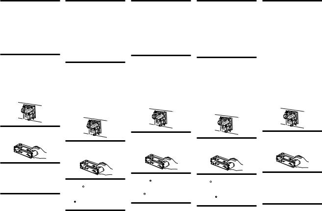
How to detach and attach the front panel (4)
Before installing the unit, detach the front panel.
4-A To detach
Before detaching the front panel, be sure to press (OFF). Press (OPEN), then slide the front panel to the right side, and pull out the left side.
4-B To attach
Place the hole in the front panel onto the spindle on the unit as illustrated, then push the left side in.
Mounting example (5)
Installation in the dashboard
Warning when installing in a car without ACC (accessory) position on the ignition key switch
Be sure to press (OFF) on the unit for two seconds to turn off the clock display after turning off the engine.
When you press (OFF) only momentarily, the clock display does not turn off and this causes battery wear.
RESET button
When the installation and connections are completed, be sure to press the RESET button with a ballpoint pen, etc.
15 cm
Hinweis zum Montagewinkel
Das Gerät sollte in einem Winkel von weniger als 20° montiert werden.
Abnehmen und Anbringen der
Frontplatte (4)
Nehmen Sie die Frontplatte vor dem Einbau des Geräts ab.
4-A Abnehmen
Drücken Sie auf jeden Fall (OFF), bevor Sie die Frontplatte abnehmen. Drücken Sie (OPEN), schieben Sie dann die Frontplatte nach rechts, und ziehen Sie sie an der linken Seite heraus.
4-B Anbringen
Setzen Sie die Aussparung an der Frontplatte wie in der Abbildung dargestellt am Stift am Gerät an, und drücken Sie dann die linke Seite hinein.
Anschlußbeispiel (5)
Installation im Armaturenbrett
Warnhinweis zur Installation des Geräts in einem Auto mit
Zündschloß ohne Zubehörposition
ACC oder I
Drücken Sie am Gerät unbedingt zwei Sekunden lang (OFF), um die Uhrzeitanzeige auszuschalten, nachdem Sie den Motor ausgeschaltet haben.
Wenn Sie (OFF) nur kurz drücken, wird die Uhrzeitanzeige nicht ausgeschaltet, und der Autobatterie wird Strom entzogen.
Taste RESET
Nach der Installation und dem Anschluß muß die Taste RESET mit einem Kugelschreiber o. ä. gedrückt werden.
B
c
3 |
4 |
|
|
|
Dashboard |
Fire wall |
|
|
Armaturenbrett |
Motorraumtrennwand |
|
|
Tableau de bord |
Paroi ignifuge |
|
|
Cruscotto |
Parete tagliafiamma |
|
|
Dashboard |
Brandschot |
|
5 |
1 |
|
|
|
|
||
|
4 |
2 |
|
6 |
6 5 |
||
|
|||
|
6 5 |
|
 3
3
Précautions |
Precauzioni |
Voorzorgsmaatregelen |
• Choisissez soigneusement l’emplacement de |
• Scegliere con attenzione la posizione per |
• Kies de installatieplaats zorgvuldig zodat het toestel |
l’installation afin que l’appareil ne gêne pas la |
l’installazione in modo che l’apparecchio non |
de bestuurder niet hindert tijdens het rijden. |
conduite normale du véhicule. |
interferisca con le operazioni di guida del conducente. |
• Installeer het apparaat niet op plaatsen waar het |
• Evitez d’installer l’appareil dans un endroit exposé à |
• Evitare di installare l’apparecchio dove sia soggetto ad |
blootgesteld wordt aan hoge temperaturen, b.v. in |
la poussière, à la saleté, à des vibrations excessives ou |
alte temperature, come alla luce solare diretta o al |
direct zonlicht of bij de warme luchtstroom van de |
à des températures élevées comme en plein soleil ou à |
getto di aria calda dell’impianto di riscaldamento, o |
autoverwarming, aan sterke trillingen, of waar het in |
proximité de conduits de chauffage. |
dove possa essere soggetto a polvere, sporco e |
contact komt met veel stof of vuil. |
• Pour garantir un montage sûr, n’utilisez que le |
vibrazioni eccessive. |
• Gebruik voor het veilig en stevig monteren van het |
matériel fourni. |
• Usare solo il materiale di montaggio in dotazione per |
apparaat uitsluitend de bijgeleverde montage- |
• Pour pouvoir introduire aisément une cassette, il doit y |
un’installazione stabile e sicura. |
onderdelen. |
avoir une distance d’au moins 15 cm entre le logement |
• Per poter inserire una cassetta facilmente, è necessario |
• De cassettegleuf van het toestel moet minstens 15 cm |
de la cassette de l’appareil et le levier de changement |
che tra la fessura di inserimento della cassetta e la leva |
van de schakelpook af zitten om een cassette |
de vitesses. Choisissez soigneusement l’endroit de |
del cambio vi siano almeno 15 cm di distanza. |
makkelijk te kunnen inbrengen. Kies de |
montage de telle façon que l’appareil ne gêne pas le |
Scegliere la posizione di installazione con attenzione |
installatieplaats zorgvuldig zodat het toestel niet |
maniement du changement de vitesses ou toute autre |
in modo da non ostacolare l’uso del cambio né le altre |
hindert bij het schakelen en andere rijhandelingen. |
opération de conduite. |
operazioni di guida. |
|
15 cm |
15 cm |
15 cm |
|
||
Réglage de l’angle de montage |
|
Maximale montagehoek |
Regolazione dell’angolo di montaggio |
Installeer het apparaat nooit onder een hoek van meer |
|
Ajuster l’inclinaison à un angle inférieur à 20°. |
Regolare l’angolo di montaggio in modo che sia |
dan 20° met het horizontale vlak. |
|
inferiore a 20°. |
|
Retrait et pose de la façade (4)
Avant d’installer l’appareil, retirez la façade.
4-A Pour retirer
Avant de retirer la façade, n’oubliez pas d’appuyer d’abord sur (OFF). Appuyez sur (OPEN), puis faites glisser la façade vers la droite et retirez-la par la gauche.
4-B Pour poser
Fixez la partie de la façade sur la partie de l’appareil, comme indiqué sur l’illustration, puis appuyez sur le côté gauche jusqu’au déclic.
Exemple de montage (5)
Installation dans le tableau de bord
Avertissement en cas d’installation dans une voiture dont le contact ne comporte pas de position ACC (accessoires)
Appuyez sur la touche (OFF) de l’appareil pendant deux secondes pour désactiver l’affichage de l’horloge après avoir coupé le moteur.
Si vous n’appuyez que brièvement sur (OFF), l’affichage de l’horloge ne disparaît pas, ce qui provoque la décharge de la batterie.
Touche RESET
Quand l’installation et les raccordements sont terminés, appuyez sur la touche RESET avec un stylo à bille, etc.
Come rimuovere e reinserire il |
Verwijderen en bevestigen van het |
|
afneembare voorpaneel (4) |
||
pannello anteriore (4) |
|
Verwijder, alvorens met het installeren te beginnen, |
Prima di installare l’apparecchio rimuovere il |
het afneembare voorpaneel. |
|
pannello anteriore. |
4-A Verwijderen |
|
|
||
4-A Per rimuoverlo |
Druk eerst op (OFF) alvorens het voorpaneel los te |
|
Prima di rimuovere il pannello anteriore, assicurarsi di |
maken. Druk op (OPEN), schuif het voorpaneel naar |
|
premere (OFF). Premere (OPEN), quindi far scivolare il |
rechts en trek het los aan de linkerkant. |
|
pannello anteriore verso destra e tirare il lato sinistro |
4-B Bevestigen |
|
verso di sé. |
||
4-B Per reinserirlo |
Breng deel van het voorpaneel aan op deel van |
|
het apparaat zoals afgebeeld en druk op de linkerzijde |
||
Applicare il foro del pannello anteriore al mandrino |
tot deze vastklikt. |
|
dell’apparecchio come mostrato nell’illustrazione e |
|
|
premere il lato sinistro fino a sentire uno scatto. |
|
|
Esempi di collegamento (5)
Installazione nel cruscotto
Informazioni importanti per quando si effettua l’installazione su un’auto sprovvista della posizione ACC sull’interruttore di accensione
Assicurarsi di premere (OFF) sull’apparecchio per due secondi per spegnere il display dell’orologio dopo che il motore è stato spento.
Se si preme (OFF) solo per un attimo, il display dell’orologio non si spegne causando in questo modo lo scaricamento della batteria.
Tasto RESET
Dopo avere terminato l’installazione e i collegamenti, assicurarsi di premere il tasto RESET con la punta di una penna a sfera o di un altro oggetto appuntito.
Voorbeeldaansluitingen (5)
Montage in het dashboard
Opgelet bij het monteren in een auto waarvan het contactslot geen ACC (accessory) stand heeft
Druk (OFF) op het toestel gedurende twee seconden in om de klokweergave uit te schakelen na het afzetten van de motor.
Indien u slechts even op (OFF) drukt, verdwijnt de tijdindicatie niet waardoor de batterij uitgeput raakt.
RESET-toets
Druk, nadat u het apparaat heeft geïnstalleerd en de aansluitingen heeft gemaakt, met een balpen of een ander puntig voorwerp op de RESET-toets.
7
XR-CA600/CA600V/CA600X
SECTION 2
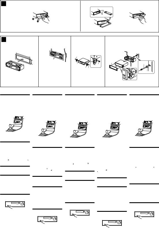
DISASSEMBLY
• This set can be disassembled in the order shown below.
2-1. DISASSEMBLY FLOW
Note 1: The process described in 

 can be performed in any order.
Note 2: Without completing the process described in 

 , the next process can not be performed.
Note 3: Illustration of disassembly is omitted.
SET
|
|
|
|
|
|
FRONT PANEL SECTION |
|
COVER |
|
|
(Note 3) |
|
(Note 3) |
|
|
|
|
|
|
|
|
|
|
|
2-2. MECHANISM DECK (MG-25G-136) (Page 8)
2-3. MAIN BOARD
(Page 9)
2-4. HEAT SINK (ISO2P) (Page 9)
Note: Follow the disassembly procedure in the numerical order given.
2-2. MECHANISM DECK (MG-25G-136)
7 screw (PTT2.6 × 6)
8 mechanism deck (MG-25G-136)
6 connector (CN351)
 5 flexible board (CN301)
2 two claws
4 sub panel assy
1 screw (PTT2.6 × 6)
1 two screws |
3 flat flexible (14core) cable |
||
(CN701) |
|
||
(PTT2.6 × |
6) |
|
|
|
|
||
|
|
1 screw (PTT2.6 × |
2 claw |
|
|
6) |
|
8
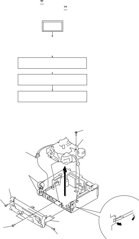
2-3. MAIN BOARD
3 rubber cap (25)
2 three ground point screws (PTT2.6 × 6) 
4 main board
2-4. HEAT SINK (ISO2P)
3 heat sink (ISO2P)
XR-CA600/CA600V/CA600X
1 three screws (PTT2.6 × 8)
1three screws (PTT2.6 × 8)
2 two screws (PTT2.6 × 12)
1 two screws (PTT2.6 × 8)
9

XR-CA600/CA600V/CA600X
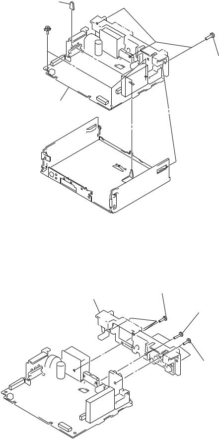
SECTION 3
ASSEMBLY OF MECHANISM DECK
Note: Follow the assembly procedure in the numerical order given.
3-1. HOUSING
5 Fit projection on C part.
2Install the hanger onto two claws of the housing.
4 Fit claw on B part.
3Put the housing under A part.
housing
C part
7 Hold the hanger by bending the claw.
1 Install the catch to the hanger.
hanger
6 Fit projection on D part.
8Hold the hanger by bending the claw.
D part
A part
B part
3-2. ARM (SUCTION)
2 Move the arm (suction) in the arrow direction and fit on projection.
projection
1 Fit the arm (suction) on the shaft.
10
XR-CA600/CA600V/CA600X
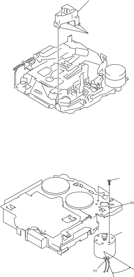
3-3. LEVER (LDG-A) / (LDG-B)
shaft A |
shaft A |
|
|
shaft B |
|
shaft C |
shaft B |
|
1Fit the lever (LDG-A) on shafts A – C and install it.
3 type-E stop ring 2.0
2Fit the lever (LDG-B) on shafts A and B and install it.
3-4. GEAR (LDG-FT)
gear (LDG-D)
6 polyethylene washer
hole
5 gear (LDG-FT)
hole |
lever (LDG-A) |
gear (LDG-FB)
4Align hole in the gear (LDG-D) with hole the lever (LDG-A).
1
2 tension spring (LD-2)
2 tension spring (LD-1)
3Move the lever (LDG-B) in the arrow direction.
11
XR-CA600/CA600V/CA600X
3-5. GUIDE (C)
2 guide (C)
1 three claws
3-6. MOUNTING POSITION OF CAPSTAN/REEL MOTOR (M901)
Note: Mount the motor so that the angle between  of the motor and the hole for the screw
  becomes 30° as shown in this figure.
two precision screws (P2 × 2)
capstan/reel motor (M901)
30˚
12
Loading...