


MULTI CHANNEL AV RECEIVER
Operating Instructions |
US |
|
|
|
|
|
|
Mode d’emploi |
FR |
|
|
|
|
|
|
Manual de instrucciones |
ES |
|
|
|
|
STR-ZA3100ES/STR-ZA2100ES/STR-ZA1100ES
Owner’s Record
The model and serial numbers are located on the rear panel of the unit. Record these numbers in the spaces provided below. Refer to these numbers whenever you call upon your Sony dealer regarding this product.
Model No.
Serial No.
WARNING
To reduce the risk of fire or electric shock, do not expose this apparatus to rain or moisture.
To reduce the risk of fire, do not cover the ventilation opening of the appliance with newspapers, tablecloths, curtains, etc.
Do not expose the appliance to naked flame sources (for example, lighted candles).
To reduce the risk of fire or electric shock, do not expose this appliance to dripping or splashing, and do not place objects filled with liquids, such as vases, on the appliance.
As the main plug is used to disconnect the unit from the mains, connect the unit to an easily accessible AC outlet. Should you notice an abnormality in the unit, disconnect the main plug from the AC outlet immediately.
Do not expose batteries or appliances with battery-installed to excessive heat, such as sunshine and fire.
The unit is not disconnected from the mains as long as it is connected to the AC outlet, even if the unit itself has been turned off.
For the customers in the U.S.A.
This symbol is intended to alert the user to the presence of the Hot Surface that may be hot if it is touched during the normal operation.
This symbol is intended to alert the user to the presence of uninsulated “dangerous voltage” within the product’s enclosure that may be of sufficient magnitude to constitute a risk of electric shock to persons.
This symbol is intended to alert the user to the presence of important operating and maintenance (servicing) instructions in the literature accompanying the appliance.
Important Safety Instructions
1)Read these instructions.
2)Keep these instructions.
3)Heed all warnings.
4)Follow all instructions.
5)Do not use this apparatus near water.
6)Clean only with dry cloth.
7)Do not block any ventilation openings. Install in accordance with the manufacturer’s instructions.
8)Do not install near any heat sources such as radiators, heat registers, stoves, or other apparatus (including amplifiers) that produce heat.
9)Do not defeat the safety purpose of the polarized or grounding-type plug. A polarized plug has two blades with one wider than the other. A grounding type plug has two blades and a third grounding prong. The wide blade or the third prong are provided for your safety. If the provided plug does not fit into your outlet, consult an electrician for replacement of the obsolete outlet.
10)Protect the power cord from being walked on or pinched particularly at plugs, convenience receptacles, and the point where they exit from the apparatus.
11)Only use attachments/accessories specified by the manufacturer.
12)Use only with the cart, stand, tripod, bracket, or table specified by the manufacturer, or sold with the apparatus. When a cart is used, use caution when moving the cart/apparatus combination to avoid injury from tipover.
2US

13)Unplug this apparatus during lightning storms or when unused for long periods of time.
14)Refer all servicing to qualified service personnel. Servicing is required when the apparatus has been damaged in any way, such as power-supply cord or plug is damaged, liquid has been spilled or objects have fallen into the apparatus, the apparatus has been exposed to rain or moisture, does not operate normally, or has been dropped.
To reduce the risk of electric shock, the speaker cord should be connected to the apparatus and the speakers in accordance with the following instructions.
1)Disconnect the AC power cord from the MAINS.
2)Strip 10 to 15 mm of the wire insulation of the speaker cord.
3)Connect the speaker cord to the apparatus and the speakers carefully so as not to touch the core of speaker cord by hand. Also disconnect the AC power cord from the MAINS before disconnecting the speaker cord from the apparatus and the speakers.
NOTE:
This equipment has been tested and found to comply with the limits for a Class B digital device, pursuant to Part 15 of the FCC Rules. These limits are designed to provide reasonable protection against harmful interference in a residential installation. This equipment generates, uses and can radiate radio frequency energy and, if not installed and used in accordance with the instructions, may cause harmful interference to radio communications.
However, there is no guarantee that interference will not occur in a particular installation. If this equipment does cause harmful interference to radio or television reception, which can be determined by turning the equipment off and on, the user is encouraged to try to correct the interference by one or more of the following measures:
Reorient or relocate the receiving antenna.
Increase the separation between the equipment and receiver.
Connect the equipment into an outlet on a circuit different from that to which the receiver is connected.
Consult the dealer or an experienced radio/TV technician for help.
CAUTION
You are cautioned that any changes or modifications not expressly approved in this manual could void your authority to operate this equipment.
Properly shielded and grounded cables and connectors must be used for connection to host computers and/or peripherals in order to meet FCC emission limits.
For the customers in Canada
Properly shielded and grounded cables and connectors must be used for connection to host computers and/or peripherals.
Copyrights
This receiver incorporates Dolby* Digital Surround and the DTS** Digital Surround System.
*Manufactured under license from Dolby Laboratories. Dolby, Dolby Atmos, Dolby Surround, and the double-D symbol are trademarks of
Dolby Laboratories.
**For DTS patents, see
http://patents.dts.com. Manufactured under license from DTS, Inc. DTS, the Symbol, DTS in combination with the Symbol, DTS:X, and the DTS:X logo are registered trademarks or trademarks of DTS, Inc. in the United States and/or other countries. © DTS, Inc. All Rights Reserved.
This receiver incorporates High-Definition Multimedia Interface (HDMI™) technology.
The terms HDMI and HDMI High-Definition Multimedia Interface, and the HDMI Logo are trademarks or registered trademarks of HDMI Licensing, LLC in the United States and other countries.
3US

Precautions
On safety
Should any solid object or liquid fall into the cabinet, unplug the receiver and have it checked by qualified personnel before operating it any further.
On power sources
Before operating the receiver, check that the operating voltage is identical with your local power supply.
The operating voltage is indicated on the nameplate on the back of the receiver.
If you are not going to use the receiver for a long time, be sure to disconnect the receiver from the wall outlet. To disconnect the AC power cord (mains lead), grasp the plug itself; never pull the cord.
One blade of the plug is wider than the other for the purpose of safety and will fit into the wall outlet only one way. If you are unable to insert the plug fully into the outlet, contact your dealer.
AC power cord (mains lead) must be changed only at a qualified service shop.
On heat buildup
Although the receiver heats up during operation, this is not a malfunction. If you continuously use this receiver at a large volume, the cabinet temperature of the top, side and bottom rises considerably*. To avoid burning yourself, do not touch the cabinet.
*The top of the cabinet may become too hot to touch.
On placement
Do not install the appliance in a confined space, such as a bookcase.
Sufficient space around the receiver is needed to release heat. When placing the receiver in a rack, leave more than 44.45 mm (1.75 in) space above the receiver, and more than 44.45 mm (1.75 in) space along the sides of the receiver. The rack behind the receiver should be open. If you place the receiver with its back against the wall, leave more than
88.9 mm (3.5 in) space between the receiver and the wall.
Make sure to use a “WS-RE1” dedicated rack mount kit for this receiver when mounting the receiver on a rack mount.
Place the receiver in a location with adequate ventilation to prevent heat buildup and prolong the life of the receiver.
Do not place the receiver near heat sources, or in a place subject to direct sunlight, excessive dust, or mechanical shock.
Do not place anything on top of the cabinet that might block the ventilation holes and cause malfunctions.
Magnets are attached to both the front panel and front cover. Do not place cards with magnetic stripes, such as bank cards or ID passes, near the receiver. These cards may become unusable due to the effects of the magnets on the receiver.
On cleaning
Clean the cabinet, panel, and controls with soft dry cloth. Do not use any type of abrasive pad, scouring powder, or solvent, such as alcohol or benzine.
If you have any questions or problems concerning your receiver, please consult your nearest Sony dealer.
4US

Main features of the receiver
Refer to the Help Guide for details of each function.
http://rd1.sony.net/help/ha/strza312111/h_uc2/
Compatible with a variety of connections and formats
Feature |
Description |
Compatible with The receiver allows you to enjoy sounds of Dolby Dolby Atmos and Atmos or DTS:X content with realistic sensation that
DTS:X will make you feel like you are there. The receiver can decode up to 9 channels using the extra power
amplifier (for STR-ZA3100ES/STR-ZA2100ES) or up to 7 channels (for STR-ZA1100ES).
Furthermore, the receiver is compatible with various audio formats, such as Dolby TrueHD, DTS-HD Master Audio, DSD, and multi-channel Linear PCM.
HDMI (6 input (1 in front), 2 output) (for STR-ZA3100ES/ STR-ZA2100ES)
HDMI (5 input, 2 output) (for STRZA1100ES)
You can connect a variety of equipment to the many available HDMI input jacks.
One HDMI output jack supports the multi-zone feature, which allows you to output content other than that of the main room.
The receiver is compatible with various HDMI standards, such as Deep Color, 4K and 3D transmission, and Audio Return Channel (ARC).
4K
All HDMI jacks can input or output 4K signals. All HDMI jacks support High-bandwidth Digital Content Protection System Revision 2.2 (HDCP 2.2). Refer to “Specifications” (page 20) for details.
You can convert analog audio input signals and tuner audio signals to digital signals and then output them from the HDMI OUT B (ZONE 2) jack.
Switching hub (for The receiver is equipped with a switching hub
STR-ZA3100ES only) (8 ports) that supports gigabit-speed transfer. Two of the ports support PoE (Power over Ethernet).
Feature |
Description |
Multi-zone |
You can enjoy in another room music and video |
|
content different from the content being played in |
|
the main room. |
|
|
|
You can enjoy all audio input on a TV or other device |
|
connected in zone 2. |
|
Digital audio signals input from HDMI IN, OPTICAL IN |
|
or COAXIAL IN jack can be output to zone 2 speakers, |
|
the ZONE 2 AUDIO OUT jack and the HDMI OUT B |
|
(ZONE 2) jack. |
Supports playback of You can enjoy playing back video and audio signals
various signal |
in a variety of formats. |
|
formats |
For details on which signals the receiver supports, |
|
refer to “Supported video formats” (page 22) and |
||
|
||
|
“Supported digital audio formats” (page 22) under |
|
|
“Specifications.” |
|
|
|
Better image and sound quality
Feature Description
ES (Award-winning The receiver achieves superior surround playback
Premium products) with discrete 7-channel high-power amplifiers and build & sound quality high-quality hardware.
Full-performance |
Fast moving content can be played back at a higher |
playback of 4K |
quality because all HDMI jacks on the receiver |
premium content* |
support HDCP 2.2 and HDR. |
*We recommend using a Premium High Speed HDMI Cable with Ethernet, which can support bandwidths of up to 18 Gbps. To use high-bandwidth video formats such as 4K/60p 4:4:4, you need to change the HDMI signal format settings on the receiver and the connected device. For details on high-bandwidth video formats and other notes, refer to the Help Guide.
In-Ceiling Speaker |
The receiver has a speaker mode to match sound |
Mode |
with the screen position even when you use speakers |
|
set up at ceiling level. |
Sound Optimizer |
The Sound Optimizer function optimizes audio |
|
output in accordance with the volume level. |
|
|
Sound fields |
You can select from a variety of sound field modes |
|
according to speaker connections or input sources. |
|
(2ch Stereo, Direct, A.F.D., etc.) |
|
|
continued
5US

Feature |
Description |
Speaker Relocation The receiver analyses the distance and the angle to
with A.P.M. (D.C.A.C. the speakers by using the supplied stereo calibration
EX) function microphone. With these information and Speaker Relocation with A.P.M. (D.C.A.C. EX) function, the
receiver’s DSP produces optimum sound by simulating ideally positioned and angled speakers.
Center Speaker Lift By using the front high speakers, you can lift up the Up sounds of the center speaker to an appropriate
height on the screen, allowing you to enjoy natural sound without discomfort. For details, refer to the Help Guide.
Bi-amplifier connection
You can enhance the sound quality of the front speakers by connecting different amplifiers to the tweeter and woofer using a bi-amplifier connection. For details on bi-amplifier connections, refer to the Help Guide.
Useful functions
Feature |
Description |
Easy and accessible |
The receiver can display 16 digits on 2 lines, allowing |
operations |
you to make settings without a monitor. |
|
|
|
The CUSTOM PRESET button allows you to call up |
|
various settings all at once. |
|
|
Flexible functions |
The Standby Through function outputs HDMI signals |
|
to the TV, even when the receiver is in standby mode. |
|
|
|
The function allows you to play back video and audio |
|
mixed from different inputs. |
|
|
6US

Table of contents |
|
Manuals provided for this product..................................... |
8 |
Main parts and controls ..................................................... |
9 |
Preparation 1: Preparing the receiver and the remote |
|
control.......................................................................... |
13 |
Preparation 2: Performing Easy Setup .............................. |
14 |
Enjoying video/sound from the connected device........... |
15 |
Using the menu on the TV screen ..................................... |
16 |
Changing the settings ....................................................... |
17 |
Troubleshooting................................................................ |
18 |
Specifications ................................................................... |
20 |
7US
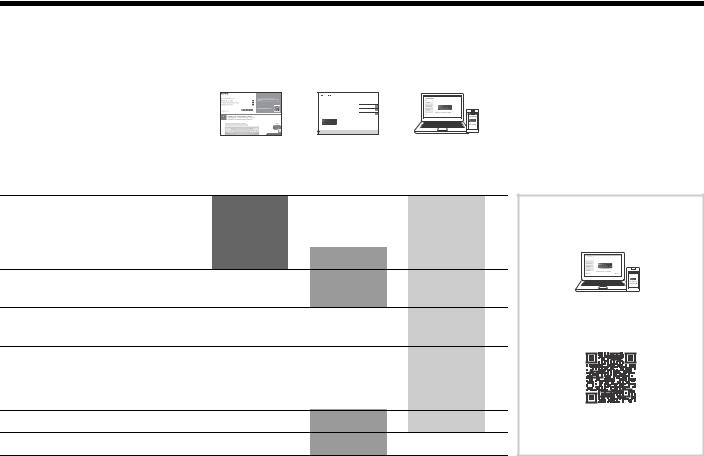
Manuals provided for this product
The following manuals are provided for this product.
The information included in each manual is as shown below:
MULTI CHANNEL
AV RECEIVER
Startup Guide |
Operating |
Help Guide |
|
Instructions |
(online) |
|
(this booklet) |
|
Preparation
Installation
Connections
Initial Setup
Basic operations
Listening/Watching
Advanced operations
Listening/Watching
Advanced operations
Multi-zone features
Other features
Adjusting Settings
Troubleshooting
Precautions/Specifications
To read the Help Guide, go to the following website:
http://rd1.sony.net/help/ha/ strza312111/h_uc2/
8US
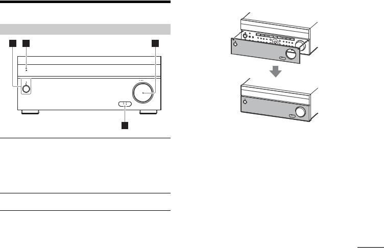
Attaching the front cover
Main parts and controls
Front panel cover
Parts |
Functions |
(power) |
Turns the receiver on or sets it to standby |
|
mode. |
|
The indicator lights up according to the status |
|
of the receiver. Also, the color of the indicator |
|
changes depending on the status of the |
|
receiver. |
|
|
Remote sensor |
Receives signals from the remote control. |
|
|
MASTER VOLUME |
Turns to adjust the volume level. |
HDMI jack cover (for STR-ZA3100ES/ STR-ZA2100ES only)
Open the cover when you use the HDMI IN 6 (GAME) jack.
continued
9US

Front panel
Parts |
Functions |
|
PING |
Displays the IP address and MAC address on |
|
|
the display panel. |
|
|
|
|
Input buttons |
Selects the device you want to play. |
|
|
|
|
TONE MODE, TONE+/– |
Press to adjust the bass/treble level of the |
|
|
speaker. |
|
|
|
|
SPEAKERS |
Switches the front speakers to OFF, A, B or |
|
|
A+B. |
|
|
|
|
CALIBRATION MIC jack |
Connect the supplied calibration microphone |
|
|
for “Auto Calibration” to this jack. |
|
|
|
|
HDMI OUT |
Switches the output for two monitors |
|
|
connected to the HDMI OUT A and HDMI OUT |
|
|
B jacks. |
|
|
|
|
SETTING ( (USB) port) |
Used for maintenance and service. |
|
|
|
|
ZONE CONTROL (ZONE2, |
Selects the location to be controlled. |
|
ZONE3) |
|
|
|
|
|
Tuner control buttons |
Used for tuner operations. |
|
|
|
|
CUSTOM PRESET (1, 2, 3, |
Saves and recalls various settings for the |
|
4) |
receiver. |
|
|
|
|
Menu operation buttons |
Used for menu operations displayed on the |
|
|
TV screen and the display panel of the |
|
|
receiver. |
|
|
HOME: |
Displays the home menu on the |
|
|
TV screen. |
|
AMP MENU: Displays the menu on the |
|
|
|
display panel of the receiver to |
|
|
operate the receiver. |
|
|
|
IN-CEILING SP |
Activates the In-Ceiling Speaker Mode. |
|
|
|
|
SOUND FIELD (2CH/ |
Selects the sound field you want. |
|
DIRECT, A.F.D., MOVIE, |
|
|
MULTI ST.) |
|
|
|
|
|
HDMI IN 6 (GAME) jack |
Connect to a video game console. The video |
|
(for STR-ZA3100ES/ |
and sound from your video game console is |
|
STR-ZA2100ES only) |
input. |
|
|
|
|
10US
Remote Control
Parts |
Functions |
|
MAIN (power) |
Turns the receiver on or sets it to standby |
|
|
mode. |
|
|
|
|
ZONE2, ZONE3, MAIN |
Selects the location to be controlled. |
|
|
|
|
PURE DIRECT |
Press to use the Pure Direct function. |
|
|
|
|
IN-CEILING SP |
Activates the In-Ceiling Speaker Mode. |
|
|
|
|
Menu operation buttons |
Used for menu operations displayed on the |
|
|
TV screen and the display panel of the |
|
|
receiver. |
|
|
HOME: |
Displays the home menu on the |
|
|
TV screen. |
|
AMP MENU: Displays the menu on the |
|
|
|
display panel of the receiver to |
|
|
operate the receiver. |
|
OPTIONS: |
Displays the option menus on |
|
|
the TV screen for item selection. |
|
DISPLAY: |
Displays information on the TV |
|
|
screen. |
|
RETURN: |
Returns to the previous menu. |
|
|
|
INPUT SETUP |
Displays the Input Setup menu. |
|
|
|
|
AUTO CAL |
Press to perform Auto Calibration. |
|
|
|
|
Tuner control buttons |
Used for tuner operations. |
|
|
|
|
INPUT +/– |
Press + or – to select the input source. |
|
|
|
|
INPUT MODE |
Press to select the input mode. |
|
|
|
|
ZONE2 , ZONE3 |
Turns the receiver in zone 2 or zone 3 on or |
|
|
sets it to standby mode. |
|
|
|
|
HDMI OUTPUT |
Switches the output for two monitors |
|
|
connected to the HDMI OUT A and HDMI OUT |
|
|
B jacks. |
|
|
|
|
Input buttons |
Select the device you want to play. |
|
|
When you press any of the input buttons, the |
|
|
receiver turns on. |
|
|
|
|
SOUND OPTIMIZER |
Press to use the Sound Optimizer to enjoy |
|
|
clear and dynamic sound at low volume |
|
|
levels. |
|
|
|
|
CUSTOM PRESET (1, 2, 3, |
Saves and recalls various settings for the |
|
4) |
receiver. |
|
|
|
|
SP SETUP |
Displays the Speaker Setup menu. |
|
|
|
|
TEST (PICTURE, TONE) |
Press to output the test picture or test tone. |
|
|
|
|
continued
11US

Parts |
Functions |
SOUND FIELD (2CH/ |
Selects the sound field you want. |
DIRECT, A.F.D., MOVIE, |
|
MULTI ST.) |
|
|
|
+ (*)/–, |
Adjusts the volume level. |
|
|
*The + button has a tactile dot. Use the tactile dot as a reference when operating the receiver.
12US

Preparation 1: Preparing the receiver and the remote control
Before starting the following steps, connect speakers and AV devices to the receiver referring to the supplied Startup Guide.
1Insert batteries into the remote control with correct polarity.
R03 (size AAA) batteries
2Connect the supplied AC power cord (mains lead) to the AC IN terminal on the receiver firmly, then connect the AC power cord (mains lead) to a wall outlet.
AC power cord (mains lead) (supplied)
* 
 AC IN terminal
 To the wall outlet
*Space remains between the plug and the rear panel even when the power cord (mains lead) is inserted firmly. The cord is supposed be connected this way. This is not malfunction.
3 Press to turn the AV receiver on.
4Place the calibration microphone at your listening position and set it at the same height as your ears.
The calibration microphone is used for setting the speakers (Auto Calibration) in Preparation 2 (Easy Setup).
Perform this step after removing the front cover.
Note
Fully insert the plug of the calibration microphone into the CALIBRATION MIC jack.
5Turn the TV on, and then switch the input of the TV to which the receiver is connected.
13US
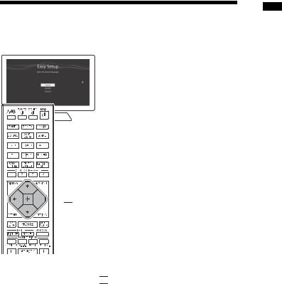
Preparation 2: Performing Easy Setup
The Easy Setup screen appears on the TV screen when you turn on the receiver for the first time or after the receiver is initialized.


 , / / /
1Press / to select the language for the messages on the screen, and then press 

 .
.
2Set up the receiver in accordance with the instructions on the Easy Setup screen.
Notes
If the Easy Setup screen does not appear or you want to display the Easy Setup screen manually, you can display it by selecting [Setup] - [Easy Setup] from the home menu.
The speakers emit very loud sound during the calibration and the volume cannot be adjusted. Be considerate of your neighbors and any children who are present.
14US

|
1 |
|
|
||
Enjoying video/sound from the connected |
||
2 |
||
device |
3 |
4
Turn on the device you want to play.
Turn the receiver on.
Turn the TV on, and then switch the input of the TV to which the receiver is connected.
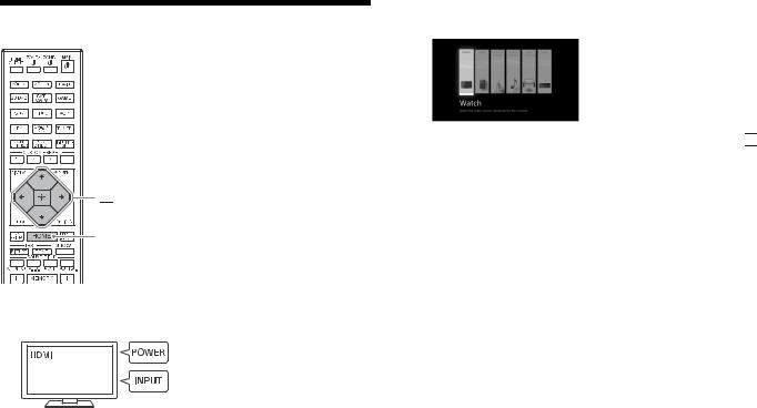
Press HOME.
The home menu is displayed on the TV screen.
|
|
|
|
|
|
|
|
|
|
|
|
|
|
|
|
|
|
, / / / |
|
|
|
|
|
|
|
|
|
|
|
|
|
|
|
|
|
|
|
|
|
|
|
|
|
|
|
|
|
|
|
|
|
|
|
|
|
|
|
|
|
HOME |
|
|
|
|
|
|
|
|
|
|
|
|
|
|
|
|
|
|
|
|
|
|
|
|
|
|
|
|
|
|
|
|
|
|
|
|
|
|
|
|
|
SOUND FIELD |
5 |
Press / repeatedly to select [Watch] or [Listen], and then |
|
|
|
|
|
|
|
|
|
|
|
|
|
|
|
|
|
|
|||
|
|
|
|
|
|
|
|
|
|
|
|
|
|
|
|
|
|
|||
|
|
|
|
|
|
|
|
|
|
|
|
|
|
|
|
|
|
|||
|
|
|
|
|
|
|
|
|
|
|
|
|
|
|
|
|
|
(2CH/DIRECT, |
||
|
|
|
|
|
|
|
|
|
|
|
|
|
|
|
|
|
|
A.F.D., MOVIE, |
|
press . |
|
|
|
|
|
|
|
|
|
|
|
|
|
|
|
|
|
|
MULTI ST.) |
|
|
|
|
|
|
|
|
|
|
|
|
|
|
|
|
|
|
|
|
|
The menu item list appears on the TV screen. |
|
|
|
|
|
|
|
|
|
|
|
|
|
|
|
|
|
|
|
|
6 |
|
|
|
|
|
|
|
|
|
|
|
|
|
|
|
|
|
|
|
|
Select the device you want to play and start playback. |
|
|
|
|
|
|
|
|
|
|
|
|
|
|
|
|
|
|
|
|
||
|
|
|
|
|
|
|
|
|
|
|
|
|
|
|
|
|
|
|
||
|
|
|
|
|
|
|
|
|
|
|
|
|
|
|
|
|
|
+/– |
7 |
Press +/– to adjust the volume. |
|
|
|
|
|
|
|
|
|
|
|
|
|
|
|
|
|
|
|
8 |
You can also use MASTER VOLUME on the receiver. |
|
|
|
|
|
|
|
|
|
|
|
|
|
|
|
|
|
|
|
Press 2CH/DIRECT, A.F.D., MOVIE or MULTI ST. to enjoy the |
|
|
|
|
|
|
|
|
|
|
|
|
|
|
|
|
|
|
|
|
|
surround sound. |
You can also use 2CH/DIRECT, A.F.D., MOVIE or MULTI ST. on the receiver.
15US

Using the menu on the TV screen
You can display the menu of the receiver on the TV screen.


 , / / /
OPTIONS
RETURN |


 HOME
HOME
1Turn the TV on, and then switch the input of the TV to which the receiver is connected.
2Press HOME.
The home menu is displayed on the TV screen.
3Press / repeatedly to select the menu you want to use, and then press 
 to enter the menu.
Home menu items
Watch:
Select to display video from the connected device.
Listen:
Select to listen to sound from the connected device.
Custom Preset:
Select to save various settings for the receiver and recall those settings.
Sound Effects:
Select to enjoy sound effects.
Zone Controls:
Select to adjust settings for Zone 2 or Zone 3.
Setup:
Select to adjust the various settings for the receiver.
Hints
When [OPTIONS] appears in the lower right portion of the TV screen, you can display the function list by pressing OPTIONS and selecting a related function.
To return to the previous screen, press RETURN.
To exit the menu, press HOME to display the home menu, and then press HOME again.
16US
Changing the settings

 , / / /
HOME
1Turn the TV on, and then switch the input of the TV to which the receiver is connected.
2Press HOME.
The home menu is displayed on the TV screen.
3 Press / repeatedly to select [Setup], and then press 

 .
.
4 Select the settings you want to configure.
Example:
To select a sound field
You can select from a variety of sound field modes according to speaker connections or input sources. Select [Setup] - [Audio Setup] - [Sound Field].
2ch Stereo
Direct
A.F.D.
Dolby Surround
Neural:X
Multi Stereo
For Details on each mode, visit the Help Guide.
http://rd1.sony.net/help/ha/strza312111/h_uc2/
17US

Troubleshooting
The following troubleshooting page covers frequently asked questions.
Visit the Help Guide for detailed examples. http://rd1.sony.net/help/ha/strza312111/h_uc2/
You can search by a keyword using the online troubleshooting guide. If you still cannot find a solution, consult your nearest Sony dealer.
General
The top of the receiver is hot.
Phenomenon is specific to this amplifier. This is not a malfunction. If “Control for HDMI” or “Network Standby” is set to “On,” or “Standby Through” is set to “On” or “Auto,” the power for zone 2 is turned on, the top of the receiver may become hot even while the receiver is in standby mode. This condition occurs because current is flowing in the internal circuits of the receiver, and this is normal.
Video
There is no picture or an unclear picture appears on the TV screen or monitor, regardless of type of picture.
Select the appropriate input on the receiver (pages 10, 11).
Set your TV to the appropriate input mode.
Make sure that cables are correctly and securely connected to equipment.
Depending on the playback equipment, equipment may need to be set up. Refer to the operating instructions supplied with the equipment.
Set “HDMI Signal Format” of the selected HDMI IN jack except HDMI IN 6 (GAME) jack (for STR-ZA3100ES/STR-ZA2100ES only) to “Standard format” in the “HDMI Setup” menu.
Specific type of image is not output or corrupted.
HDMI output
The output of the HDMI video signals of the receiver may be set to “OFF.” In this case, select “HDMI OUT A” or “HDMI OUT B” using the HDMI OUT button on the receiver (page 10) or HDMI OUTPUT button on the remote control (page 11).
Sony recommends that you use an HDMI authorized cable or HDMI cable made by Sony. Be sure to use High Speed HDMI™ cables with Ethernet. Premium High Speed HDMI™ cable with Ethernet is required for 4K/60p 4:4:4 8 bit and 4K/60p 4:2:0 10 bit, etc.
4K image
Depending on the TV or video equipment, 4K images may not be displayed. Check the video capability and setting of your TV or video device. Also, make sure to connect to the receiver to an HDMI input jack of a TV or video equipment supporting 4K. You have to connect an HDMI cable to an HDMI jack that supports HDCP 2.2 when you use a playback device for 4K resolution video content, etc.
Audio
There is no sound, no matter which equipment is selected, or only a very low-level sound is heard.
Check that the speakers and equipment are connected correctly.
Check that both the receiver and all equipment are turned on.
Check that MASTER VOLUME control is not set at –∞ dB. Try to set it at about –40 dB.
Check that SPEAKERS is not set to “OFF” (page 10).
Try pressing the input button on the remote control to select the equipment of your choice.
HDMI input
Depending on the playback equipment, equipment may need to be set up. Refer to the operating instructions supplied with the equipment.
18US

Error messages
You can check the status of the receiver by the message. See the following to solve the problem. If any problem persists, consult your nearest Sony dealer.
PROTECTOR
The receiver is covered and ventilation holes are blocked. The receiver will automatically turn off after a few seconds. Remove the object covering the upper panel of the receiver and turn on the power again.
Irregular current is output to the speakers due to a short circuit on the speaker terminals. The receiver will automatically turn off after a few seconds. If the protective device on the receiver is activated due to a short-circuit problem, turn off the receiver.
Check the connection of the speakers and turn on the power again.
UPDATE FAILED
Insert a USB flash drive on which the package file for updating the receiver is saved, and then turn the receiver off and turn it on again.
List of messages after Auto Calibration measurements
Display |
Explanation |
Code 31 |
Front speakers are not selected properly. Select the front |
|
speakers using SPEAKERS and perform the Auto Calibration |
|
again (page 10). |
|
|
Display Explanation
Code 32, Code Speakers were not detected or not connected properly.
33None of the front speakers are connected or only one front speaker is connected.
Either the surround left or surround right speaker is not connected.
A surround back speaker is connected only to the SPEAKERS SURROUND BACK/HEIGHT (FRONT B/BI-AMP/ZONE 2) R terminal. If connecting only one surround back speaker, connect it to the SPEAKERS SURROUND BACK/HEIGHT (FRONT B/BI-AMP/ZONE 2) L terminal.
Either the Height1 left or Height1 right speaker is not connected (for STR-ZA3100ES/STR-ZA2100ES).
Either the Height2 left or Height2 right speaker is not connected (for STR-ZA3100ES/STR-ZA2100ES).
Either the Height left or Height right speaker is not connected (for STR-ZA1100ES).
The calibration microphone is not connected. Make sure that the calibration microphone is connected properly and perform the Auto Calibration again.
If the calibration microphone is connected properly but the error code still appears, the calibration microphone cable may be damaged.
Code 34 |
Speakers are not placed in the proper position. Speakers or a |
|
calibration microphone on the right or left may be placed |
|
wrongly. See the supplied Startup Guide and check the |
|
speaker position. |
|
|
Code 35 |
The measurement result is not match to the speaker pattern |
|
you set. See the Help Guide and change the setting to fit the |
|
actual speaker pattern. |
|
|
Warning 40 |
The measurement process has been completed and a high |
|
noise level has been detected. You may be able to achieve |
|
better results if you try the process again in a quiet environment. |
|
|
Warning 41, |
The input from the calibration microphone is too large. |
Warning 42 |
The distance between the speaker and the calibration |
|
microphone may be too small. Set them further apart and |
|
perform the measurement again. |
|
|
Warning 43 |
The distance and position of a subwoofer cannot be |
|
detected. This may be caused by noise. Try performing the |
|
measurement in a quiet environment. |
|
|
Warning 44 |
Measurement has been completed. However the speakers |
|
are not placed in the proper position with respect to each |
|
other. See the supplied Startup Guide and check the relative |
|
positions of the speakers. |
NO WARNING There is no warning information.
19US

Specifications
AUDIO POWER SPECIFICATIONS
POWER OUTPUT AND TOTAL HARMONIC DISTORTION:
STR-ZA3100ES
With 6 ohm loads, both channels driven, from 20 – 20,000 Hz; rated 100 watts per channel minimum RMS power, with no more than 0.09% total harmonic distortion from 250 milliwatts to rated output.
STR-ZA2100ES
With 6 ohm loads, both channels driven, from 20 – 20,000 Hz; rated 95 watts per channel minimum RMS power, with no more than 0.09% total harmonic distortion from 250 milliwatts to rated output.
STR-ZA1100ES
With 6 ohm loads, both channels driven, from 20 – 20,000 Hz; rated 90 watts per channel minimum RMS power, with no more than 0.09% total harmonic distortion from 250 milliwatts to rated output.
Amplifier section
STR-ZA3100ES
POWER OUTPUT1) 2)
Rated Power Output at Stereo Mode
(6 ohms 20 Hz – 20 kHz, THD 0.09%): 100 W + 100 W Reference Power Output at Stereo Mode
(8 ohms 20 Hz – 20 kHz, THD 0.09%): 80 W + 80 W Reference Power Output
(6 ohms 1 kHz, THD 0.9%) FRONT: 120 W + 120 W CENTER: 120 W SURROUND: 120 W + 120 W
SURROUND BACK: 120 W + 120 W Reference Power Output
(8 ohms 1 kHz, THD 0.9%) FRONT: 110 W + 110 W CENTER: 110 W SURROUND: 110 W + 110 W
SURROUND BACK: 110 W + 110 W
Reference Power Output at Surround Mode3) (6 ohms, 1 kHz, THD 0.9%)
150 W per channel
STR-ZA2100ES
POWER OUTPUT1) 2)
Rated Power Output at Stereo Mode
(6 ohms 20 Hz – 20 kHz, THD 0.09%): 95 W + 95 W Reference Power Output at Stereo Mode
(8 ohms 20 Hz – 20 kHz, THD 0.09%): 75 W + 75 W Reference Power Output
(6 ohms 1 kHz, THD 0.9%) FRONT: 115 W + 115 W CENTER: 115 W SURROUND: 115 W + 115 W
SURROUND BACK: 115 W + 115 W Reference Power Output
(8 ohms 1 kHz, THD 0.9%) FRONT: 105 W + 105 W CENTER: 105 W SURROUND: 105 W + 105 W
SURROUND BACK: 105 W + 105 W Reference Power Output at Surround Mode3)
(6 ohms, 1 kHz, THD 0.9%) 145 W per channel
STR-ZA1100ES
POWER OUTPUT1) 2)
Rated Power Output at Stereo Mode
(6 ohms 20 Hz – 20 kHz, THD 0.09%): 90 W + 90 W Reference Power Output at Stereo Mode
(8 ohms 20 Hz – 20 kHz, THD 0.09%): 70 W + 70 W Reference Power Output
(6 ohms 1 kHz, THD 0.9%) FRONT: 110 W + 110 W CENTER: 110 W SURROUND: 110 W + 110 W
SURROUND BACK: 110 W + 110 W Reference Power Output
(8 ohms 1 kHz, THD 0.9%) FRONT: 100 W + 100 W CENTER: 100 W SURROUND: 100 W + 100 W
SURROUND BACK: 100 W + 100 W
20US
Reference Power Output at Surround Mode3) (6 ohms, 1 kHz, THD 0.9%)
140 W per channel
1)Measured under the following conditions: Power requirements: 120 V AC, 60 Hz
2)Depending on the sound field settings and the source, there may be no sound output.
3)Reference power output for front, center, surround, surround back speakers.
Frequency response*
SA-CD/CD, TV, AUX, VIDEO |
10 Hz – 100 kHz |
|
± 3 dB |
|
|
Inputs (Analog) |
|
|
|
SA-CD/CD, TV, AUX, VIDEO |
Sensitivity: 150 mV |
|
Impedance: 50 kohms |
|
S/N*: 105 dB (A, 20 kHz LPF, 500 mV) |
|
|
* When “Direct” is being used and an analog input is selected.
Inputs (Digital)
IN (BD/DVD) (Coaxial) |
Impedance: 75 ohms |
|
S/N: 96 dB (A, 20 kHz LPF) |
|
|
IN 1 (AUX), IN 2 (TV) (Optical) |
S/N: 96 dB (A, 20 kHz LPF) |
|
|
Outputs
ZONE2, ZONE 3 (AUDIO OUT) |
Voltage: 2 V |
|
Impedance: 1 kohm |
|
|
STR-ZA3100ES |
|
FRONT L/R, CENTER, SURROUND L/ |
Voltage: 2 V |
R, SURROUND BACK L/R, HEIGHT L/R, |
Impedance: 1 kohm |
SUBWOOFER |
|
|
|
STR-ZA2100ES |
|
HEIGHT L/R, SUBWOOFER |
Voltage: 2 V |
|
Impedance: 1 kohm |
|
|
STR-ZA1100ES |
|
SUBWOOFER |
Voltage: 2 V |
|
Impedance: 1 kohm |
|
|
FM tuner section |
|
Tuning range |
|
87.5 MHz – 108.0 MHz |
|
Antenna (aerial) |
|
FM wire antenna (aerial) |
|
Antenna (aerial) terminals |
|
75 ohms, unbalanced |
|
AM tuner section |
|
|
|
Tuning scale |
Tuning range |
|
|
10 kHz step |
530 kHz – 1,710 kHz |
|
|
9 kHz step |
531 kHz – 1,710 kHz |
|
|
Antenna (aerial) |
|
Loop antenna (aerial) |
|
Network section
Wired LAN
STR-ZA3100ES: 1000BASE-T* STR-ZA2100ES/STR-ZA1100ES: 100BASE-TX*
* We recommend using a Category 7 cable.
Video section
Inputs/Outputs
Video: 1 Vp-p, 75 ohms Inputs
COMPONENT VIDEO:
Y: 1 Vp-p, 75 ohms PB: 0.7 Vp-p, 75 ohms PR: 0.7 Vp-p, 75 ohms
80 MHz HD Standby Through
continued
21US

HDMI Input/Output (HDMI Repeater block)
The HDMI IN 1, 2, 3, 4, and 5 jacks support bandwidths of up to 18 Gbps when [HDMI Signal Format] in the [HDMI Setup] menu is set to [Enhanced format], and bandwidths of up to 9 Gbps when [HDMI Signal Format] in the [HDMI Setup] menu is set to [Standard format].
The HDMI IN 6 (GAME) jack (STR-ZA3100ES/STR-ZA2100ES only) supports bandwidths of up to 9 Gbps.
The HDMI OUT A jack supports bandwidths of up to 18 Gbps.
The HDMI OUT B jack supports bandwidths of up to 18 Gbps when [HDMI Out B Mode] in the [HDMI Setup] menu is set to [Main], and bandwidths of up to 9 Gbps when [HDMI Out B Mode] in the [HDMI Setup] menu is set to [Zone2].
All HDMI IN and HDMI OUT jacks support HDCP 2.2, ITU-R BT.2020 wide color spaces, and HDR (High Dynamic Range) contents passthrough.
HDCP 2.2 is newly enhanced copyright protection technology that is used to protect content such as 4K movies.
BT.2020 color space is new wider color standard that is defined for ultra-high definition television systems.
HDR is an emerging video format that can display a wider range of brightness levels.
Supported video formats
|
|
|
|
|
3D |
|
|
|
|
|
|
|
|
Format |
|
2D |
Frame |
Side-by- |
Over-Under |
|
|
|
|
|
packing |
Side (Half) |
(Top-and- |
|
|
|
|
Bottom) |
||
|
|
|
|
|
|
|
|
|
|
|
|
|
|
4096 |
× 2160p @ 59.94/60 Hz |
* |
|
|
|
|
4096 |
× 2160p @ 50 Hz |
* |
|
|
|
|
|
|
|
|
|
|
|
4096 |
× 2160p @ 29.97/30 Hz |
** |
|
|
|
|
4096 |
× 2160p @ 25 Hz |
** |
|
|
|
|
|
|
|
|
|
|
|
4096 |
× 2160p @ 23.98/24 Hz |
** |
|
|
|
|
3840 × 2160p |
@ 59.94/60 Hz |
* |
|
|
|
|
|
|
|
|
|
|
|
3840 × 2160p |
@ 50 Hz |
* |
|
|
|
|
3840 × 2160p |
@ 29.97/30 Hz |
** |
|
|
|
|
|
|
|
|
3D |
|
|
|
|
|
|
|
Format |
2D |
Frame |
Side-by- |
Over-Under |
|
|
|
|
packing |
Side (Half) |
(Top-and- |
|
|
|
Bottom) |
||
|
|
|
|
|
|
|
|
|
|
|
|
3840 × 2160p @ 25 Hz |
** |
|
|
|
|
|
|
|
|
|
|
3840 × 2160p @ 23.98/24 Hz |
** |
|
|
|
|
|
|
|
|
|
|
1920 |
× 1080p @ 59.94/60 Hz |
|
|
|
|
|
|
|
|
|
|
1920 |
× 1080p @ 50 Hz |
|
|
|
|
|
|
|
|
|
|
1920 |
× 1080p @ 29.97/30 Hz |
|
|
|
|
|
|
|
|
|
|
1920 |
× 1080p @ 25 Hz |
|
|
|
|
|
|
|
|
|
|
1920 |
× 1080p @ 23.98/24 Hz |
|
|
|
|
|
|
|
|
|
|
1920 |
× 1080i @ 59.94/60 Hz |
|
|
|
|
|
|
|
|
|
|
1920 |
× 1080i @ 50 Hz |
|
|
|
|
|
|
|
|
|
|
1280 |
× 720p @ 59.94/60 Hz |
|
|
|
|
|
|
|
|
|
|
1280 |
× 720p @ 50 Hz |
|
|
|
|
|
|
|
|
|
|
1280 |
× 720p @ 29.97/30 Hz |
|
|
|
|
|
|
|
|
|
|
1280 |
× 720p @ 23.98/24 Hz |
|
|
|
|
|
|
|
|
|
|
720 × 480p @ 59.94/60 Hz |
|
|
|
|
|
|
|
|
|
|
|
720 × 576p @ 50 Hz |
|
|
|
|
|
|
|
|
|
|
|
640 × 480p @ 59.94/60 Hz |
|
|
|
|
|
|
|
|
|
|
|
*If you use YCbCr 4:4:4/YCbCr 4:2:2/RGB 4:4:4 or YCbCr 4:2:0 deep color (10 bit or 12 bit) of these video formats, be sure to use HDMI IN 1, 2, 3, 4 and/or 5 jacks, and Premium High Speed HDMI Cables, which can support bandwidth up to 18 Gbps.
**If you use deep color (10 bit or 12 bit) of these video formats, be sure to use HDMI IN 1, 2, 3, 4 and/or 5 jacks, and Premium High Speed HDMI Cables, which can support bandwidth up to 18 Gbps.
Supported digital audio formats
|
Maximum number |
Connection with |
|
Digital audio format |
of decoded |
||
the receiver |
|||
|
channels |
||
|
|
||
|
|
|
|
Dolby Digital [DOLBY DIGITAL] |
5.1 |
COAXIAL/OPTICAL, |
|
|
|
HDMI |
|
|
|
|
|
Dolby Digital Plus [DOLBY |
7.1 |
HDMI |
|
DIGITAL +]1) |
|
|
|
Dolby TrueHD [DOLBY TrueHD]1) |
7.1 |
HDMI |
22US
 Loading...