


3-289-200-11(1)
 Multi Channel AV
 Receiver
Operating Instructions
STR-DG920
©2008 Sony Corporation

Owner’s Record
The model and serial numbers are located on the rear of the unit. Record the serial number in the space provided below. Refer to them whenever you call upon your Sony dealer regarding this product.
Model No.______________________________________________________
Serial No. ______________________________________________________
WARNING
To reduce the risk of fire or electric shock, do not expose this apparatus to rain or moisture.
To prevent fire, do not cover the ventilation of the apparatus with newspapers, table-cloths, curtains, etc. And don’t place lighted candles on the apparatus.
To prevent fire or shock hazard, do not place objects filled with liquids, such as vases, on the apparatus.
Do not install the appliance in a confined space, such as a bookcase or built-in cabinet.
Install this system so that the power cord can be unplugged from the wall socket immediately in the event of trouble.
Batteries or batteries installed apparatus shall not be exposed to excessive heat such as sunshine, fire or the like.
For customers in the United States
This symbol is intended to alert the user to the presence of uninsulated “dangerous voltage” within the product’s enclosure that may be of sufficient magnitude to constitute a risk of electric shock to persons.
This symbol is intended to alert the user to the presence of important operating and maintenance (servicing) instructions in the literature accompanying the appliance.
WARNING
This equipment has been tested and found to comply with the limits for a Class B digital device, pursuant to Part 15 of the FCC Rules. These limits are designed to provide reasonable protection against harmful interference in a residential installation. This equipment generates, uses, and can radiate radio frequency energy and, if not installed and used in accordance with the instructions, may cause harmful interference to radio communications. However, there is no guarantee that interference will not occur in a particular installation. If this equipment does cause harmful interference to radio or television reception, which can be determined by turning the equipment off and on, the user is encouraged to try to correct the interference by one or more of the following measures:
–Reorient or relocate the receiving antenna.
–Increase the separation between the equipment and receiver.
–Connect the equipment into an outlet on a circuit different from that to which the receiver is connected.
–Consult the dealer or an experienced radio/TV technician for help.
CAUTION
You are cautioned that any changes or modification not expressly approved in this manual could void your authority to operate this equipment.
Note to CATV system installer:
This reminder is provided to call CATV system installer’s attention to Article 820-40 of the NEC that provides guidelines for proper grounding and, in particular, specifies that the cable ground shall be connected to the grounding system of the building, as close to the point of cable entry as practical.
2US
About This Manual
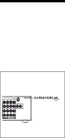
•The instructions in this manual are for model STR-DG920. Check your model number by looking at the lower right corner of the front panel. In this manual, models of area code U is used for illustration purposes unless stated otherwise. Any difference in operation is clearly indicated in the text, for example, “Models of area code CA only”.
•The instructions in this manual describe the controls on the supplied remote. You can also use the controls on the receiver if they have the same or similar names as those on the remote.
•“Neural-THX” and “neural THX” introduced in the Operating Instructions and displayed on the GUI menu screen and on the display mean NeuralTHX Surround.
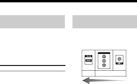
About area codes
The area code of the receiver you purchased is shown on the upper right portion of the rear panel (see the illustration below).
|
SURROUND BACK |
|
|
R |
|
L |
|
|
SURROUND |
CENTER |
Area code |
R |
|
L |
|
R |
FRONT B |
L |
|
|
FRONT A |
|
|
R |
|
L |
|
SPEAKERS
Any differences in operation, according to the area code, are clearly indicated in the text, for example, “Models of area code AA only”.
This receiver incorporates Dolby* Digital and Pro Logic Surround and the DTS** Digital Surround System.
*Manufactured under license from Dolby Laboratories. Dolby, Pro Logic, Surround EX and the double-D symbol are trademarks of Dolby Laboratories.
**Manufactured under license under U.S. Patent #’s: 5,451,942; 5,956,674; 5,974,380; 5,978,762; 6,226,616; 6,487,535 & other U.S. and worldwide patents issued & pending. DTS is a registered trademark and the DTS logos, Symbol, DTS-HD and DTS-HD Master Audio are trademarks of DTS, Inc. © 1996-2007 DTS, Inc. All Rights Reserved.
This receiver incorporates High-Definition Multimedia Interface (HDMITM) technology. HDMI, the HDMI logo and High-Definition Multimedia Interface are trademarks or registered trademarks of HDMI Licensing LLC.
XM Ready® is a registered trademark of XM Satellite Radio Inc. All rights reserved.
The font type (Shin Go R) installed in this receiver is provided by MORISAWA & COMPANY LTD. These names are the trademarks of MORISAWA & COMPANY LTD., and the copyright of the font also belongs to MORISAWA & COMPANY LTD.
This product is manufactured under license from Neural Audio Corporation and THX Ltd. Sony Corporation hereby grants the user a non-exclusive, non-transferable, limited right of use to this product under USA and foreign patent, patent pending and other technology or trademarks owned by Neural Audio Corporation and THX Ltd. “Neural Surround”, “Neural Audio”, “Neural” and “NRL” are trademarks and logos owned by Neural Audio Corporation, THX is a trademark of THX Ltd., which may be registered in some jurisdictions. All rights reserved.
iPod is a trademark of Apple Inc., registered in the U.S. and other countries.
All other trademarks and registered trademarks are of their respective holders. In this manual, ™ and ® marks are not specified.
The Bluetooth word mark and logos are owned by the Bluetooth SIG, Inc. and any use of such marks by Sony Corporation is under license.
Other trademarks and trade names are those of their respective owners.
“M-crew Server” is a trademark of Sony Corporation.
“x.v.Color” and “x.v.Color” logo are trademarks of Sony Corporation.
“BRAVIA” and 

 are trademarks of Sony Corporation.
3US

Table of Contents |
|
Getting Started |
|
Description and location of parts................... |
6 |
1: Installing speakers ................................... |
14 |
2: Connecting speakers................................ |
16 |
3: Connecting the TV .................................. |
18 |
4a: Connecting the audio components......... |
19 |
4b: Connecting the video components ........ |
24 |
5: Connecting the antennas (aerials)............ |
34 |
6: Preparing the receiver and the remote ..... |
35 |
7: Operating the receiver using the GUI |
|
(Graphical User Interface)...................... |
36 |
8: Selecting the speaker system................... |
39 |
9:Calibrating the appropriate speaker settings automatically
(Auto Calibration) .................................. |
39 |
Playback |
|
Selecting a component................................. |
44 |
Listening/Watching a component ................ |
46 |
Amplifier Operations |
|
Settings for the audio |
|
(Audio settings menu) ............................ |
48 |
Settings for the video |
|
(Video settings menu)............................. |
49 |
Settings for HDMI |
|
(HDMI settings menu)............................ |
49 |
Enjoying Surround Sound |
|
Enjoying a pre-programmed sound field ..... |
50 |
Resetting sound fields to the initial |
|
settings.................................................... |
55 |
Enjoying the surround effect at low |
|
volume levels (NIGHT MODE) ............. |
56 |
Advanced Speakers Setting
Up
Adjusting the speaker settings manually..... |
56 |
Adjusting the equalizer ............................... |
61 |
Tuner Operations |
|
Listening to FM/AM radio.......................... |
62 |
Listening to the XM Radio ......................... |
65 |
Control for HDMI |
|
Using the Control for HDMI function |
|
for “BRAVIA” Sync .............................. |
72 |
Preparing Control for HDMI function ........ |
74 |
Watching a DVD (One-Touch Play) ........... |
75 |
Enjoying the TV sound from the speakers |
|
connected to the receiver |
|
(System Audio Control)......................... |
76 |
Turning off the receiver with the TV |
|
(System Power Off) ............................... |
76 |
Other Operations |
|
Converting analog video input signals........ |
77 |
Enjoying the DIGITAL MEDIA PORT |
|
(DMPORT) ............................................ |
77 |
Naming inputs............................................. |
81 |
Switching between digital and analog |
|
audio (INPUT MODE) .......................... |
81 |
Enjoying the sound/images from |
|
other inputs ............................................ |
82 |
Changing the display .................................. |
84 |
Using the Sleep Timer ................................ |
87 |
Recording using the receiver....................... |
88 |
Operating without connecting to the TV .... |
89 |
4US

Using the Remote |
|
Programming the remote............................. |
99 |
Clearing all the contents of the remote’s |
|
memory ................................................ |
104 |
Additional Information |
|
Glossary .................................................... |
104 |
Precautions ................................................ |
108 |
Troubleshooting ........................................ |
109 |
Specifications ............................................ |
114 |
Index.............................................. |
Back cover |
5US
Getting Started
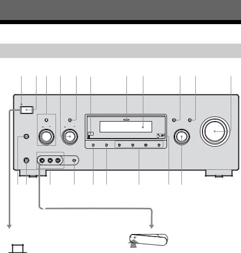
Description and location of parts
Front panel
1 2 3 4 5 6 |
7 8 |
9 q; |
qa |
||
ON/STANDBY |
|
|
|
|
|
POWER |
|
|
|
|
|
|
|
|
|
|
MASTER VOLUME |
TONE MODE |
TUNING MODE |
|
DISPLAY |
INPUT MODE |
|
|
|
MULTI CHANNEL DECODING |
|
|
|
TONE |
TUNING |
|
INPUT SELECTOR |
|
|
SPEAKERS |
|
|
|
|
|
(OFF/A/B/A+B) |
|
|
|
|
|
MEMORY/ |
DIMMER |
2CH/ |
A.F.D. |
MOVIE |
MUSIC |
ENTER |
A.DIRECT |
VIDEO 2 IN/PORTABLE AV IN
PHONES |
|
|
VIDEO |
L AUDIO R |
AUTO CAL MIC |
w; ql qk qj qh qg qf qd qs
Status of the POWER button
x (Off)
The receiver is turned off (initial setting). Press POWER to turn the receiver on. You cannot turn the receiver on using the remote.
x |
|
|
|
(On/Standby) |
Press ?/1 on the remote to turn the receiver on or set it to the standby mode.
When you press POWER on the receiver, the receiver will be turned off.
To remove the cover
Press PUSH.
When you remove the cover, keep it out of reach from children.
6US

Name Function
A ON/STANDBY Lights up in green when the lamp receiver is turned on.
Lights up in red when the receiver is set to standby mode.
B POWER |
Press to turn the receiver on |
|
or off (page 6, 35, 46, 47, |
|
55). |
CTONE MODE TONE +/–
Adjusts the tonal quality (bass/treble level) of the front, center and surround speakers.
Press TONE MODE repeatedly to select bass or treble level, then turn TONE +/– to adjust the level (page 90).
D TUNING +/– |
Turn to scan a station (page |
|
96, 98). |
|
|
E TUNING MODE |
Press to select the tuning |
|
mode (page 96, 99, 114). |
|
|
F Remote sensor |
Receives signals from |
|
remote commander. |
|
|
G MULTI |
Lights up when multi |
CHANNEL |
channel audio signals are |
DECODING lamp decoded (page 47). |
|
|
|
H Display |
The current status of the |
|
selected component or a list |
|
of selectable items appears |
|
here (page 85). |
|
|
I DISPLAY |
Press to select information |
|
displayed on the display |
|
(page 84, 113). |
|
|
J INPUT MODE |
Press to select the input |
|
mode when the same |
|
components are connected |
|
to both digital and analog |
|
jacks (page 81). |
|
|
K MASTER |
Turn to adjust the volume |
VOLUME |
level of all speakers at the |
|
same time (page 45, 46, |
|
47). |
|
|
L INPUT |
Turn to select the input |
SELECTOR |
source to playback (page |
|
44). |
MDigital Cinema Lights up when a sound Sound lamp field with DCS is
selected (page 54).
Name |
Function |
|
N 2CH/A.DIRECT |
Press to select a sound field |
|
|
|
(page 96). |
|
A.F.D. |
|
|
|
|
|
|
|
|
MOVIE |
|
|
|
|
|
MUSIC |
|
|
|
|
O DIMMER |
Press to adjust the |
|
|
|
brightness of the display |
|
|
(page 93). |
|
|
|
P MEMORY/ |
Press to store a station or |
|
|
ENTER |
enter the selection when |
|
|
selecting the settings |
|
|
(page 97). |
|
|
|
Q AUTO CAL MIC |
Connects to the supplied |
|
|
jack |
optimizer microphone for |
|
|
the Auto Calibration |
|
|
function (page 40). |
|
|
|
R VIDEO 2 IN/ |
Connects to a portable |
|
|
PORTABLE AV |
audio/video component |
|
IN jacks |
such as a camcorder or |
|
|
video game (page 30, 45). |
|
|
|
S PHONES jack |
Connects to headphones |
|
|
|
(page 109). |
|
|
|
T SPEAKERS |
Press to select the speaker |
|
|
(OFF/A/B/A+B) |
system (page 39). |
|
|
|
Started Getting
7US
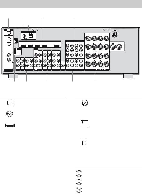
Rear panel
1 |
2 |
1 |
3 |
TV
OPTICAL
IN
OPTICAL
VIDEO 1
IN
SAT
IN
COAXIAL
DVD
IN
SA-CD/
CD
IN
DIGITAL
ASSIGNABLE
ANTENNA
FM AM
XM
HDMI
SAT IN BD IN DVD IN VIDEO 1 IN OUT
|
DMPORT |
|
|
|
MONITOR |
|
|
|
|
|
|
|
|
|
|
VIDEO |
VIDEO |
VIDEO |
VIDEO |
VIDEO |
VIDEO |
|
DC5V |
|
|
|
OUT |
IN |
IN |
IN |
OUT |
IN |
|
0.7A MAX |
|
|
|
|
|
|
|
|
|
|
|
|
|
|
|
AUDIO |
AUDIO |
AUDIO |
AUDIO |
AUDIO |
SIGNAL |
IN |
IN |
OUT |
IN |
IN |
IN |
IN |
IN |
OUT |
IN |
|
|
|
|
|
|
|
|
|
|
|
GND |
L |
|
|
L |
|
L |
|
L |
|
L |
|
|
|
|
|
|
|
|
|
|
AUDIO |
|
|
|
|
|
|
|
|
|
|
OUT |
|
R |
|
|
R |
|
R |
|
R |
|
R |
|
PHONO SA-CD/CD |
MD/TAPE |
TV |
SAT |
DVD |
BD |
VIDEO 1 SUBWOOFER |
|||
7 5 6
COMPONENT VIDEO
MONITOR |
COMPO 3 |
COMPO 2 |
COMPO 1 |
OUT |
IN |
IN |
IN |
Y
PB/
CB
PR/
CR
ASSIGNABLE (INPUT ONLY)
L  L
L
CENTER
R  R
R
FRONT SURROUND SUR BACK SUBWOOFER
MULTI CHANNEL INPUT
5
|
SURROUND BACK |
|
R |
|
L |
|
SURROUND |
CENTER |
R |
|
L |
R |
FRONT B |
L |
|
||
|
FRONT A |
|
R |
|
L |
SPEAKERS
4
ADIGITAL INPUT/OUTPUT section
|
|
|
|
OPTICAL IN |
Connects to a DVD |
|
|
|
|||
|
|
|
|
jacks |
player, etc. The |
|
|
|
|
|
COAXIAL jack |
|
|
|
|
|
|
|
|
|
|
COAXIAL IN |
provides a better |
|
|
|
|
jacks |
quality sound (page |
|
|
|
|
|
20, 27, 29). |
|
|
|
|
|
|
|
|
|
|
HDMI IN/ |
Connects to a DVD |
|
|
|
|
OUT* jacks |
player, satellite |
|
|
|
|
|
tuner, or a Blu-ray |
|
|
|
|
|
disc player. The |
|
|
|
|
|
image is output to a |
|
|
|
|
|
TV or a projector |
|
|
|
|
|
while the sound can |
|
|
|
|
|
be output from a TV |
|
|
|
|
|
or/and speakers |
|
|
|
|
|
connected to this |
|
|
|
|
|
receiver (page 25). |
|
|
|
|
|
|
BANTENNA section
|
|
|
|
|
FM |
Connects to the FM |
|
|
|
|
|
ANTENNA |
wire antenna |
|
|
|
|
|
jack |
(aerial) supplied |
|
|
|
|
|
|
with this receiver |
|
|
|
|
|
|
(page 34). |
|
|
|
|
|
|
|
|
|
|
|
|
AM |
Connects to the AM |
|
|
|
|
|
ANTENNA |
loop antenna |
|
|
|
|
|
||
|
|
|
|
|
terminals |
(aerial) supplied |
|
|
|
||||
|
|
|
|
|||
|
|
|
|
|
|
with this receiver |
|
|
|
|
|
|
(page 34). |
|
|
|
|
|
|
|
|
|
|
|
|
XM jack |
Connects to the XM |
|
|
|
|
|
|
Mini-Tuner and |
|
|
|
|
|
|
Home Dock (not |
|
|
|
|
|
|
supplied) (page 66). |
|
|
|
|
|
|
|
CCOMPONENT VIDEO INPUT/ OUTPUT section
Green
(Y)
Blue
(PB/CB)
Red
(PR/CR)
Y, PB/CB, PR/CR IN/ OUT* jacks
Connects to a DVD player, TV, satellite tuner, etc. (page18, 27, 29).
8US
DSPEAKERS section
Connects to speakers (page 16).
EAUDIO INPUT/OUTPUT section
|
White (L) |
AUDIO IN/ |
Connects to a Super |
|
OUT jacks |
Audio CD player, |
|
|
|
|
etc. (page 18, 20, |
|
Red (R) |
|
23). |
|
|
MULTI |
Connect to a Super |
L |
L |
CHANNEL |
Audio CD player, |
|
CENTER |
||
R |
R |
INPUT jacks |
etc. with an analog |
FRONT SURROUND SUR BACK SUBWOOFER |
|
audio jack for 7.1 |
|
MULTI CHANNEL INPUT |
|
||
|
|
|
channel or 5.1 |
|
|
|
channel sound (page |
|
|
|
22). |
|
Black |
AUDIO OUT Connects to |
|
|
jack |
subwoofer (page |
|
|
|
||
|
|
|
16). |
FVIDEO/AUDIO INPUT/OUTPUT section
AUDIO IN/ |
Connects to a VCR, |
White (L) OUT jacks |
DVD player, etc. |
(page 27–30).
 Red (R)
VIDEO IN/
Yellow |
OUT* jacks |
|
GDMPORT
|
|
DMPORT |
Connects to a |
|
|
||
|
|
jack |
DIGITAL MEDIA |
|
|
|
PORT adapter |
|
|
|
(page 20). |
|
|
|
|
|
|
|
|
|
|
|
|
*You can watch the selected input image when you connect the MONITOR OUT or HDMI OUT jack to a TV (page 18). You can operate this receiver using a GUI (Graphical User Interface) (page 36).
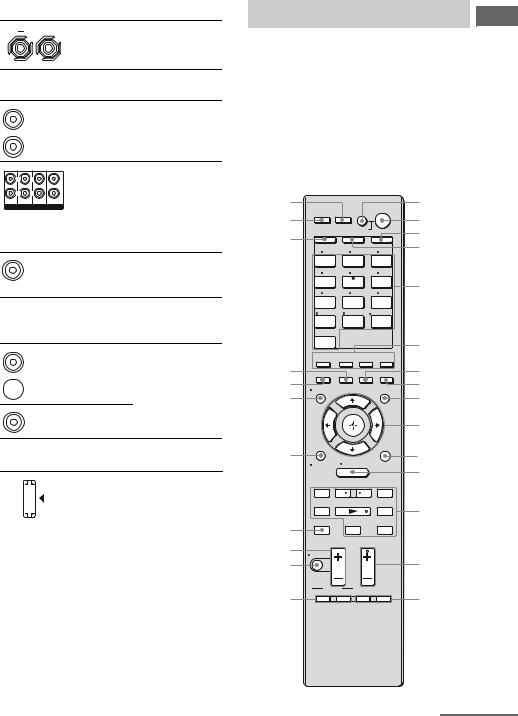
Remote commander
You can use the supplied remote to operate the receiver and to control the Sony audio/video components that the remote is assigned to operate.
You can also program the remote to control non-Sony audio/video components. For details, see “Programming the remote” (page 99).
RM-AAP023 |
|
|
|
|
|
wh |
|
|
|
?/1 |
1 |
wg |
THEATER RM SET UP AV ?/1 |
2 |
|||
|
|
|
|
||
|
SYSTEM STANDBY |
AMP |
3 |
||
wf |
SHIFT |
TV |
|
||
|
|
|
|
4 |
|
|
1 |
2 |
|
3 |
|
|
VIDEO 1 |
VIDEO 2 |
BD |
|
|
|
4 |
5 |
|
6 |
|
|
DVD |
SAT |
|
TV |
5 |
|
7 |
8 |
|
9 |
|
|
|
|
|||
|
MD/ |
SA-CD/ |
TUNER |
|
|
|
TAPE |
CD |
|
|
|
|
|
|
|
||
|
-/-- |
0/10 |
ENT/MEM |
|
|
|
PHONO |
MULTI IN |
DMPORT |
|
|
|
CLEAR/>10 |
|
|
|
|
|
XM |
|
|
|
6 |
|
|
|
|
|
|
|
2CH/ |
A.F.D. |
MOVIE |
MUSIC |
|
|
A.DIRECT |
|
|||
wd |
RESOLUTION |
INPUT |
SLEEP |
NIGHT |
7 |
ws |
MODE |
MODE |
8 |
||
DISPLAY |
|
|
GUI |
||
wa |
|
|
MODE |
9 |
|
|
|
|
|
||
|
|
|
|
|
0 |
w; |
O |
HOME |
|
qa |
|
|
RETURN/ |
OPTIONS |
qs |
||
|
EXIT |
MENU |
TOOLS |
||
|
|
|
|||
|
– CATEGORY + |
|
|
||
|
. < |
< |
> |
|
|
|
TUNING – CATEGORY MODE |
TUNING + |
qd |
||
|
m |
|
|
M |
|
|
|
|
|
|
|
ql |
DISC SKIP |
|
|
D.TUNING |
|
|
X |
|
x |
|
|
TV VOL |
TV CH |
|
|||
|
|
||||
qk |
MASTER VOL |
PRESET |
|
||
MUTING |
|
|
|
|
|
qj |
|
|
|
qf |
|
|
|
|
|
||
|
BD/DVD |
F1 |
F2 |
|
|
qh |
TOP MENU MENU |
qg |
|||
TV INPUT WIDE |
|
|
|||
|
|
|
|
||
|
|
|
|
continued |
|
Started Getting
9US

Name |
Function |
A AV ?/1 |
Press to turn on or off the |
(on/standby) |
audio/video components that |
|
the remote is programmed to |
|
operate. |
|
To turn the TV on or off, press |
|
TV (D) and then press AV |
|
?/1. |
|
If you press ?/1 (B) at the |
|
same time, it will turn off the |
|
receiver and other components |
|
(SYSTEM STANDBY). |
|
Note |
|
The function of the AV ?/1 |
|
switch changes automatically |
|
each time you press the input |
|
buttons (E). |
|
|
B ?/1 |
Press to turn the receiver on or |
(on/standby) |
set it to the standby mode. |
|
To turn off all components, |
|
press ?/1 and AV ?/1 (A) at |
|
the same time (SYSTEM |
|
STANDBY). |
|
Saving the power in |
|
standby mode. |
|
When “Control for HDMI” is |
|
set to “OFF” (page 75). |
|
|
C AMP |
Press to enable the receiver |
|
operation (page 89). |
|
|
D TV |
Press to light up the button. It |
|
changes the remote key |
|
function to activate the buttons |
with yellow printing. It also activate the DISPLAY (U), OPTIONS TOOLS (K), HOME/MENU (L), RETURN/EXIT O (T),  (J), and V/v/B/b (J) buttons to perform menu operations for Sony TVs only.
E Input buttons Press one of the buttons to select the component you want to use. When you press any of the input buttons, the receiver turns on. The buttons are factory assigned to control Sony components (page 45). You can program the remote to control non-Sony components following the steps in “Programming the remote” on page 99.
Name Function
Numeric Press SHIFT (X), then press buttons numeric buttons to
(number 5*) – preset/tune to preset stations.
–select track numbers of the CD player, VCD player, LD player, DVD player, MD deck, DAT deck, or tape deck. Press 0/10 to select track number 10.
–select channel numbers of the VCR, satellite tuner, Bluray disc player, PSX, DVD/ VHS COMBO, or DVD/
HDD COMBO.
Press TV (D) and then press the numeric buttons to select the TV channels.
ENT/MEM Press SHIFT (X), then press ENT/MEM to
–enter the value after selecting a channel, disc or track using the numeric buttons of the VCR, CD player, DVD player, LD player, MD deck, DAT deck, tape deck, satellite tuner, Blu-ray disc player, PSX, DVD/VHS COMBO, or DVD/HDD COMBO.
–store a station during tuner
operation.
To enter the value of Sony TV, press TV (D) and then press ENT/MEM.
CLEAR Press SHIFT (X), then press CLEAR to
–clear a mistake when you press the incorrect numeric button of the DVD player, Blu-ray disc player, PSX, satellite tuner, DVD/VHS COMBO, or DVD/HDD COMBO.
–return to continuous playback, etc. of the satellite tuner or DVD player.
10US
Name |
Function |
|
-/-- |
Press SHIFT (X), then press |
|
|
|
-/-- to select the channel entry |
|
|
mode, either one or two digit |
|
|
of the VCR or satellite tuner. |
|
|
To select the channel entry |
|
|
mode of the TV, press TV |
|
|
(D) and then press -/--. |
|
|
|
>10 |
Press SHIFT (X), then press |
|
|
|
>10 to |
|
|
– select track numbers over 10 |
|
|
of the CD player, VCD |
|
|
player, LD player, MD |
|
|
deck, tape deck, TV, VCR, |
|
|
or satellite tuner. |
|
|
– select channel numbers of |
|
|
the Digital CATV terminal. |
|
|
|
F 2CH/ |
Press to select a sound field |
|
|
A.DIRECT |
(page 96). |
|
|
|
|
A.F.D. |
|
|
|
|
|
MOVIE |
|
|
|
|
|
MUSIC |
|
|
|
|
G SLEEP |
Press to activate the Sleep |
|
|
|
Timer function and the |
|
|
duration which the receiver |
|
|
turns off automatically |
|
|
(page 87). |
|
|
|
H NIGHT MODE |
Press to activate the NIGHT |
|
|
|
MODE function (page 56). |
|
|
|
I GUI MODE |
Press to display the GUI menu |
|
|
|
on the TV screen. |
J
,
V/v/B/b
After pressing AMP (C), press MENU (L) for receiver operation, then press V/v/B /b to select the settings.
After pressing BD/DVD TOP MENU (P) or BD/DVD MENU (P), press V/v/B/b to select the settings, and then press  to enter the selection.
Press  also to enter the selection of the receiver, VCR, satellite tuner, DVD player, Blu-ray disc player, PSX, DVD/VHS COMBO, or DVD/HDD COMBO.
Name Function
K OPTIONS Press to display and select TOOLS items from the option
menus for receiver, DVD player, Blu-ray disc player or satellite tuner.
Press TV (D) and then press TOOLS to display the options of Sony TV.
L HOME/MENU Press to display the menu to operate the audio/video components.
Then, use V/v/B/b (J) and  (J) to perform menu operations.
To display the menus of Sony TV, press TV (D) and then press HOME/ MENU.
M ./> |
Press to skip tracks of the |
|
|
|
VCR, CD player, VCD |
|
|
player, LD player, DVD |
|
|
player, MD deck, DAT |
|
|
deck, tape deck, Blu-ray |
|
|
disc player, PSX, DVD/ |
|
|
VHS COMBO, or DVD/ |
|
|
HDD COMBO. |
|
|
|
|
m/M |
Press to |
|
|
– search tracks in the |
|
|
forward/backward |
|
|
direction of the CD |
|
|
player, VCD player, DVD |
|
|
player, LD player, MD |
|
|
deck, Blu-ray disc player, |
|
|
PSX, DVD/VHS |
|
|
COMBO, or DVD/HDD |
|
|
COMBO. |
|
|
– fast forward/rewind of the |
|
|
VCR, DAT deck, or tape |
|
|
deck. |
|
|
|
|
N* |
Press to start playback of |
|
|
the VCR, CD player, VCD |
|
|
player, LD player, DVD |
|
|
player, MD deck, DAT |
|
|
deck, tape deck, Blu-ray |
|
|
disc player, PSX, DVD/ |
|
|
VHS COMBO, or DVD/ |
|
|
HDD COMBO. |
|
|
|
Started Getting
continued
11US

Name Function
XPress to pause playback or recording of the VCR, CD player, VCD player, LD player, DVD player, MD deck, DAT deck, tape deck, Blu-ray disc player, PSX, DVD/VHS COMBO, or DVD/HDD COMBO. (Also starts recording with components in recording standby.)
xPress to stop playback of the VCR, CD player, VCD player, LD player, DVD player, MD deck, DAT deck, tape deck, Blu-ray disc player, PSX, DVD/VHS COMBO, or DVD/HDD COMBO.
|
TUNING +/– |
Press to scan a station. |
|
CATEGORY |
Press to select the category |
|
MODE |
mode for XM Radio (page |
|
|
98). |
|
|
|
|
CATEGORY |
Press to select a category for |
|
+/– |
XM Radio (page 98). |
|
|
|
|
D.TUNING |
Press to enter direct tuning |
|
|
mode (page 96). |
|
|
|
N TV CH +/– |
Press TV (D) and then press |
|
|
|
TV CH +/– to select preset TV |
|
|
channels. |
|
|
|
|
PRESET |
Press to |
|
+*/– |
– select preset stations. |
|
|
– select preset channels of the |
|
|
VCR, satellite tuner, |
|
|
Blu-ray disc player, DVD |
|
|
player, LD player, DVD/ |
|
|
VHS COMBO, or DVD/ |
|
|
HDD COMBO. |
|
|
|
O F1, F2 |
Press F1 or F2 to select a |
|
|
|
component. |
|
|
• DVD/HDD COMBO |
|
|
F1: HDD mode |
|
|
F2: DVD mode |
|
|
• DVD/VHS COMBO |
|
|
F1: DVD mode |
|
|
F2: VHS mode |
|
|
|
Name |
Function |
|
P BD/DVD TOP |
Press to display the menu or |
|
|
MENU |
on-screen guide of the DVD |
|
|
player, Blu-ray disc player, |
|
|
PSX, DVD/VHS COMBO, or |
|
|
DVD/HDD COMBO on the |
|
|
TV screen. Then, use V/v/B/ |
|
|
b (J) and (J) to |
|
|
perform menu operations. |
|
|
|
|
BD/DVD |
Press to display the menu of |
|
MENU |
the DVD player or Blu-ray |
|
|
disc player on the TV screen. |
|
|
Then, use V/v/B/b (J) and |
|
|
(J) to perform menu |
|
|
operations. |
|
|
|
|
TV INPUT |
Press TV (D) and then press |
|
|
TV INPUT to select the input |
|
|
signal (TV input or video |
|
|
input). |
|
|
|
|
WIDE |
Press TV (D) and then press |
|
|
WIDE to select the wide |
|
|
picture mode. |
|
|
|
Q MUTING |
Press to turn off the sound |
|
|
|
temporarily. Press the button |
|
|
again to restore the sound. |
|
|
To mute the sound of the TV, |
|
|
press TV (D) and then press |
|
|
MUTING. |
|
|
|
R TV VOL +/– |
Press TV (D) and then press |
|
|
|
TV VOL +/– to adjust the TV |
|
|
volume level. |
|
|
|
|
MASTER |
Press to adjust the volume |
|
VOL +/– |
level of all speakers at the |
|
|
same time. |
|
|
|
S DISC SKIP |
Press to skip disc when using |
|
|
|
a multi-disc changer. |
|
|
|
T RETURN/ |
Press to |
|
|
EXIT O |
– return to the previous menu. |
|
|
– exit the menu while the |
|
|
menu or on-screen guide of |
|
|
the VCD player, LD player, |
|
|
DVD player, Blu-ray disc |
|
|
player, PSX, DVD/VHS |
|
|
COMBO, or satellite tuner |
|
|
is displayed on the TV |
|
|
screen. |
|
|
To return to the previous |
|
|
menu of Sony TV, press TV |
|
|
(D) and then press |
|
|
RETURN/EXIT O. |
|
|
|
12US

Name Function
U DISPLAY Press to select information displayed in the display, TV screen of the VCR, VCD player, LD player, DVD player, CD player, MD deck, Blu-ray disc player, PSX, satellite tuner, DVD/VHS COMBO, or DVD/HDD COMBO.
To select information of Sony TV, press TV (D) and then press DISPLAY.
V RESOLUTION Press to change the resolution of signals output from the HDMI OUT or COMPONENT VIDEO MONITOR OUT jack
(page 77).
W INPUT MODE Press to select the input mode when the same components are connected to both digital and analog jacks (page 81).
X SHIFT |
Press to light up the button. It |
|
changes the remote button |
|
function to activate the |
|
buttons with pink printing. |
Y THEATER Press to enjoy optimal image suited for movies and to output the sound from the speakers connected to this receiver automatically.
Note
This button will only function if your TV is compatible with Theater Mode.
For details, refer to the operating instructions supplied with the TV.
Z RM SET UP Press to set up the remote.
*The number 5, PRESET + and N buttons have tactile dots. Use the tactile dots as references when operating the receiver.
Notes
•Some functions explained in this section may not work depending on the model.
•The above explanation is intended to serve as an example only. Therefore, depending on the component, the above operation may not be possible or may operate differently than described.
Started Getting
13US

1: Installing speakers
This receiver allows you to use a 7.1 channel system (7 speakers and one subwoofer).
Enjoying a 5.1/7.1 channel system
To fully enjoy theater-like multi channel surround sound requires five speakers (two front speakers, a center speaker, and two surround speakers) and a subwoofer (5.1 channel).
Example of a 5.1 channel speaker system configuration
AFront speaker (left)
BFront speaker (right)
CCenter speaker
DSurround speaker (left)
ESurround speaker (right)
HSubwoofer
You can enjoy high fidelity reproduction of DVD software recorded sound in the Surround EX format if you connect one additional surround back speaker (6.1 channel system) or two surround back speakers (7.1 channel system).
Example of a 7.1 channel speaker system configuration
AFront speaker (left)
BFront speaker (right)
CCenter speaker
DSurround speaker (left)
ESurround speaker (right)
FSurround back speaker (left)
GSurround back speaker (right)
HSubwoofer
14US
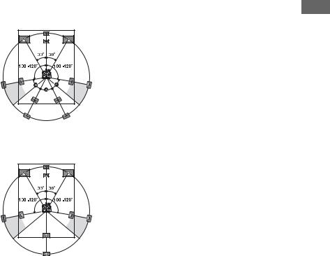
Tips
• When you connect a 7.1 channel speaker system, the angle A should be the same.
Started Getting
•When you connect a 6.1 channel speaker system, place the surround back speaker behind the listening position.
•Since the subwoofer does not emit highly directional signals, you can place it wherever you want.
15US

2: Connecting speakers
Before connecting cords, make sure to disconnect the AC power cord (mains lead).
H |
E |
A |
|
G |
B
F |
D |
NA
AM |
SURROUND BACK |
R |
L |
HDMI |
|
|
|
COMPONENT VIDEO |
|
|
||||
|
|
|
MONITOR |
COMPO 3 |
COMPO 2 |
COMPO 1 |
SURROUND |
CENTER |
||
BD IN |
DVD IN |
VIDEO 1 IN |
OUT |
|||||||
OUT |
IN |
IN |
IN |
R |
L |
|||||
|
|
|
|
|
|
|
|
|||
|
|
|
|
|
|
|
|
Y |
|
|
|
MONITOR |
|
|
|
|
|
PB/ |
|
|
|
VIDEO |
VIDEO |
VIDEO |
VIDEO |
VIDEO |
VIDEO |
CB |
FRONT B |
|
|
R |
L |
|||||||
|
OUT |
IN |
IN |
IN |
OUT |
IN |
|
||
|
|
|
|
|
|
|
PR/ |
|
|
|
|
|
|
|
|
|
CR |
|
|
|
|
AUDIO |
AUDIO |
AUDIO |
AUDIO |
AUDIO |
ASSIGNABLE (INPUT ONLY) |
|
|
IN |
IN |
IN |
IN |
IN |
OUT |
IN |
|
|
|
L |
L |
L |
L |
L |
|
FRONT A |
|
R |
L |
||||||
|
|
AUDIO |
|
|
|||
|
|
OUT |
|
CENTER |
|
|
|
R |
R |
R |
R |
R |
|
|
|
|
|
|
FRONT SURROUND SUR BACK SUBWOOFER |
|
|
||
APE TV |
SAT DVD BD |
VIDEO 1 SUBWOOFER |
MULTI CHANNEL INPUT |
SPEAKERS |
|
||
|
SPEAKERS FRONT B |
|
13/32 in. |
terminalsa) |
B |
(10 mm) |
|
|
B |
A |
C |
AMonaural audio cord (not supplied) BSpeaker cord (not supplied)
AFront speaker A (left)
BFront speaker A (right)
CCenter speaker
DSurround speaker (left)
ESurround speaker (right) FSurround back speaker (left)b) GSurround back speaker (right)b) HSubwooferc)
16US

a)If you have an additional front speaker system, connect them to the SPEAKERS FRONT B terminals. You can select the front speakers you want to use with the SPEAKERS (OFF/A/B/A+B) button on the receiver (page 39).
b)If you connect only one surround back speaker, connect it to the SPEAKERS SURROUND BACK L terminals.
c)When you connect a subwoofer with an auto standby function, turn off the function when watching movies. If the auto standby function is set to on, it turns to standby mode automatically based on the level of the input signal to a subwoofer, then sound may not be output.
Note
Before connecting the AC power cord (mains lead), make sure that metallic wires of the speaker cords are not touching each other between the SPEAKERS terminals.
Started Getting
17US
3: Connecting the TV
You can watch the selected input image when you connect the HDMI OUT or MONITOR OUT jack to a TV. You can operate this receiver using a GUI (Graphical User Interface).
It is not necessary to connect all the cables. Connect audio and video cords according to the jacks of your components.
|
TV |
|
Audio signals |
Audio/video |
Video signals |
|
signals |
|
A |
B |
|
|
C |
|
|
|
|
D |
|
|
|
|
E |
|
|
||
|
TV |
|
|
|
|
|
|
|
|
|
|
|
|
|
|
|
|
|
|
OPTICAL |
|
|
ANTENNA |
|
|
|
|
|
|
|
|
|
|
|
|
|
|
|
IN |
|
|
|
|
|
|
|
|
|
|
|
|
|
|
|
||
|
|
FM |
|
AM |
|
|
|
|
|
|
|
|
|
|
|
SURROUND BACK |
|
|
|
|
|
|
|
|
|
|
|
|
|
|
|
|
|
|
|
|
|
|
OPTICAL |
|
|
|
|
|
|
|
|
|
|
|
|
|
|
R |
|
L |
|
|
|
|
|
|
|
|
|
|
|
|
|
|
|
|
|
|
|
|
VIDEO 1 |
XM |
|
|
|
|
|
|
|
|
|
|
|
|
|
|
|
|
|
IN |
|
|
|
|
|
|
|
|
|
|
|
|
|
|
|
|
|
|
|
|
|
|
|
HDMI |
|
|
|
|
|
COMPONENT VIDEO |
|
|
|
|||
|
|
|
|
|
|
|
|
|
|
|
MONITOR |
COMPO 3 |
COMPO 2 |
COMPO 1 |
|
SURROUND |
|
|
|
|
|
SAT IN |
BD IN |
DVD IN |
VIDEO 1 IN |
|
OUT |
|
|
||||||||
|
SAT |
|
|
OUT |
IN |
IN |
IN |
R |
|
L |
||||||||
|
IN |
|
|
|
|
|
|
|
|
|
|
|
|
|
Y |
|
||
|
|
|
|
|
|
|
|
|
|
|
|
|
|
|
|
|
|
|
|
|
DMPORT |
|
|
MONITOR |
|
|
|
|
|
|
|
|
|
|
|
||
|
|
|
|
|
|
|
|
|
|
|
|
|
PB/ |
|
|
|
||
|
|
|
|
|
|
VIDEO |
VIDEO |
VIDEO |
VIDEO |
VIDEO |
VIDEO |
|
|
|
CB |
|
FRONT B |
|
|
|
|
|
|
|
|
|
|
|
R |
L |
|||||||
|
COAXIAL |
DC5V |
|
|
OUT |
IN |
IN |
IN |
OUT |
IN |
|
|
|
|
|
|||
|
DVD |
0.7A MAX |
|
|
|
|
|
|
|
|
|
|
|
PR/ |
|
|
|
|
|
|
|
|
|
|
|
|
|
|
|
|
|
|
|
|
|
||
|
IN |
|
|
|
|
|
|
|
|
|
|
|
|
|
CR |
|
|
|
|
|
|
|
|
|
|
AUDIO |
AUDIO |
AUDIO |
AUDIO |
AUDIO |
|
ASSIGNABLE (INPUT ONLY) |
|
|
|
||
|
SA-CD/ |
IN |
IN |
OUT |
IN |
IN |
IN |
IN |
IN |
OUT |
IN |
|
|
|
|
|
|
|
|
CD |
SIGNAL |
L |
|
L |
|
L |
|
L |
|
L |
|
L |
L |
|
|
FRONT A |
|
|
IN |
GND |
|
|
|
|
|
|
R |
|
L |
|||||||
|
|
|
|
|
|
|
|
|
|
|
AUDIO |
|
|
|
|
|
||
|
|
|
|
|
|
|
|
|
|
|
OUT |
|
|
|
CENTER |
|
|
|
|
|
|
R |
|
R |
|
R |
|
R |
|
R |
|
R |
R |
|
|
|
|
|
|
|
|
|
|
|
|
|
|
|
|
FRONT |
SURROUND SUR BACK |
SUBWOOFER |
|
|
|
|
|
DIGITAL |
PHONO SA-CD/CD |
MD/TAPE |
TV |
SAT |
DVD |
BD |
VIDEO 1 SUBWOOFER |
MULTI CHANNEL INPUT |
SPEAKERS |
|
|||||||
|
ASSIGNABLE |
|
|
|
|
|
|
|
|
|
|
|
|
|
|
|
|
|
AOptical digital cord (not supplied)
BAudio cord (not supplied)
CHDMI cable (not supplied)
We recommend that you use a Sony HDMI cable.
DVideo cord (not supplied)
EComponent video cord (not supplied)
18US

Notes
•Before connecting cords, make sure to disconnect the AC power cord (mains lead).
•Be sure to turn on the receiver when the video and audio of a playback component are being output to a TV via the receiver. If the power supply of the receiver is not turned on, neither video nor audio is transmitted.
•Depending on the status of the connection between the TV and the antenna (aerial), the image on the TV screen may be distorted. In this case, place the antenna (aerial) farther away from the receiver.
•When connecting optical digital cords, insert the plugs straight in until they click into place.
•Do not bend or tie optical digital cords.
Tips
•The receiver has a video conversion function. For details, see “Notes on converting video signals” (page 32).
•The sound of the TV is output from the speakers connected to the receiver if you connect the audio output jack of the TV to the TV IN jacks of the receiver. In this configuration, set the sound output jack of the TV to “Fixed” if it can be switched between either “Fixed” or “Variable”.
•All the digital audio jacks are compatible with 32 kHz, 44.1 kHz, 48 kHz, and 96 kHz sampling frequencies.
4a: Connecting the audio components
How to connect your components
This section describes how to connect your audio components to this receiver. Before you begin, refer to “Component to be connected” below for the pages which describe how to connect each component.
After connecting your audio component, proceed to “4b: Connecting the video components” (page 24) or “5: Connecting the antennas (aerials)” (page 34).
Component to be connected |
Page |
|
Super Audio CD |
With digital audio |
20 |
player, CD player |
output |
|
|
|
|
|
With multi channel |
22 |
|
audio output |
|
|
|
|
|
With analog audio |
23 |
|
output only |
|
|
|
|
MD deck, Tape deck, Analog disc |
23 |
|
turntable |
|
|
|
|
|
DIGITAL MEDIA PORT adapter |
20 |
|
|
|
|
Started Getting
19US
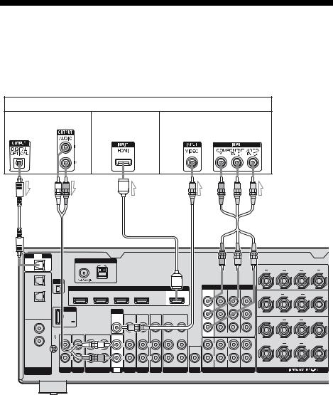
Connecting components with digital audio output jack
The following illustration shows how to connect a Super Audio CD player, CD player and DIGITAL MEDIA PORT adapter.
DIGITAL MEDIA PORT adapter
Super Audio CD player,
CD player
A 


 B
B
|
TV |
|
|
|
|
|
|
|
|
|
|
|
|
|
|
|
OPTICAL |
|
|
ANTENNA |
|
|
|
|
|
|
|
|
|
|
|
|
|
IN |
|
|
|
|
|
|
|
|
|
|
|
|
|
|
||
|
|
FM |
AM |
|
|
|
|
|
|
|
|
|
|
SURROUND BACK |
|
|
|
|
|
|
|
|
|
|
|
|
|
|
|
|
|
|
|
OPTICAL |
|
|
|
|
|
|
|
|
|
|
|
|
|
R |
|
L |
|
|
|
|
|
|
|
|
|
|
|
|
|
|
|
|
|
VIDEO 1 |
XM |
|
|
|
|
|
|
|
|
|
|
|
|
|
|
|
IN |
|
|
|
|
|
|
|
|
|
|
|
|
|
|
|
|
|
|
|
|
|
HDMI |
|
|
|
|
|
COMPONENT VIDEO |
|
|
|||
|
|
|
|
|
|
|
|
|
|
MONITOR |
COMPO 3 |
COMPO 2 |
COMPO 1 |
SURROUND |
|
|
|
|
|
SAT IN |
BD IN |
DVD IN |
VIDEO 1 IN |
|
OUT |
|
|||||||
SAT |
|
|
|
OUT |
IN |
IN |
IN |
|
|
|||||||
|
|
|
|
|
|
|
|
|
|
|
|
|
R |
|
L |
|
IN |
|
|
|
|
|
|
|
|
|
|
|
|
|
|
||
|
|
|
|
|
|
|
|
|
|
|
|
|
|
Y |
|
|
|
DMPORT |
|
|
MONITOR |
|
|
|
|
|
|
|
|
|
|
||
|
|
|
|
|
|
|
|
|
|
|
|
PB/ |
|
|
||
|
|
|
|
|
VIDEO |
VIDEO |
VIDEO |
VIDEO |
VIDEO |
VIDEO |
|
|
|
CB |
FRONT B |
|
|
|
|
|
|
|
|
|
R |
L |
|||||||
COAXIAL |
DC5V |
|
|
OUT |
IN |
IN |
IN |
OUT |
IN |
|
|
|
|
|||
DVD |
0.7A MAX |
|
|
|
|
|
|
|
|
|
|
|
PR/ |
|
|
|
|
|
|
|
|
|
|
|
|
|
|
|
|
|
|
||
IN |
|
|
|
|
|
|
|
|
|
|
|
|
|
CR |
|
|
|
|
|
|
|
|
AUDIO |
AUDIO |
AUDIO |
AUDIO |
AUDIO |
|
ASSIGNABLE (INPUT ONLY) |
|
|
||
SA-CD/ |
IN |
IN |
OUT |
IN |
IN |
IN |
IN |
IN |
OUT |
IN |
|
|
|
|
|
|
CD |
SIGNAL |
L |
|
L |
|
L |
|
L |
|
L |
|
L |
L |
|
FRONT A |
|
IN |
GND |
|
|
|
|
AUDIO |
R |
|
L |
|||||||
|
|
|
|
|
|
|
|
|
|
|
|
|
|
|||
|
|
|
|
|
|
|
|
|
|
|
OUT |
|
|
CENTER |
|
|
|
|
R |
|
R |
|
R |
|
R |
|
R |
|
R |
R |
|
|
|
FRONT SURROUND SUR BACK SUBWOOFER
DIGITAL |
PHONO SA-CD/CD MD/TAPE TV SAT DVD BD |
VIDEO 1 SUBWOOFER |
MULTI CHANNEL INPUT |
SPEAKERS |
ASSIGNABLE |
|
|
|
|
AAudio cord (not supplied)
BCoaxial digital cord (not supplied)
Notes
•Before connecting cords, make sure to disconnect the AC power cord (mains lead).
•When you play back a Super Audio CD disc on a Super Audio CD player, the sound is output only if you make the connection to MULTI CHANNEL INPUT or SA-CD/CD IN jacks (analog input jack) on the receiver. Refer to the operating instructions supplied with the Super Audio CD player.
Tip
All the digital audio jacks are compatible with 32 kHz, 44.1 kHz, 48 kHz, and 96 kHz sampling frequencies.
20US
Notes on connecting DIGITAL MEDIA PORT adapter
•When connecting the DIGITAL MEDIA PORT adapter, be sure the connector is inserted with the arrow mark facing towards the arrow mark on the DMPORT jack.
•Be sure to make DMPORT connections firmly, insert the connector straight in.
•As the connector of the DIGITAL MEDIA PORT adapter is fragile, be sure to handle with care when placing or moving the receiver.
•To disconnect the DIGITAL MEDIA PORT adapter, squeeze the sides of the connector, since the connector is locked in place.
If you want to connect several digital components, but cannot find an unused input
See “Enjoying the sound/images from other inputs” (page 82).
Started Getting
21US

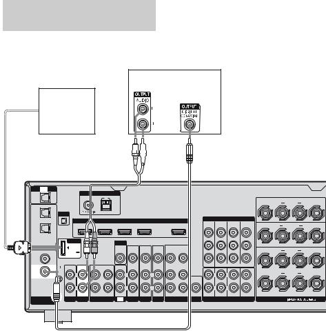
Connecting components with multi channel output jacks
If your DVD or Super Audio CD player is equipped with multi channel output jacks, you can connect them to the MULTI CHANNEL INPUT jacks of this receiver to enjoy multi channel sound. Alternatively, the multi channel input jacks can be used to connect an external multi channel decoder.
DVD player, Super Audio CD player, etc.
A


 B
B
TV
OPTICAL
IN
OPTICAL
VIDEO 1
IN
SAT
IN
COAXIAL
DVD
IN
SA-CD/
CD
IN
DIGITAL
ASSIGNABLE
XM
DMPORT
DC5V 0.7A MAX
ANTENNA
FM AM
HDMI
SAT IN BD IN DVD IN VIDEO 1 IN OUT
MONITOR
VIDEO |
VIDEO |
VIDEO |
VIDEO |
VIDEO |
VIDEO |
OUT |
IN |
IN |
IN |
OUT |
IN |
COMPONENT VIDEO
MONITOR |
COMPO 3 |
COMPO 2 |
COMPO 1 |
OUT |
IN |
IN |
IN |
Y
PB/
CB
PR/
CR
|
|
|
|
|
AUDIO |
AUDIO |
AUDIO |
AUDIO |
AUDIO |
|
ASSIGNABLE (INPUT ONLY) |
IN |
IN |
OUT |
IN |
IN |
IN |
IN |
IN |
OUT |
IN |
|
|
SIGNAL |
|
|
|
|
|
|
|
|
|
|
|
GND |
L |
|
L |
|
L |
|
L |
|
L |
L |
L |
|
|
|
|
|
|||||||
|
|
|
|
|
|
|
|
|
AUDIO |
|
|
|
|
|
|
|
|
|
|
|
OUT |
|
CENTER |
|
R |
|
R |
|
R |
|
R |
|
R |
R |
R |
|
|
|
|
|
|
|
|
|
|
FRONT SURROUND SUR BACK SUBWOOFER |
|
PHONO SA-CD/CD |
MD/TAPE |
TV |
SAT |
DVD |
BD |
VIDEO 1 SUBWOOFER |
MULTI CHANNEL INPUT |
||||
SURROUND BACK
R L
SURROUND
R L
FRONT B
R L
FRONT A
R L
SPEAKERS
AAudio cord (not supplied)
BMonaural audio cord (not supplied)
Notes
•Before connecting cords, make sure to disconnect the AC power cord (mains lead).
•Audio input signals from MULTI CHANNEL INPUT jacks are not output to any audio output jacks. The signals cannot be recorded.
22US
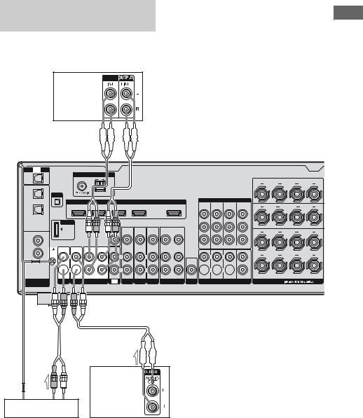
Connecting components with analog audio jacks
The following illustration shows how to connect a component which has analog jacks such as tape deck, etc.
MD deck, |
INPUT |
|
|
Tape deck |
|


 A
A
TV
OPTICAL
IN
OPTICAL
VIDEO 1
IN
SAT
IN
COAXIAL
DVD
IN
SA-CD/
CD
IN
DIGITAL
ASSIGNABLE
ANTENNA
FM AM
XM
HDMI
SAT IN |
BD IN |
DVD IN |
VIDEO 1 IN |
OUT |
DMPORT
DC5V 0.7A MAX
IN IN
SIGNAL
GND  L
L
 R
R 
 MONITOR
|
|
VIDEO |
VIDEO |
VIDEO |
VIDEO |
VIDEO |
VIDEO |
|
|
OUT |
IN |
IN |
IN |
OUT |
IN |
|
|
|
AUDIO |
AUDIO |
AUDIO |
AUDIO |
AUDIO |
OUT |
IN |
IN |
IN |
IN |
IN |
OUT |
IN |
|
L |
|
L |
L |
|
|
L |
|
R |
|
R |
R |
|
|
R |
PHONO SA-CD/CD MD/TAPE TV SAT DVD BD |
VIDEO 1 |
COMPONENT VIDEO
MONITOR |
COMPO 3 |
COMPO 2 |
COMPO 1 |
OUT |
IN |
IN |
IN |
|
|
|
Y |
|
|
|
PB/ |
|
|
|
CB |
|
|
|
PR/ |
|
|
|
CR |
|
ASSIGNABLE (INPUT ONLY) |
||
L |
|
L |
|
AUDIO |
|
|
|
OUT |
|
|
CENTER |
 R
R  R
R 
FRONT SURROUND SUR BACK SUBWOOFER
SUBWOOFER MULTI CHANNEL INPUT
SURROUND BACK
R L
SURROUND
R L
FRONT B
R L
FRONT A
R L
SPEAKERS

 A
A
|
A |
|
Super Audio |
|
CD player, |
Turntable |
CD player |
AAudio cord (not supplied)
Notes
•If your turntable has a ground (earth) wire, connect it to the U SIGNAL GND terminal.
•Before connecting cords, make sure to disconnect the AC power cord (mains lead).
Started Getting
23US
4b: Connecting the video components
How to connect your components
This section describes how to connect your video components to this receiver. Before you begin, refer to “Component to be connected” below for the pages which describe how to connect each component.
After connecting all your components, proceed to “5: Connecting the antennas (aerials)” (page 34).
Component to be connected Page
TV |
18 |
|
|
With HDMI jack |
25 |
|
|
DVD player |
27 |
|
|
Blu-ray disc player |
28 |
|
|
Satellite tuner, Set-top box |
29 |
|
|
DVD recorder, VCR |
30 |
|
|
Camcorder, video game, etc. |
30 |
|
|
Video input/output jack to be connected
The image quality depends on the connecting jack. Refer to the illustration that follows. Select the connection according to the jacks on your components.
COMPONENT VIDEO
Y
PB/
CB
PR/
CR
Digital Analog
High quality image
Note
Be sure to turn on the receiver when the video and audio of a playback component are being output to a TV via the receiver. If the power supply of the receiver is not turned on, neither video nor audio is transmitted.
Converting video signals
This receiver is equipped with a function for up-converting video signals. For details, see page 31.
24US
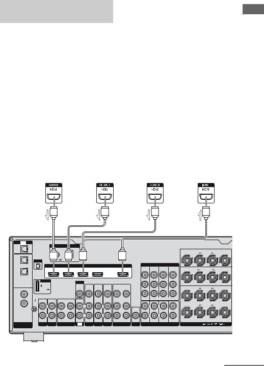
Connecting components with HDMI jacks
HDMI is the abbreviated name for HighDefinition Multimedia Interface. It is an interface which transmits video and audio signals in digital format.
HDMI features
•A digital audio signals transmitted by HDMI can be output from the speakers connected to the receiver. This signal supports Dolby Digital, DTS, and linear PCM.
•The receiver can receive Multi Linear PCM (up to 8 channels) with a sampling frequency of 192 kHz or less with an HDMI connection.
•Analog video signals input to the VIDEO jack or COMPONENT VIDEO jacks can be up-converted as HDMI signals. Audio signals are not output from an HDMI OUT jack when the image is converted.
•This receiver supports High Bitrate Audio (DTS-HD Master Audio, Dolby TrueHD), Deep Color and xvYCC transmission, extended by HDMI ver1.3.
•This receiver supports the Control for HDMI function (page 72).
Satellite tuner, |
|
Blu-ray disc player |
|
DVD player |
|
TV, projector, etc. |
||||
Set-top box |
|
|
|
|||||||
|
|
|
|
|
|
|
|
|
||
|
|
|
|
|
|
|
|
|
|
|
Audio/video |
|
Audio/video |
|
Audio/video |
|
Audio/video |
||||
signals |
|
signals |
|
signals |
|
signals |
||||
|
|
|
|
|
|
|
|
|
|
|
|
|
|
|
|
|
|
|
|
|
|
|
|
|
|
|
|
|
|
|
|
|
Started Getting
|
A |
|
|
|
|
A |
|
|
|
|
A |
|
|
|
|
|
A |
|
TV |
|
|
|
|
|
|
|
|
|
|
|
|
|
|
|
|
|
|
OPTICAL |
|
|
ANTENNA |
|
|
|
|
|
|
|
|
|
|
|
|
|
|
|
IN |
|
|
|
|
|
|
|
|
|
|
|
|
|
|
|
|
||
|
FM |
|
AM |
|
|
|
|
|
|
|
|
|
|
|
|
SURROUND BACK |
||
|
|
|
|
|
|
|
|
|
|
|
|
|
|
|
|
|
||
OPTICAL |
|
|
|
|
|
|
|
|
|
|
|
|
|
|
|
R |
|
L |
|
|
|
|
|
|
|
|
|
|
|
|
|
|
|
|
|
|
|
VIDEO 1 |
XM |
|
|
|
|
|
|
|
|
|
|
|
|
|
|
|
|
|
IN |
|
|
|
|
|
|
|
|
|
|
|
|
|
|
|
|
|
|
|
|
|
|
|
HDMI |
|
|
|
|
|
|
COMPONENT VIDEO |
|
|
|
|||
|
|
|
|
|
|
|
|
|
|
|
MONITOR |
COMPO 3 |
COMPO 2 |
COMPO 1 |
|
SURROUND |
|
|
|
|
SAT IN |
BD IN |
DVD IN |
VIDEO 1 IN |
|
OUT |
|
|
|
||||||||
SAT |
|
|
|
OUT |
IN |
IN |
IN |
R |
|
L |
||||||||
IN |
|
|
|
|
|
|
|
|
|
|
|
|
|
|
Y |
|
||
|
|
|
|
|
|
|
|
|
|
|
|
|
|
|
|
|
|
|
|
DMPORT |
|
|
MONITOR |
|
|
|
|
|
|
|
|
|
|
|
|
|
|
|
|
|
|
|
|
|
|
|
|
|
|
|
|
PB/ |
|
|
|
|
|
|
|
|
|
VIDEO |
VIDEO |
VIDEO |
VIDEO |
VIDEO |
VIDEO |
|
|
|
|
CB |
|
FRONT B |
|
|
|
|
|
|
|
|
|
|
|
R |
L |
|||||||
COAXIAL |
DC5V |
|
|
OUT |
IN |
IN |
IN |
OUT |
IN |
|
|
|
|
|
|
|||
DVD |
0.7A MAX |
|
|
|
|
|
|
|
|
|
|
|
|
PR/ |
|
|
|
|
|
|
|
|
|
|
|
|
|
|
|
|
|
|
|
|
|
||
IN |
|
|
|
|
|
|
|
|
|
|
|
|
|
|
CR |
|
|
|
|
|
|
|
|
|
AUDIO |
AUDIO |
AUDIO |
AUDIO |
AUDIO |
|
|
ASSIGNABLE (INPUT ONLY) |
|
|
|
||
SA-CD/ |
IN |
IN |
OUT |
IN |
IN |
IN |
IN |
IN |
OUT |
IN |
|
|
|
|
|
|
|
|
CD |
SIGNAL |
L |
|
L |
L |
|
|
L |
|
L |
|
|
L |
L |
|
|
FRONT A |
|
IN |
GND |
|
|
|
|
AUDIO |
|
|
R |
|
L |
|||||||
|
|
|
|
|
|
|
|
|
|
|
|
|
|
|
|
|||
|
|
|
|
|
|
|
|
|
|
|
OUT |
|
|
|
CENTER |
|
|
|
|
|
R |
|
R |
R |
|
|
R |
|
R |
|
|
R |
R |
|
|
|
|
|
|
|
|
|
|
|
|
|
|
|
|
FRONT |
SURROUND SUR BACK |
SUBWOOFER |
|
|
|
|
DIGITAL |
PHONO SA-CD/CD |
MD/TAPE |
TV |
SAT |
DVD |
BD |
VIDEO 1 |
SUBWOOFER |
MULTI CHANNEL INPUT |
SPEAKERS |
|
|||||||
ASSIGNABLE |
|
|
|
|
|
|
|
|
|
|
|
|
|
|
|
|
|
|
AHDMI cable (not supplied)
We recommend that you use a Sony HDMI cable.
continued
25US
Notes on connecting cables
•We recommend that you use a Sony HDMI cable.
•We recommend that you use an HDMI cable with the HDMI logo (made by Sony) for the HDMI jack corresponding to high speed (an HDMI version1.3a, category 2 cable) when you view images or listen to sound during a Deep Color transmission or when you watch a video image of 1080p or higher.
•We do not recommend using an HDMI-DVI conversion cable. When you connect an HDMI-DVI conversion cable to a DVI-D component, the sound and/or the image may not be output. Connect other audio cords or digital connecting cords, then set “Input Assign” in the Input Option menu when the sound is not output correctly.
•Before connecting cables, make sure to disconnect the AC power cord (mains lead).
Notes on HDMI connections
•An audio signal input to the HDMI IN jack is output from the SPEAKERS jacks and HDMI OUT jack. It is not output from any other audio jacks.
•Video signals input to the HDMI IN jack can only be output from the HDMI OUT jack. The video input signals cannot be output from the VIDEO OUT jacks or MONITOR OUT jacks.
•The audio and video signals of HDMI input are not output from the HDMI OUT jack while the receiver menu is displayed.
•When you want to listen to the sound from the TV speaker, set “Audio Out” to “TV+AMP” in the HDMI settings menu (page 49). If you cannot play back multi channel audio source, set to “AMP”. However, the sound will not output from the TV speaker.
•DSD signals of Super Audio CD are not input and output.
•Be sure to turn on the receiver when the video and audio of a playback component are being output to a TV via the receiver. If the power supply of the receiver is not turned on, neither video nor audio is transmitted.
•Audio signals (sampling frequency, bit length, etc.) transmitted from a HDMI jack may be suppressed by the connected component. Check the setup of the connected component if the image is poor or the sound does not come out of a component connected via the HDMI cable.
•Sound may be interrupted when the sampling frequency, the number of channels or audio format of audio output signals from the playback component is switched.
•When the connected component is not compatible with copyright protection technology (HDCP), the image and/or the sound from the HDMI OUT jack may be distorted or may not be output.
In this case, check the specification of the connected component.
•You can enjoy High Bitrate Audio (DTS-HD Master Audio, Dolby TrueHD), multi channel Linear PCM only with an HDMI connection.
•Set the image resolution of the playback component to more than 720p to enjoy High Bitrate Audio (DTS-HD Master Audio, Dolby TrueHD).
•The image resolution of playback component may need certain settings be made before you can enjoy multi channel Linear PCM. Refer to the operating instructions of the playback component.
•Not every HDMI component supports all functions that are defined by the specified HDMI version. For example, components that support HDMI, ver. 1.3a, may not support Deep Color.
•Refer to the operating instructions of each connected component for details.
26US
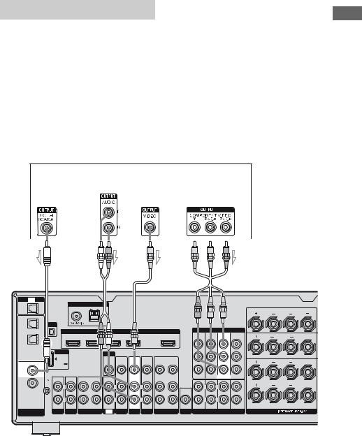
Connecting a DVD player
The following illustration shows how to connect a DVD player.
It is not necessary to connect all the cords. Connect audio and video cords according to the jacks of your components.
Notes
•To input multi channel digital audio from the DVD player, set the digital audio output setting on the DVD player. Refer to the operating instructions supplied with the DVD player.
•Before connecting cords, make sure to disconnect the AC power cord (mains lead).
Tips
•All the digital audio jacks are compatible with 32 kHz, 44.1 kHz, 48 kHz, and 96 kHz sampling frequencies.
•The COMPONENT VIDEO COMPO 2 IN jacks have been assigned to the DVD player. If you connect your DVD player to the COMPONENT VIDEO COMPO 1 or COMPO 3 IN jacks, set “Input Assign” in the Input menu (page 82).
DVD player
Audio signals |
Video signals |
|||||||||||||
|
|
|
|
|
|
|
|
|
|
|
|
|
|
|
|
|
|
|
|
|
|
|
|
|
|
|
|
|
|
|
|
|
|
|
|
|
|
|
|
|
|
|
|
|
|
|
|
|
|
|
|
|
|
|
|
|
|
|
|
|
|
|
|
|
|
|
|
|
|
|
|
|
|
|
|
|
|
|
|
|
|
|
|
|
|
|
|
|
|
|
|
|
|
|
|
|
|
|
|
|
|
|
|
|
Started Getting
|
A |
|
|
|
B |
|
|
C |
|
|
|
D |
|
|
||
|
TV |
|
|
|
|
|
|
|
|
|
|
|
|
|
|
|
OPTICAL |
|
|
ANTENNA |
|
|
|
|
|
|
|
|
|
|
|
|
|
IN |
|
|
|
|
|
|
|
|
|
|
|
|
|
|
||
|
|
FM |
AM |
|
|
|
|
|
|
|
|
|
|
SURROUND BACK |
|
|
|
|
|
|
|
|
|
|
|
|
|
|
|
|
|
|
|
OPTICAL |
|
|
|
|
|
|
|
|
|
|
|
|
|
R |
|
L |
|
|
|
|
|
|
|
|
|
|
|
|
|
|
|
|
|
VIDEO 1 |
XM |
|
|
|
|
|
|
|
|
|
|
|
|
|
|
|
IN |
|
|
|
|
|
|
|
|
|
|
|
|
|
|
|
|
|
|
|
|
|
HDMI |
|
|
|
|
|
COMPONENT VIDEO |
|
|
|||
|
|
|
|
|
|
|
|
|
|
MONITOR |
COMPO 3 |
COMPO 2 |
COMPO 1 |
SURROUND |
|
|
|
|
|
SAT IN |
BD IN |
DVD IN |
VIDEO 1 IN |
|
OUT |
|
|||||||
SAT |
|
|
|
OUT |
IN |
IN |
IN |
|
|
|||||||
|
|
|
|
|
|
|
|
|
|
|
|
|
R |
|
L |
|
IN |
|
|
|
|
|
|
|
|
|
|
|
|
|
|
||
|
|
|
|
|
|
|
|
|
|
|
|
|
|
Y |
|
|
|
DMPORT |
|
|
MONITOR |
|
|
|
|
|
|
|
|
|
|
|
|
|
|
|
|
|
|
|
|
|
|
|
|
|
PB/ |
|
|
|
|
|
|
|
|
VIDEO |
VIDEO |
VIDEO |
VIDEO |
VIDEO |
VIDEO |
|
|
|
CB |
FRONT B |
|
|
|
|
|
|
|
|
|
R |
L |
|||||||
COAXIAL |
DC5V |
|
|
OUT |
IN |
IN |
IN |
OUT |
IN |
|
|
|
|
|||
DVD |
0.7A MAX |
|
|
|
|
|
|
|
|
|
|
|
PR/ |
|
|
|
IN |
|
|
|
|
|
|
|
|
|
|
|
|
|
CR |
|
|
|
|
|
|
|
|
AUDIO |
AUDIO |
AUDIO |
AUDIO |
AUDIO |
|
ASSIGNABLE (INPUT ONLY) |
|
|
||
SA-CD/ |
IN |
IN |
OUT |
IN |
IN |
IN |
IN |
IN |
OUT |
IN |
|
|
|
|
|
|
CD |
SIGNAL |
L |
|
L |
L |
|
|
L |
|
L |
|
L |
L |
|
FRONT A |
|
IN |
GND |
|
|
|
|
AUDIO |
R |
|
L |
|||||||
|
|
|
|
|
|
|
|
|
|
|
|
|
|
|||
|
|
|
|
|
|
|
|
|
|
|
OUT |
|
|
CENTER |
|
|
|
|
R |
|
R |
R |
|
|
R |
|
R |
|
R |
R |
|
|
|
|
|
|
|
|
|
|
|
|
|
|
FRONT |
SURROUND SUR BACK |
SUBWOOFER |
|
|
|
DIGITAL |
PHONO SA-CD/CD MD/TAPE TV SAT DVD BD |
VIDEO 1 SUBWOOFER |
MULTI CHANNEL INPUT |
SPEAKERS |
ASSIGNABLE |
|
|
|
|
ACoaxial digital cord (not supplied)
BAudio cord (not supplied)
CVideo cord (not supplied)
DComponent video cord (not supplied)
27US

Connecting a Blu-ray disc player
The following illustration shows how to connect a Blu-ray disc player.
It is not necessary to connect all the cords. Connect audio and video cords according to the jacks of your components.
Notes
•To input multi channel digital audio from the Bluray disc player, set the digital audio output setting on the Blu-ray disc player. Refer to the operating instructions supplied with the Blu-ray disc player.
•Before connecting cords, make sure to disconnect the AC power cord (mains lead).
Blu-ray disc player
Audio signals |
Video signals |
||||||
|
|
|
|
|
|
|
|
|
|
|
|
|
|
|
|
|
|
|
|
|
|
|
|
|
|
|
|
|
|
|
|
|
|
|
|
|
|
|
|
|
|
|
|
|
|
|
|
|
|
|
|
|
|
|
|

 A
A  B
B 

 C
C
TV
OPTICAL
IN
OPTICAL
VIDEO 1
IN
SAT
IN
COAXIAL
DVD
IN
SA-CD/
CD
IN
DIGITAL
ASSIGNABLE
XM
DMPORT
DC5V 0.7A MAX
ANTENNA
FM AM
HDMI

SAT IN BD IN DVD IN VIDEO 1 IN OUT
MONITOR
VIDEO |
VIDEO |
VIDEO |
VIDEO |
VIDEO |
VIDEO |
OUT |
IN |
IN |
IN |
OUT |
IN |
COMPONENT VIDEO
MONITOR |
COMPO 3 |
COMPO 2 |
COMPO 1 |
OUT |
IN |
IN |
IN |
Y
PB/
CB
PR/
CR
|
|
|
|
|
AUDIO |
AUDIO |
AUDIO |
AUDIO |
AUDIO |
|
ASSIGNABLE (INPUT ONLY) |
IN |
IN |
OUT |
IN |
IN |
IN |
IN |
IN |
OUT |
IN |
|
|
SIGNAL |
|
|
|
|
|
|
|
|
|
|
|
GND |
L |
|
L |
|
L |
|
L |
|
L |
L |
L |
|
|
|
|
|
|||||||
|
|
|
|
|
|
|
|
|
AUDIO |
|
|
|
|
|
|
|
|
|
|
|
OUT |
|
CENTER |
|
R |
|
R |
|
R |
|
R |
|
R |
R |
R |
|
|
|
|
|
|
|
|
|
|
FRONT SURROUND SUR BACK SUBWOOFER |
|
PHONO SA-CD/CD |
MD/TAPE |
TV |
SAT |
DVD |
BD |
VIDEO 1 SUBWOOFER |
MULTI CHANNEL INPUT |
||||
SURROUND BACK
R L
SURROUND
R L
FRONT B
R L
FRONT A
R L
SPEAKERS
AAudio cord (not supplied) BVideo cord (not supplied)
CComponent video cord (not supplied)
Tip
The COMPONENT VIDEO COMPO 1 IN jacks have been assigned to the Blu-ray disc player. If you connect your Blu-ray disc player to the COMPONENT VIDEO COMPO 2 or COMPO 3 IN jacks, set “Input Assign” in the Input menu (page 82).
28US
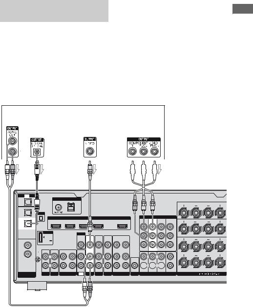
Connecting a satellite tuner, set-top box
The following illustration shows how to connect a satellite tuner or set-top box.
It is not necessary to connect all the cords. Connect audio and video cords according to the jacks of your components.
Notes
•Before connecting cords, make sure to disconnect the AC power cord (mains lead).
•When connecting optical digital cords, insert the plugs straight in until they click into place.
•Do not bend or tie optical digital cords.
Tips
•All the digital audio jacks are compatible with 32 kHz, 44.1 kHz, 48 kHz, and 96 kHz sampling frequencies.
•The COMPONENT VIDEO COMPO 3 IN jacks have been assigned to the satellite tuner. If you connect your satellite tuner to the COMPONENT VIDEO COMPO 1 or COMPO 2 IN jacks, set “Input Assign” in the Input menu (page 82).
Satellite tuner, Set-top box
Audio signals |
Video signals |
|||||||||
|
|
|
|
|
|
|
|
|
|
|
|
|
|
|
|
|
|
|
|
|
|
|
|
|
|
|
|
|
|
|
|
|
|
|
|
|
|
|
|
|
|
|
|
|
|
|
|
|
|
|
|
|
|
|
|
|
|
|
|
|
|
|
|
|
|
|
|
|
|
|
|
|
|
|
|
|
|
|
|
|
|
|
|
|
|
|
|
|
|
|
|
|
|
|
|
|
|
|
Started Getting
A |
|
B |
|
|
|
|
C |
|
|
|
TV |
|
|
|
|
|
|
|
|
|
|
OPTICAL |
|
|
ANTENNA |
|
|
|
|
|
|
|
IN |
|
|
|
|
|
|
|
|
||
|
|
FM |
AM |
|
|
|
|
|
|
|
OPTICAL |
|
|
|
|
|
|
|
|
|
|
VIDEO 1 |
XM |
|
|
|
|
|
|
|
|
|
IN |
|
|
|
|
|
|
|
|
|
|
|
|
|
|
|
HDMI |
|
|
|
|
|
SAT |
|
|
SAT IN |
BD IN |
DVD IN |
VIDEO 1 IN |
|
OUT |
||
|
|
|
|
|
|
|
|
|
|
|
IN |
|
|
|
|
|
|
|
|
|
|
|
DMPORT |
|
|
MONITOR |
|
|
|
|
||
|
|
|
|
|
|
|
|
|
||
|
|
|
|
|
VIDEO |
VIDEO |
VIDEO |
VIDEO |
VIDEO |
VIDEO |
COAXIAL |
DC5V |
|
|
OUT |
IN |
IN |
IN |
OUT |
IN |
|
DVD |
0.7A MAX |
|
|
|
|
|
|
|
|
|
|
|
|
|
|
|
|
|
|
|
|
IN |
|
|
|
|
|
|
|
|
|
|
|
|
|
|
|
|
AUDIO |
AUDIO |
AUDIO |
AUDIO |
AUDIO |
SA-CD/ |
IN |
IN |
OUT |
IN |
IN |
IN |
IN |
IN |
OUT |
IN |
CD |
SIGNAL |
|
|
|
|
|
|
|
|
|
IN |
GND |
L |
|
L |
|
L |
|
L |
|
L |
|
|
R |
|
R |
|
R |
|
R |
|
R |


 D
D
COMPONENT VIDEO
MONITOR |
COMPO 3 |
COMPO 2 |
COMPO 1 |
OUT |
IN |
IN |
IN |
|
|
|
Y |
|
|
|
PB/ |
|
|
|
CB |
|
|
|
PR/ |
|
|
|
CR |
|
ASSIGNABLE (INPUT ONLY) |
||
L |
|
L |
|
AUDIO |
|
|
|
OUT |
|
|
CENTER |
 R
R  R
R 
FRONT SURROUND SUR BACK SUBWOOFER
DIGITAL |
PHONO SA-CD/CD MD/TAPE TV SAT DVD BD |
VIDEO 1 SUBWOOFER |
MULTI CHANNEL INPUT |
ASSIGNABLE |
|
|
|
SURROUND BACK
R L
SURROUND
R L
FRONT B
R L
FRONT A
R L
SPEAKERS
AAudio cord (not supplied)
BOptical digital cord (not supplied) CVideo cord (not supplied)
DComponent video cord (not supplied)
29US
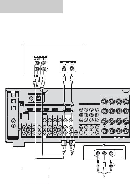
Connecting components with analog video and audio jack
The following illustration shows how to connect a component which has analog jacks such as a DVD recorder, VCR, etc.
It is not necessary to connect all the cords. Connect audio and video cords according to the jacks of your components.
Notes
•Before connecting cords, make sure to disconnect the AC power cord (mains lead)
•Be sure to change the factory setting of the VIDEO 1 input button on the remote so that you can use the button to control your DVD recorder. For details, see “Programming the remote” (page 99).
•You can also rename the VIDEO 1 input so that it can be displayed on the TV screen and display. For details, see “Naming inputs” (page 81).
DVD recorder, VCR
Audio signals |
Video signals |
|||||||
|
|
|
|
|
|
|
|
|
|
|
|
|
|
|
|
|
|
|
|
|
|
|
|
|
|
|
|
|
|
|
|
|
|
|
|
|
|
|
|
|
|
|
|
|
|
|
|
|
|
|
|
|
|
|
|
|
|
|
|
|
|
|
A 

 B
B
TV
OPTICAL
IN
OPTICAL
VIDEO 1
IN
SAT
IN
COAXIAL
DVD
IN
SA-CD/
CD
IN
DIGITAL
ASSIGNABLE
ANTENNA
FM AM
XM
HDMI
SAT IN |
BD IN |
DVD IN |
VIDEO 1 IN |
OUT |
DMPORT
DC5V 0.7A MAX
IN |
IN |
OUT |
IN |
SIGNAL |
|
|
|
GND |
L |
|
L |
|
|
||
|
R |
|
R |
MONITOR
VIDEO |
VIDEO |
VIDEO |
VIDEO |
VIDEO |
VIDEO |
OUT |
IN |
IN |
IN |
OUT |
IN |
|
AUDIO |
AUDIO |
AUDIO |
AUDIO |
AUDIO |
IN |
IN |
IN |
IN |
OUT |
IN |
|
L |
L |
|
|
L |
|
R |
R |
|
|
R |
PHONO SA-CD/CD MD/TAPE TV SAT DVD BD |
VIDEO 1 |
COMPONENT VIDEO
MONITOR |
COMPO 3 |
COMPO 2 |
COMPO 1 |
OUT |
IN |
IN |
IN |
|
|
|
Y |
|
|
|
PB/ |
|
|
|
CB |
|
|
|
PR/ |
|
|
|
CR |
|
ASSIGNABLE (INPUT ONLY) |
||
L |
|
L |
|
AUDIO |
|
|
|
OUT |
|
|
CENTER |
 R
R  R
R 
FRONT SURROUND SUR BACK SUBWOOFER
SUBWOOFER MULTI CHANNEL INPUT
SURROUND BACK
R L
SURROUND
R L
FRONT B
R L
FRONT A
R L
SPEAKERS
VIDEO 2 IN/PORTABLE AV IN
VIDEO |
L AUDIO R |
To the VIDEO 2 IN/PORTABLE AV IN jacks (Front panel)
Camcorder,
video game
C
AAudio cord (not supplied)
BVideo cord (not supplied)
CAudio/video cord (not supplied)
30US
 Loading...