

Page 1

3-859-657-31(2)
FM Stereo
\
FM-AM Receiver
Operating instructions
Mode d'emploi
___________
STR-DE515
STR-DE415
STR-DE315
STR-D360Z
© 1997 by Sony CojporaSon
Page 2

WARNING
To prevent fire or shock
hazard, do not expose
the unit to rain or
moisture.
To avoid electrical shock, do not open
the cabinet. Refer servicing to qualified
personnel only.
I
CAUTION
TO PREVENT ELECTRIC SHOCK, DO
NOT USE THIS POLARIZED AC PLUG
WITH AN EXTENSION CORD,
RECEPTACLE OR OTHER OUTLET
UNLESS THE BLADES CAN BE FULLY
INSERTED TO PREVENT BLADE
EXPOSURE.
Precautions
On safety
• should any solid object or liquid fall
into the cabinet, unplug the receiver
and have it checked by qualified
personnel before operating it any
further.
On power sources
• Before operating the receiver, check
that the operating voltage is identical
with your local power supply. The
operating voltage is indicated on the
nameplate at the rear of the receiver.
• The receiver is not disconnected from
the AC power source (MAINS) as
long as it is connected to the wall
outlet, even if the receiver itself has
been turned off.
• If you are not going to use the
receiver for a long time, be sure to
disconnect the receiver from the wall
outlet. To disconnect the AC power
cord, grasp the plug itself; never pull
the cord.
• One blade of the plug is wider than
the other for the purpose of safety
and will fit into the wall outlet only
one way. If you are unable to insert
the plug fully into the outlet, contact
your dealer.
• Should the AC power cord need to be
changed, have it done at a qualified
service shop only.
On placement
• Place the receiver in a location with
adequate ventilation to prevent heat
build'up and prolong the life of the
receiver.
• Do not place the receiver near heat
sources, or in a place subject to direct
sunlight, excessive dust or
mechanical shock.
• Do not place anything on top of the
cabinet that might block the
ventilation holes and cause
malfunctions.
On operation
• Before connecting other components,
be sure to turn off and unplug the
receiver.
On cleaning
• Qean the cabinet, panel and controls
with a soft cloth slightly moistened
with a mild detergent solution. Do
not use any type of abrasive pad,
scouring powder or solvent such as
alcohol or benzine.
If you have any question or problem
concerning your receiver, please
consult your nearest Sony dealer.
Page 3

About This Manual Table OF CONTENTS
The instructions in this manual arc for
modeU STR-DK15, STR-DE4153TRDE315 and STR-D360Z. Check your
model number by looking at the upper
right comer of the front panel or lower
right comer of the remote. In this
manual, the STR-DE515 is the model
used for illustration purposes, any
difference in operation is clearly
indicated in the text, for example,
"STR-DE515 only". \
Type of differences
'\^oiiel
Featur^\
MIX AUDIO
OUT
WOOFER
5.1/DVD
WIRELESS
REAR
SPEAKER
VIDEO
MONITOR
Conventions
The instructions in this manual describe
the controls on the receiver. You can
also use the controls on the remote if
they have the same or similar names as
those on the receiver.
• A "Quick Reference Guide" is
supplied on page 23.
• The "Remote Button Descriptions"
section on page 22 provides an
overview of the remote buttons.
• The following icons are used in this
manual:
^ making the task easier.
DE5150E415 DE31S D360Z
•
•
•
•
Indicates that you can use only
the remote to do the task.
Indicates hints and tips for
Getting Started
Unpacking 4
Hookup Overview 4
Antenna Hookups 5
Audio Component Hookups 5
Speaker System Hookups 6
Video Component Hookups 7
AC Hookups 8
Before You Use Your Receiver 8
Receiver Operations
Selecting a Component 8
Receiving Broadcasts 11
Presetting Radio Stations 12
Recording 13
Choosing a Surround Mode 14
Getting the Most Out of Dolby Pro Logic Surround Sound 15
Additional Information
Troubleshooting 17
Specifications 18
Glossary 19
Index 20
Rear Panel Descriptions 21
Remote Button Descriptions 22
Quick Reference Guide 23
This receiver has the Dolby Surround
system.
Manufactured under license from Dolby
Laboratories Licensing Corporation.
"Dolby'Tro Logic" and the double-D
symbol are trademarks of Dolby
Laboratories Licensing Corporation.
Page 4
Getting Started
Unpacking
Qieck that you received the following items with the
receiver:
• FM wire antenna (1)
• AM loop antenna (1)
• Remote controller (remote) (1)
• Size AA (R6) batteries (2)
Inserting batteries into the remote
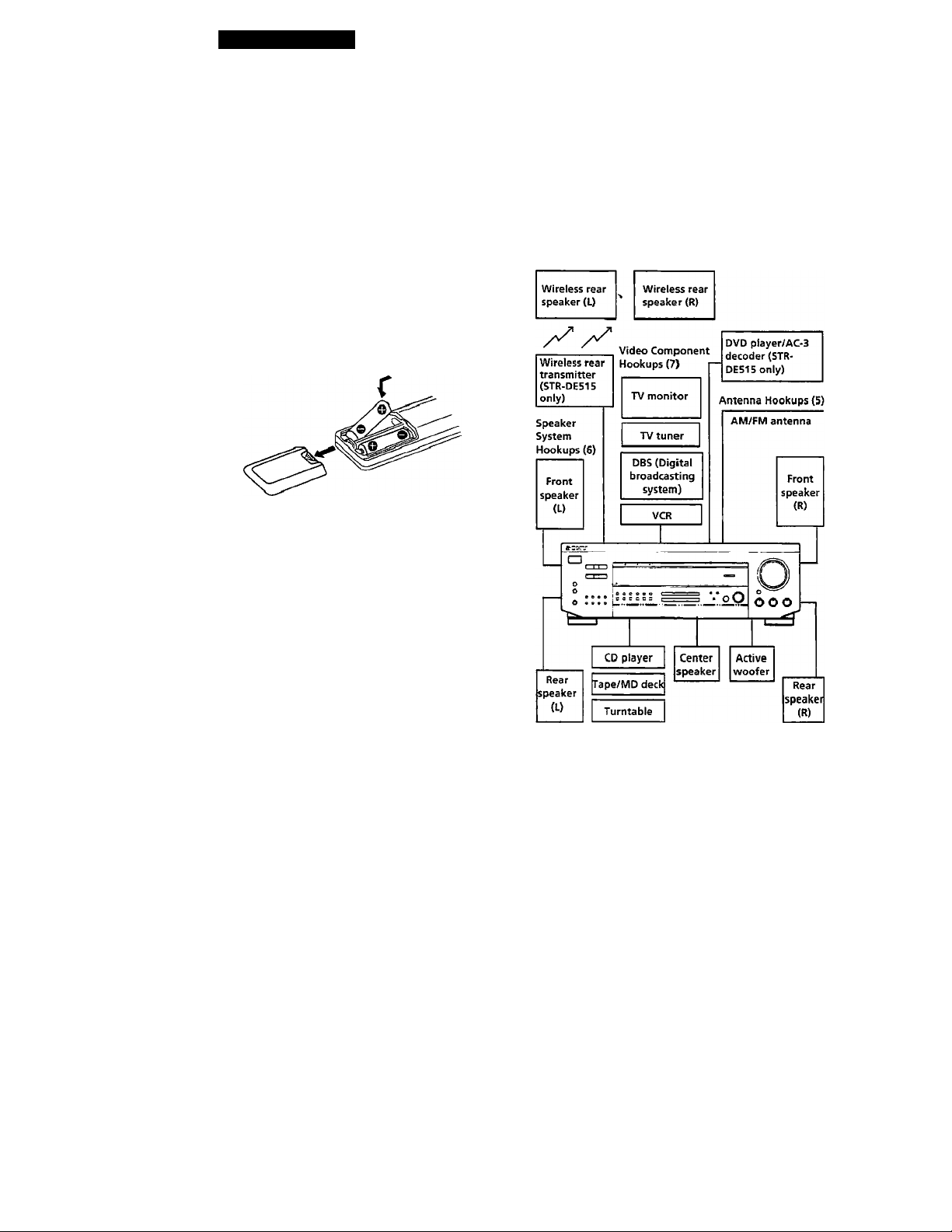
Insert two size AA (R6) batteries in accordance with
the + and - markings on the battery compartment.
When using the remote, point it at the remote sensor [
on the receiver.
'(j' When to replace batteries
Under normal use, the batteries should last for about 6
months. When the remote no longer operates the
receiver, replace both batteries with new ones.
Notes
• Do not leave the remote in an extremely hot or humid
place.
• Do not use a new battery with an.old one.
• Do not expose the remote sensor to direct sunlight or
lighting apparatuses. Doing so may cause a malfunction.
• If you don't use the remote for an extended period of time,
remove the batteries to avoid possible damage from
battery leakage and corrosion.
Hookup Overview
The receiver allows you to connect and control the
following audio/ video components. Follow the
hookup procedures for the components that you want
to connect to the receiver on the pages specified. To
leam the locations and names of each jack, see "Rear
Panel Descriptions" on page 21.
I
Audio Component
Hookups (5)
Before you get started
• Turn off the power to all components before making
any connections.
• Do not connect the AC power cords until all of the
cormections are completed.
• Be sure to make connections firmly to avoid hum
and noise.
• When connecting an audio/video cable, be sure to
match the color-coded pins to the appropriate jacks
on the components: Yellow (video) to Yellow; White
(left, audio) to White; and Red (right, audio) to Red.
HV
4'
Page 5
Getting Started
Antenna Hookups
Overview
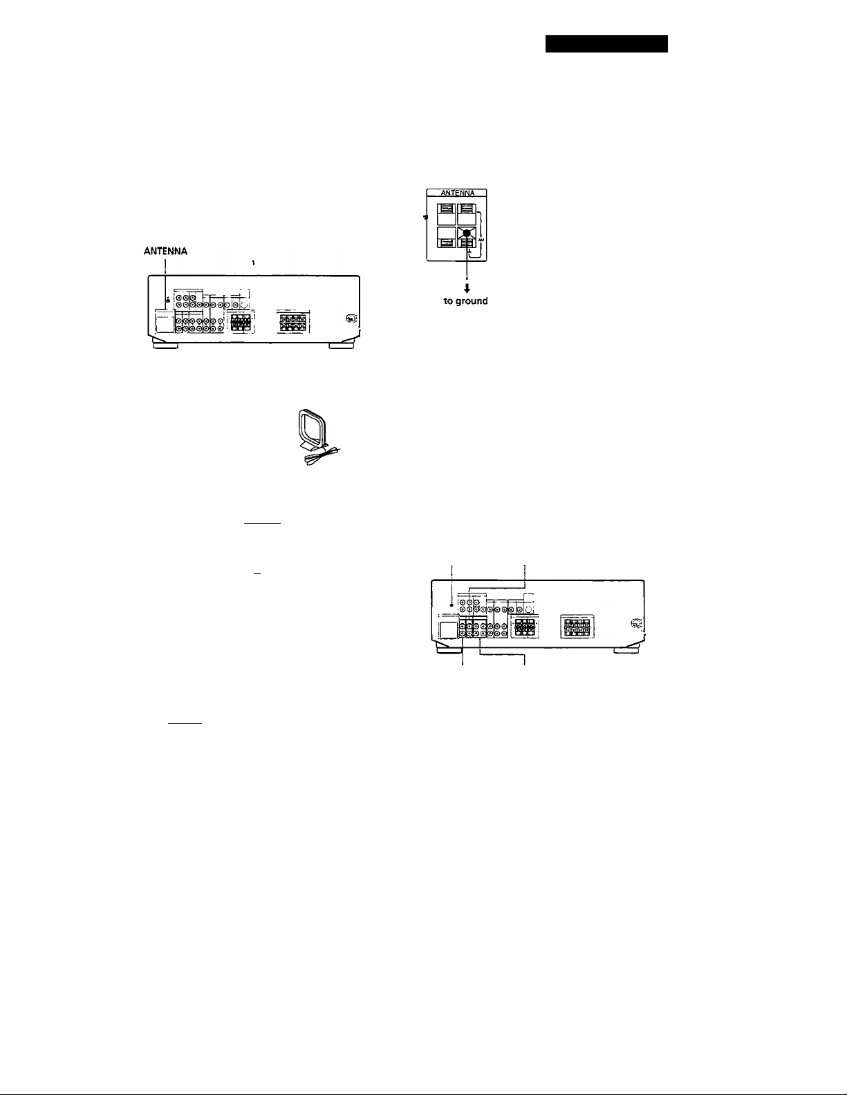
This section describes how to connect AM and FM
antennas to the receiver. If you want to receive radio
broadcasts with the receiver, complete these
connections first, then go to the following pages.
For specific locations of the terminals, see the
illustration below.
What antennas will I need?
• FM wire antenna
(supplied) (I)
Hookups
FM wire antenna
After connecting
the wire
antenna, keep it
as horizontal as
possible.
Receiver AM loop antenna
^itJ ^ II I I
u d
AM loop antenna
(supplied) (1)
ANTENNA
m
Connecting a ground wire
To prevent hum, connect a ground wire (not supplied)
to the ih ground terminal. If you've connected an
outdoor antenna, be sure to connect the ground for
lightning protection.
Receiver
Where do I go next?
If you want to connect other components, go on to the next
section, ¡/you're only planning to use the receiver to listm
to the radio, go to "Speaker System Hookups " on pages 6
and 7.
Audio Component Hookups
Overview
This section describes how to connect your audio
components to the receiver. If you want to use the
receiver as an amplifier, complete these connections.
For specific locations of the jacks, see the illustration
below.
-h CD
If you have poor FM reception
Connect a 75*ohm coaxial cable (not supplied) to an FM
outdoor antenna. Pull back the mesh portion
surrounding the inner cable and connect it to the earth
terminal (right side). Connect the inner cable to the FM
terminal (left side).
Receiver
amtenna"
Q If you have poor AM reception
Coiuiecl a 20 to 50 ft. (6 to 15-meter) insulated wire (not
supplied) to the AM antenna terminal in addition to the
AM loop antenna. Try to extend the wire outdoors and
keep it horizontal.
PHONO TAPE/MD
(Except STR-DE315)
What cords will I need?
Audio cords (not supplied) (1 for each CD player or
turntable; 2 for each tape deck or MD recorder)
White (L)
Red (R)
White (L)
Red(R)
(continued)
Page 6
Getting Started as
Hookups
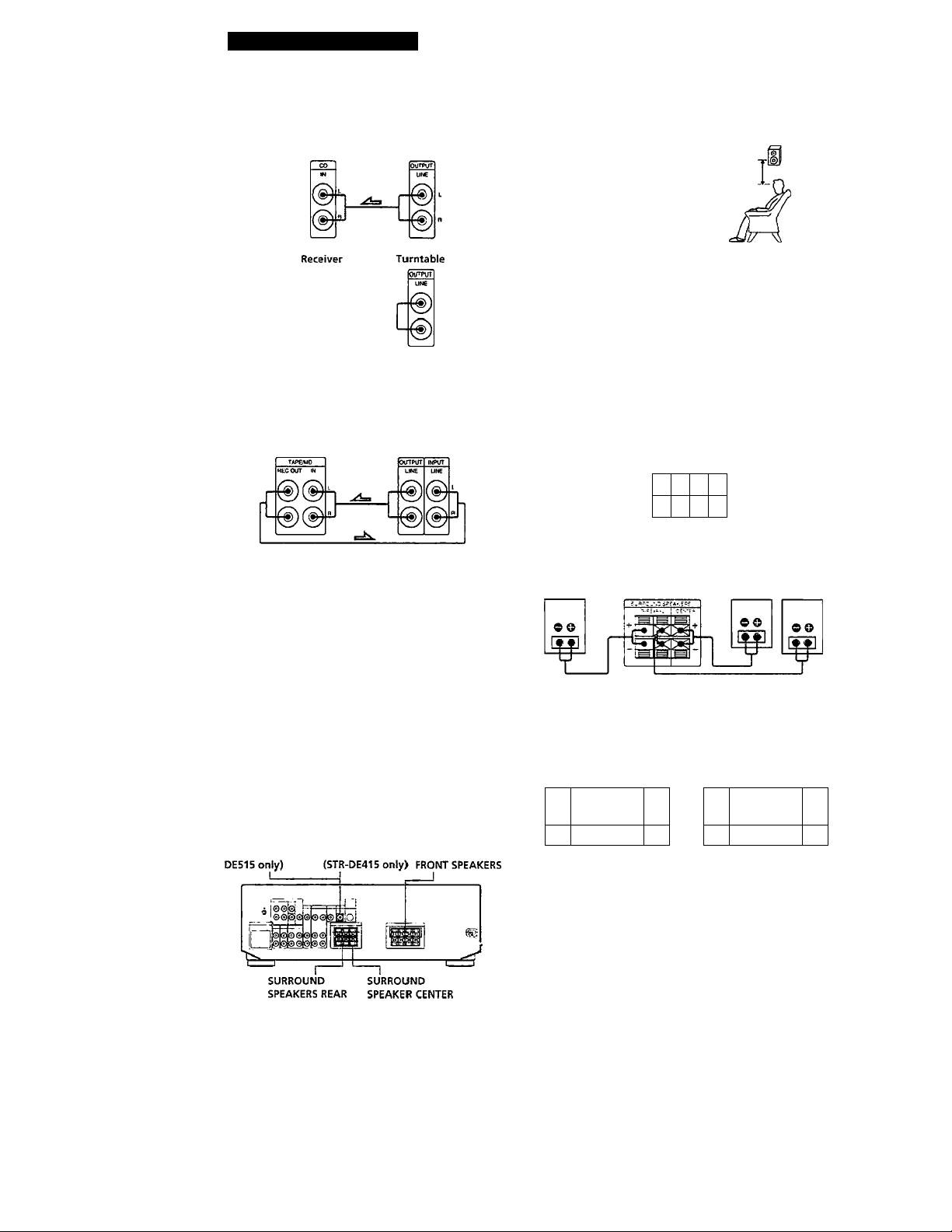
The arrow =
CD player
Turntable
(except
STR-DE315)
If your turntable has an earth lead
To prevent hum, connect the earth lead to the /h ground
terminal on the receiver.
Tape deck or MD recorder
a- indicates signal flow.
Receiver CD player
Receiver Tape deck or MD recorder
For optimum surround sound effect, place your speakers as shown below.
Rear speaker
45"
60 - 90 cm
e
What cords will I Tjeed?
Speaker cord {not supplied) (1 for each speaker)
(+)
(-) ^ ^ (-)
Twist the stripped ends of the cord about 2/3 mch (15 mm).
Be sure to match the speaker cord to the appropriate
terminal on the components: + to + and - to If the cords
are reversed, the sound will be distorted and will lack. bass.
Hookups
Front speakers
Front speaker
(R)
Receiver
raOWT &PEAKSBS
Front speaker
(L)
m
60
TmTMTsT
m
09
Where do I go next?
Go on to the next section to connect the speakers.
Speaker System Hookups
Overview
This section describes how to connect your speakers to
the receiver. Although front (left and right) speakers
are required, center and rear speakers are optional.
Adding center and rear speakers will enhance the
surround effects. Connecting an active woofer will
increase bass response (STR-DE515/DE415 only). For
specific locations of the terminals, see the illustration
below.
WOOFER (STR- MIX AUDIO OUT
Rear and center speakers
Rear speaker
(R) Receiver
Note (except STR-DE515)
Be sure to connect the both rear speakers (L and R).
.No sound is heard if only one speaker is connected.
Active woofer (STR-DE51S/DE415 only)
STR-DE515 STR-DE415
Receiver Active woofer Receiver Active woofer
ftOOfit
mpuT
Center speaker (U
WCOttT
=3^
Wireless rear Speaker (STR-DE515 only)
• When using an optional Sony Wireless Speaker System,
connect the transmitter to the WIRELESS REAR SPEAKER
connector.
Note
• Do not connect any other component.
Rear speaker
.=ix
• Wireless rear speaker does not function under stereo
mode, DOLBY (3CH LOGIC) and C. STTJDIO A/B (3CH
LOGIC) mode.
INPUT
Page 7
Getting Started
'Ç' If you have an additional front speaker system
Connect them to the FRONT SPEAKERS B terminals.
'Ç' If your TV monitor uses separate speakers
You can connect one of them to the SURROUND
SPEAKER CENTER terminals for use with Dolby Pro
Logic Surround sound (see page 15).
Selecting the speaker system
To drive the speakers, select the speaker system as
follows:
To drive
Speaker system A (connecLed
to the FRONT SPEAKERS A>
terminals)
Speaker system B (connected
to the FRONT SPEAKERS B
terminals)
Both speaker systems A and
B (series connection)
Notes
• If you want to enjoy the surround sound, be sure to
connect the front speakers to the FRONT SPEAKERS A
terminal.
• No sound is heard when you press SPEAKERS A+B
without connecting speaker system B.
Depress SPEAKERS button
A
B
A+B
Where do I go next?
To complete your system, go to "AC Hookups" on page 8. If
you want to connect video components to enjoy surround
sound when watching/listening to TV programs or video
tapes, go on to the next section.
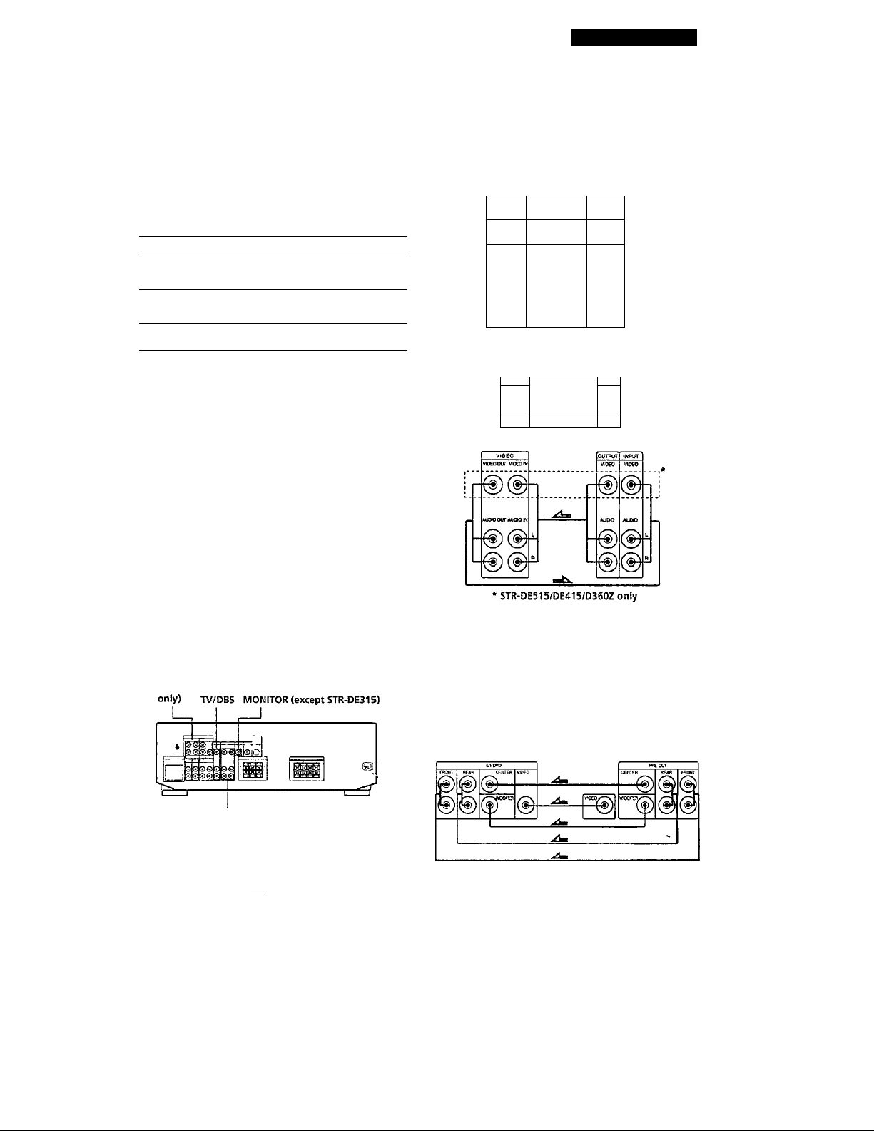
. Video cable (not supplied) (1 for a TV monitor)
Yellow =C^i»
----------------------
™G>= Yellow
Hookups ~ • ■
The arrow indicates signal flow.
TV/DBS TV tuner or Digital
MONITOR (except STR-DE315)
VCR
Receiver broadcasting system
Tv.oas
vioeoM
- ¡-
0-
KUDO IN
L
0^
J L
0-
• STR-DE515/DE415/D350Z only
Receiver
MONITOA
VIDEO Otr
Receiver
outwT
VIDEO
■0
AUOIO
-0^
■0»
TV monitor
mpuT
VIDEO
VCR
Video Component Hookups
Overview
This section describes how to connect video
components to the receiver. For specific locations of the
jacks, see the illustration below.
5.1/DVD
(STR-DE515
VIDEO
What cables will I need?
• Audio/video cable (not supplied) (1 for each TV tuner or
Digital broadcasting system; 2 for the VCR)
Yellow >naQ3a Yellow
White (L) y ^ aiBig>. White (L)
Red(R) Oar»/ \j<I> Red(R)
DVD player/AC-3 decoder (STR-DE515 only)
You can play decoded Dolby Digital AC-3 soundtracks through the speakers connected to the amplifier.
If you have a Dolby Digital AC-3 decoder you can
amplify a decoded Dolby Digital AC-3 soundtrack with
the following connections.
Dolby Digital AC-3
Receiver
decoder (etc.)
Page 8
Getting Started
Where do / go next?
Go on to the next section to connect the AC power cord and
complete your twme theater system.
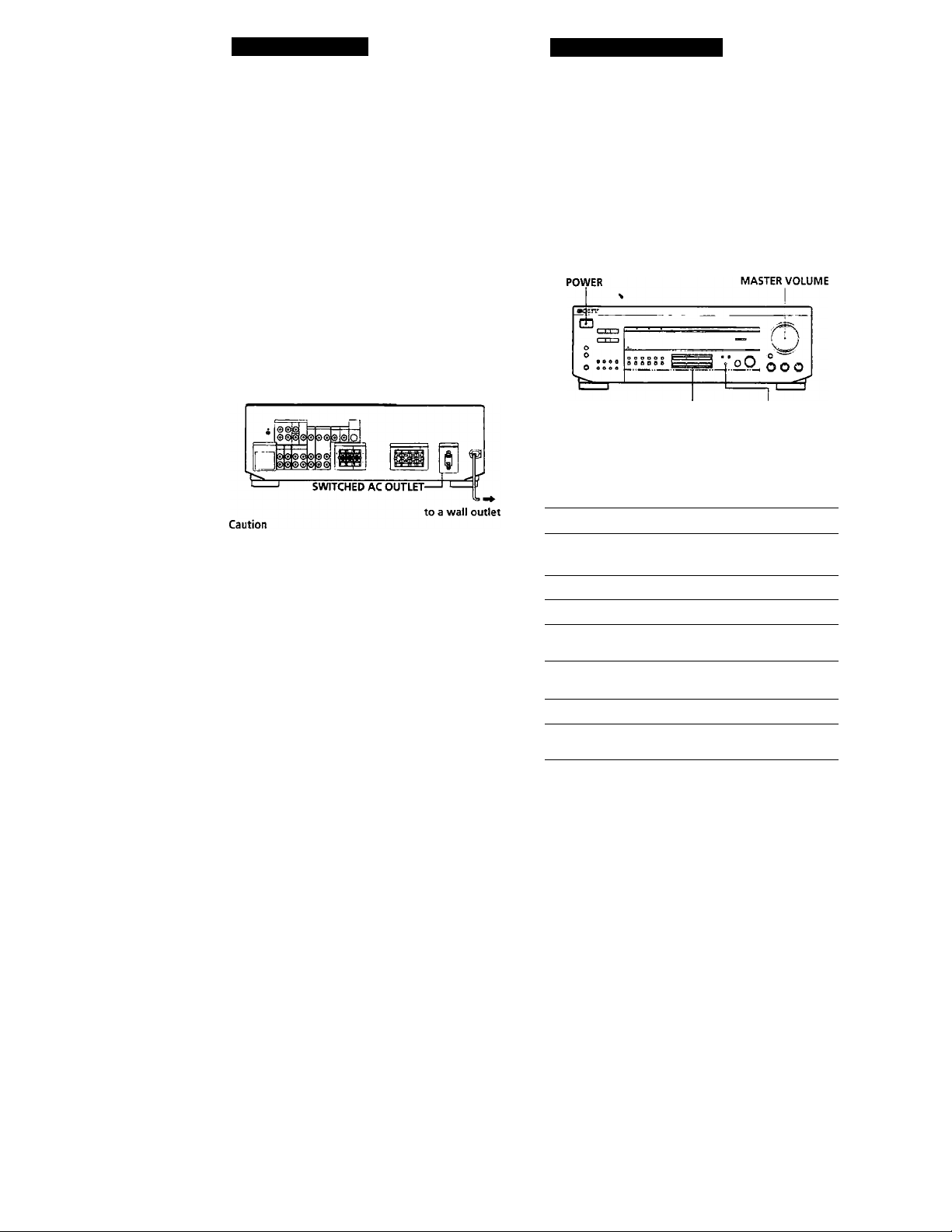
AC Hookups
Connecting the AC power cord
Connect the AC power cord from this receiver and
from your audio/video components to a wall outlet.
If you cormect other audio components to the
SWITCHED AC OUTLET on the receiver, the receiver
can supply power to the connected components so you
can turn on/off the whole system when you turn on/
off the receiver.
Receiver operations
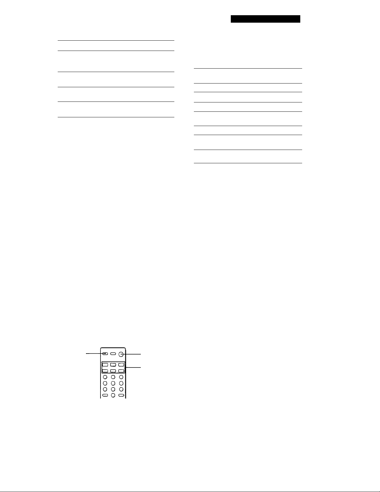
Selecting a Component
To listen to or watch a cormected component, first
select the function on the receiver or with the remote.
Before you begin, make sure you have:
• Connected all components securely and correctly as
indicated on pages 5 to 8.
• Turned MASTER VOLUME to the leftmost position
(0) to avoid dtunaging your speakers.
Function buttons 5.1/DVD
1 Press POWER to turn on the receiver. 2 Press a function button to select the component
you want to use:
Make sure that the power consumption of the component
connected to the receiver's AC outlet does not exceed 120
watts. Do not connect high-wattage electrical home
appliances such as electric irons, fans, or TVs to this outlet.
Where do I go next?
Before you use tlje receiver, go to the next section to make
sure that all the controls are set to the appropriate positions.
Before You Use Your Receiver
Before you start using your receiver, make sure that
you have:
• Turned MASTER VOLUME to the leftmost
position (0).
• Selected the appropriate speaker system. (See
"Selecting the speaker system" on page 7.)
• Set BALANCE to the center position.
To listen to or watch
Records
Radio programs
Compact discs (CD)
Audio tapes or MiniDiscs
(MD)
T\' programs or Digital
broadcasting system
Video tapes
DVD player ' AC-3 decoder
Press
PHO.NO (Except STRDE315)
TUNER
CD
TAPE/MD
TV/DBS
VIDEO
5.1 / DVD (STR-DE515
only)
3 Turn on the component, for example, a CD player,
and then start playing.
To tune in radio stations on this receiver, see
"Receiving Broadcasts" on page 11.
4 Turn MASTER VOLUME to adjust the volume.
To adjust the volume of the TV's speakers, use the
volume control on the TV.
8"
Page 9
Receiver Operations
To
Mute the sound
Reinforce the bass
Adjust the balance
Adjust the tone quality
y' When you listen with headphones
Connect the headphones to the PHONES jack and set
the SPEAKERS buttons to OFF.
5.1 / DVD mode (STR-DE515 only)
When you are listening to 5.1/DVD mode, BASS,
TREBLE, BASE BOOST and SURROUND do not
function.
Do this
Press MUTING on the remote.
Press again to restore the
sound
Press BASS BOOST to turn on
the BASS BOOST indicator.
Turn the BALANCE control
left or right.
Adjust the BASS and TREBLE
controls.
Watching/listening to video programs
when you watch / listening to TV or video programs,
we recommend you play audio portion through the
receiver instead of your TV's speaker. This lets you
take advantage of the receiver's surroimd sound
effects, like Dolby Pro Logic Surround and lets you use
the receiver's remote to control the audio.
Turn off the speakers on your TV before you start so
you can enjoy the surround sound from your receiver.
To watch/listening to TV programs, turn on the TV, TV
tuner and the receiver and press TV/ DBS on the receiver.
To watch videos, do the following:
1 Press VIDEO to select the VCR.
2 Turn on the TV and set the TV's video input to
match your video component.
3 Turn on the VCR, and start playback.
Press one of the SYSTEM CONTROL/FUNCTION
buttons to select the component you want to use.
The SYSTEM CONTROL/FUNCTION buttons on
the remote are factory-set as follows:
To listen to or
watch
Records
Radio programs
Compact discs (CD) CD •
Audio tapes or
MiniDiscs (MD)
TV programs TV
VHS Video tapes
(VTR-3 mode)
DVD Player/AC-3
decoder
Press
PHONO (Except STR-DE315)
TUNER.
TAPE/MD
(INITIAL-TAPE B MODE)
VIDEO
CD and PHONO (STR-DE515
only)
If you want to change the factory setting of a
button, see page 10.
The receiver and the selected component turn on.
If the component does not turn on
Press the power switch on the component.
2 Start playing.
Refer to "Remote Button Descriptions" on page 22
for details.
To turn off the components
Press SYSTEM OFF. You can turn off the video and audio
components connected to the SWITCHED AC OUTLET at
the same time.
■y If you use a Sony TV
When you press TV to watch a TV program, the TV
turns on and switches to the TV input. The TV also
turns on when you press VIDEO and switches to the
appropriate video input.
If the TV does not switch to the appropriate input
automatically, press TV/VIDEO.
Using the remote
1
The remote lets you operate the receiver and the Sony
components that are connected to it.
TV CONTROL
SYSTEM OFF
SYSTEM
control;
FUNCTION
■y When you watch TV without using the receiver (only
for Sony TVs)
Press TV CONTROL to set the remote to operate only
the TV. When you press this button, the TV turns on
and switches to the TV input. If the TV does not switch
to the TV input automatically, press TV/ VIDEO.
Page 10

Receiver Operations
Operating one component while using
another (Background Operation)
You can temporality operate other components while
listening to or watching a program.
o o o
Numeric buttons -
BACKGROUND-
1
Hold down BACKGROUND.
2
Press both the corresponding numeric button of
the component you're going to use (see the table
below) and one of the following buttons at the
same time; VISUAL POWER, TV/VIDEO, CH
PRESET+/-, ANTTV/VTR, D.SKIP, ►, ■.
ExampleiTo start recording on a tape deck while
listening to a CD
While holding down BACKGROUND,
press 4 (or 5) and press # at the same
time.
The numeric buttons are assigned to select the
functions as follows:
Numeric button
a
2
3
4
s
6
7
8
9
0
>10
Enter
Sony VCRs are operated with a VTR1,2 or 3 setting.
These correspond to Beta, 8mm and VHS respectively.
o o o
coo
oloja
(3 s CD
ts ca CD
S C3 [XI
CD (X CX
O cfa CD
II, •.
Operates
CD player
DAT deck
MD deck
Tape deck A
Tape deck B
LD player
VCR (remote control mode VTR I*")
VCR (remote control mode VTR 2*)
VCR (remote control mode VTR 3*)
TV
DBS
DVD
Changing the factory setting of a function button
If the factory settings of the FUNCTION buttons (page
9) don’t match your system components, you can
change them. For example, if you have two CD players
and you don't have a tape deck or an MD recorder,
you can assign the TAPE/MD button to your second
CD player.
Note that the settings of the TUNER and PHONO
buttons cannot be changed.
CD C3 O
Numeric buttons -
CD CD CD
CD CD CD
0 0 0
o o o
- SYSTEM
CONTROL/
FUNCTION
1 Holddownthe SYSTEM CONTROL / FUNCTION
button whose function you want to change
(TAPE/MD, for example).
2 Press the corresponding numeric button of the
component you want to assign to the SYSTEM
CONTROL/FUNCTION button (1 - CD player,
for example).
For the numeric buttons, see the table in
"Operating one component while using another"
on this page.
Now you can use the TAPE/MD button to control
a second CD player.
To reset the setting to the factory setting
Repeat the above procedure.
10'
fW
Page 11
Receiving Broadcasts
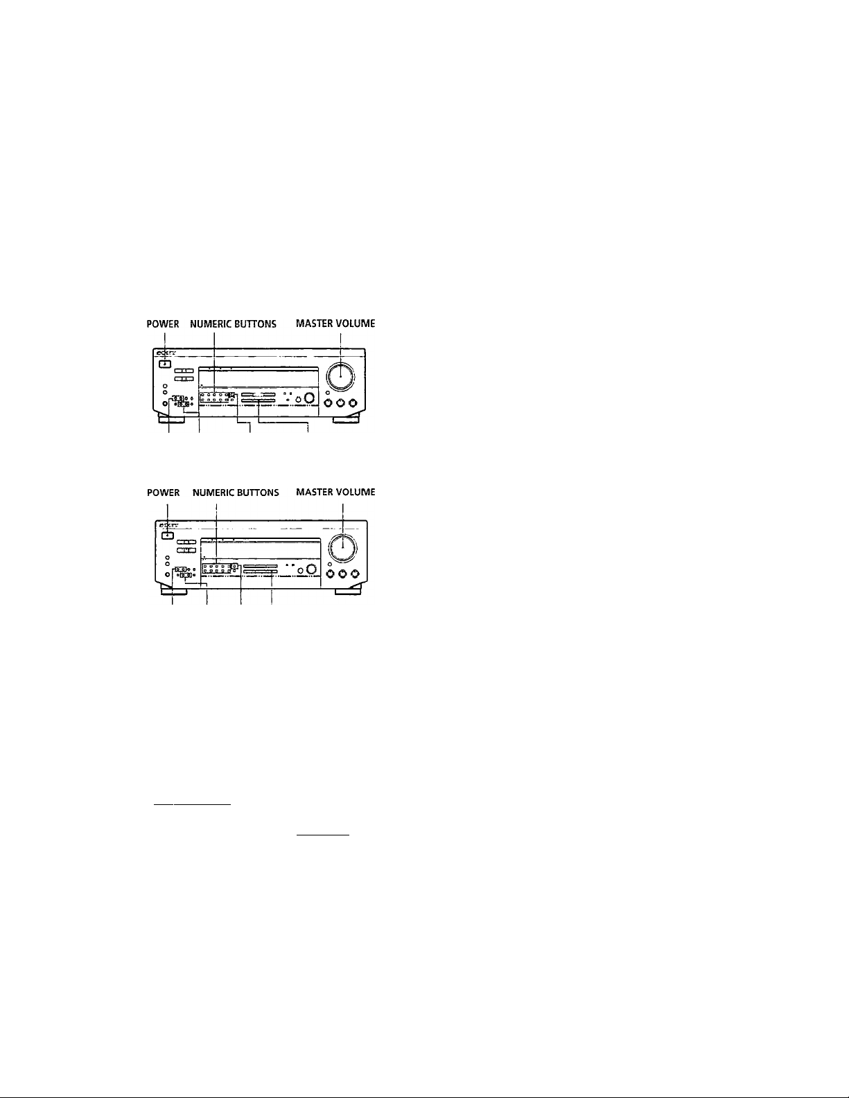
This receiver lets you enter a station's frequency
directly by using the numeric buttons (direct tuning). If
you don't know the frequency of the station you want,
see "Receiving broadcasts by scanning stations
(automatic tuning)" on this page.
Before you begin, make sure you have:
• Connected an FM/AM antenna to the receiver as
indicated on page 5.
• Selected the appropriateispeaker system. (See
"Selecting the speaker system" on page 7.)
EXCEPT STR-DE315
6 When you tune in AM stations; adjust the
direction of the AM loop antenna for optimum
reception.
To receive other stations
Repeat Steps 3 to 5.
If the STEREO indicator remains off
^ Press FM MODE when an FM stereo broadcast is
received.
If an FM stereo program is distorted
The STEREO indicator flashes. Press FM MODE to
change to monaura! (MONO). You ^vill not have the
stereo effect but the distortion will be reduced. To
return to stereo mode, press this button again.
'Q' If you cannot tune in a station and the entered
numbers are flashing
Make sure you've entered the right frequency. If not
press DIRECT and re-enter the frequency you want.
If the entered numbers still flash, the frequency is not
used in vour area.
I
TUNING FM/AM DIRECT TUNER
+/-
STR-DE315
TUNING FM/AWI DIRECT TUNER
+/-
1 Press POWER to turn on the receiver.
2 Press TUNER.
The last received station is tuned in.
3 Press FM or AM to select FM or AM stations.
4 Press DIRECT.
5 Press the numeric buttons to enter the frequency.
Example 1: FM 102.50 MHz Example 2: AM 1350 kHz
11 \|Q [|2 I js I|o I (You don't have to enter
6 6 & b b
n~1D~IF~1
b b b
'Q' To watch FM simulcast TV programs
Make sure that you tune in the simulcast program both
on the TV (or the VCR) and on the receiver.
'O’ If you enter a frequency not covered by the tuning
interval
The entered value is automatically rounded up or dovm
to the closest covered value.
Tuning intervals for direct tuning are:
FM: 50 kHz intervals
Receiving broadcasts by scanning stations
(automatic tuning)
If you don't know the frequency of the radio station
you want, you can have the receiver scan all the
receivable stations to locate the one you want.
1 Press TUNER.
The last received station is tuned in.
2 Press FM or AM to select FM or AM.
3 Press TUNING + or -.
Press the + button for a higher station number;
press the - button for a lower one. When you tune
past either end of the band, the receiver
automatically jumps to the opposite end. Every
time a station is received, the receiver stops
scanning. To continue scanning, press the button
again.
11
EN
Page 12
Receiver Operations
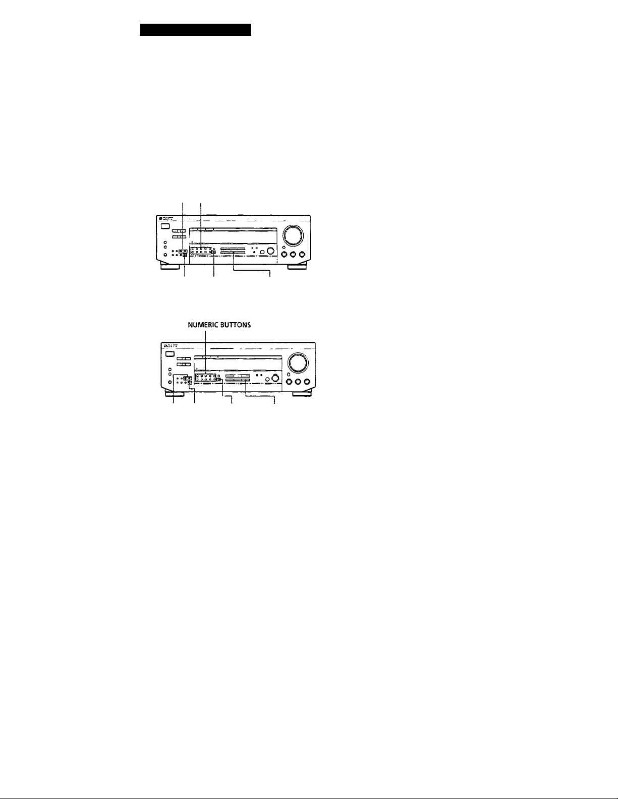
Presetting Radio Stations
To change a preset station
Preset a new station on the number you want to change.
You'll most likely want to preset the receiver with the
radio stations you listen to often so that you don't have
to tune in the station every time. The receiver can store
a total of 30 FM or AM stations. You can store the
stations on preset numbers combining 3 characters (A,
B, C) and numbers (0 - 9). For example, you can store a
station as preset number Al, B6 or C9, etc. *
EXCEPT STR-DE315
PRESET TUNING NUMERIC BUTTONS
MEMORY SHIFT TUNER
STR-DE315
Note
If the AC power cord is disconnected for about one week,
the preset stations will be cleared from the receiver's
memory, and you will have to preset the stations again.
Tuning preset stations (preset tuning)
You can tune diredtly to a preset station by entering its
preset number. If you don't know which stations are
preset on whichjiumbers, you can tune by scanning
the preset stations.
1 Press TUNER.
The last received station is tuned in.
2 Press SHIFT to select a character (A, B or C), then
press the number.
For example, select A and then press 7 to tune in
the station preset as .A7.
y'You can tune by scanning the preset stations
First press TUNER and then press PRESET TUNING +
or - to select the station you want. Each time you press
the buttons, the preset numbers change as follows:
. Al<
■ A2^... — AO • ► Bl- -B2—• . • B0<
-C0- ■ C2-—O
12f~
PRESET MEMORY SHIFT TUNER
TUNING
1
Press TUNER.
The last received station is tuned in.
2
Tune in the station you want.
If you are not familiar with how to tune in a
station, see "Receiving Broadcasts" on the
previous page.
Press MEMORY.
"MEMORY" appears for a few seconds.
Do steps 4 and 5 before "MEMORY" goes out.
Press SHIFT to select a character (A, B or C).
Each time you press SHIFT, the letter "A," "B" or
"C" appears in the display.
If “MEMORY" disappears, start again from step 3.
While MEMORY is displayed, press the number
5
you want to use (0 to 9).
6 Repeat Steps 2 to 5 to preset other stations.
Page 13
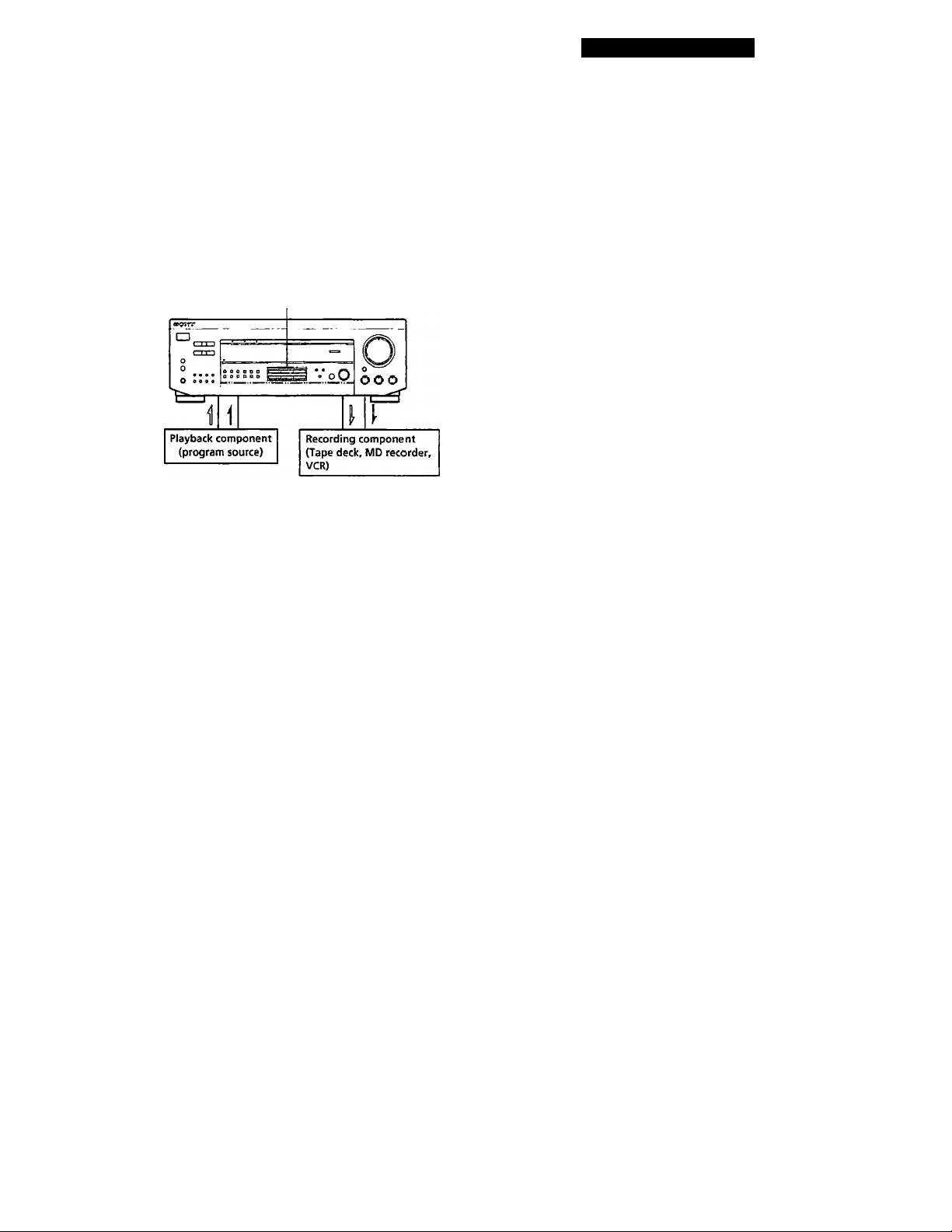
Recording
This receiver makes it easy to record to and from the
components connected to the receiver. You don't have
to connect playback and recording components
directly; once you select a program source on the
receiver, you can record and edit as you normally
would using the controls on each component
Before you begin, make sure you've connected all
components properly.
FUNCTION BUTTONS
Audio signal flow
Video signal flow
Recording on an audio tape or MiniDisc
You can record on a cassette tape or MiniDisc using the
receiver. See the instruction manual of your tape deck
or MD recorder if you need help.
Receiver Operations
Recording on a video tape
You can record TV program or digital broadcasting
system using the receiver. You can also add àudio from
a variety of audio sources when editing a video tape.
See your VCR's instruction manual if you need help.
1 Press TV / DBS to select the program sou ree.
2^ Set the component to be ready for playing.
For example, turn on the Ty and tuner.
3 Insert a blank video tape into the VCR for
recording. '
4 Start recording on the VCR.
'Q' You can replace audio while editing a video tape
At the point you want to start adding d ifferent sound,
press another function button (for example. CD) and
start playback. The sound from the selected component
will be recorded over the original audio.
To resume recording the original sound, press the
TV/DBS function button.
Note:
You cannot record the audio and video signal during
5.1 / DVD mode.
1 Press one of the function buttons to select the
program source.
2 Set the component to be ready for playing.
For example, insert a CD into the CD player.
3 Insert a blank tape or disc into the recording deck
and adjust the recording level, if necessary.
4 Start recording on the recording deck and then
start playing the component.
13'
Page 14
Using Surround Sound |
Choosing a Surround Mode
You can take advantage of suffoimd sound simply by
selecting one of the three pre-programmed surround
modes according to the type of music you wish to play,
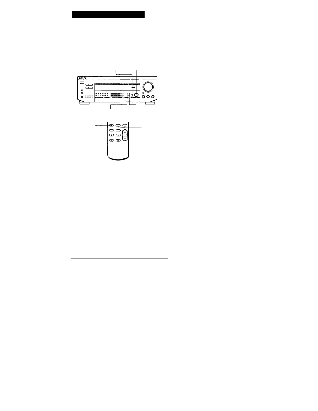
SURROUND MODE SURROUND ON/OFF
STR-DE415 / DE315 / D360Z only
PRO LOGIC* — C. STUDIO — HALL
[i;
• "DOLBY" appears in the display.
** "S HALL" and "L HALL" appears in the display.
To turn off surround sound
Press SURROLRMD ON/OFF.
You can find Dolby Surround-encoded software by
looking at the packaging
However, some rlideos and laser discs may use Dolby
Sunound sound even if it's not indicated on the
package. ,
□
EFFECT/DELAY TIME SET-UP
SURROUND
ON/OFF
SURROUND
MODE
Press SURROUND ON/OFF to turn on the
surround sound.
One of the SUR (surround) MODE indicators
lights up in the display.
Press SURROUND MODE repeatedly until the
indicator for the surround mode you want lights
up.
Select the appropriate surround mode as follows:
Select To
PRO LOGIC"
C. STUDIO Add die acoustic reflections of a cinema
HALL
Decode programs processed with Dolby
Surround and create the atmosphere of a
movie theater.
studio to decoded Dolby Surround signals.
Reproduce the acoustics of a rectangular
concert hall. Ideal for soft, acoustic sounds.
Note
Make sure to select speaker A with the SPEAKERS A button,
otherrNise, vou can't obtain the surround effect.
Adjusting the Effect Level (for C. STUDIO and HALL only)
You can make the surround sound more prominent by
increasing the EFFECT level. This control lets you
adjust the "presence" of the surround effect in six steps
(1-6).
1 Start playing a programme source,
2 Press EFFECT / DELAY TIME to select the level
you prefer.
The effect level ("EFFECT 1" ... "EFFECT 6")
appears on the display.
Note
Changing the effect level may not produce maior variations
in the surround effect when used with certain playback
sources.
14-
* "DOLBY" appears in the display.
When you use the remote
Each time you press SURROUND MODE, surround
mode changes as follows:
STR-DESIS only
PRO LOGIC*— C. STUDIO A —C. STUDIO B
LARGE HALL** —SMALL HALL**
EN
Page 15
Getting the Most Out of Dolby
Pro Logic Surround Sound
To obtain the best possible Dolby Pro Logic Surround
sound, first select the center mode according to the
speaker system you have. Tlien, adjust each speaker
volume and delay time.
Note that you must have at least one additional pair of
speakers and/or one center speaker to do the following
adjustments.
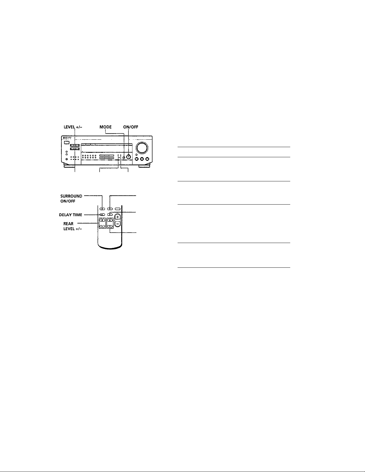
CENTER SURROUND SURROUND
Selecting the center mode
The receiver offers you four center modes: Phantom, 3
Channel Logic, Normal, and Wide. Each mode is
designed for a different speaker configuration. Select
the mode that best suits your speaker's system
configuration:
1 Press SURROUND ON/OFF to turn on surround
^ sound.
2 Press SURROUND MODE repeatedly to select the
Dolby surround sound field (PRO LOGIC or
C. STUDIO mode). '
3 Press SET-UP repeatedly until the set-up you
want appears in the display. Select the set-up as
follows:
REAR EFFECT/
LEVEL+/- DELAY TIME
SET-UP
' SURROUND
MODE
■ TEST TOME
CENTER
LEVEL +/-
If you have
Front and rear
speakers, no
center speaker
From and center
speakers, no rear
speaker
Front and rear
speakere, and a
small center
speaker
Front and rear
speakers, and a
large center
speaker
Select So that
PHANTOM The sound of the
3 CH LOGIC
(3 channel
Logic)
NORMAL
WIDE
center channel is
output from the front
speakers.
The sound of the rear
channel is output
from the front
speakers.
The bass sound of the
center channel is
output from the front
speakers (because a
small speaker cannot
produce enough
bass).
For "complete"
Dolby Pro Logic
Surround sound.
(continued)
15"
Page 16

Using Surround Sound
Adjusting the speaker volume
Tlie test tone feature lets you set the volume of your
speakers to the same level. (If all of your speakers have
equal performance, you don't have to adjust the
speaker volume.)
Using the controls on the remote lets you adjust the
volume level from your listening position.
I
1 Select the PRO LOGIC mode (see "Choosing a*
Surround Mode" on page 14) and select the
appropriate center mode (see "Selecting the
Center Mode" on page 15).
2 Press TEST TONE on the remote.
You will hear the test tone from each speaker
sequentially.
3 Adjust the volume level so that the test tone from
each speaker is at the same level from your
listening position.
• To adjust the level of center speaker, press
CENTER LEVEL + or - on the remote.
• To adjust the level of rear speakers, press
REAR LEVEL + or - on the remote.
4 Press TEST TONE on the remote to turn off the
test tone.
Adjusting the delay time
You can make the surround sound more effective by
delaying the output from the rear speakers (delay
time). You can select from three delay times, S (15 mS),
M (20 mS), and L (30 mS). For example, if you've
placed the rear speakers in a large room or apart from
your listening position, set the delay time shorter.
1 Start playing a program source encoded with
Dolby Surround sound.
2 Press DELAY TIME on the remote or EFFECT/
DELAY TIME on the receiver repeatedly to
choose the delay time parameter. The current
delay time appears in the display, such as
"DELAY S," "DELAY M" or "DELAY L."
Note
Select the PRO LOGIC mode when you adjust the delay time
using EFFECT/DELAY TIME on the receiver.
16'
You can adjust all speakers at one time
Adjust MASTER VOL on the remote or MASTER
VOLUME on the receiver.
You can also adjust the volume level with the
controls on the receiver
After pressing TEST TONE on the remote, press REAR
LEVEL + or - and CENTER LEVEL + or - to adjust the
level of the rear and center speakers respectively.
You can increase the output level of the rear
speakers
The adjustment range of the rear speakers is preset from
-15 to +10, but you can shift the range up 5 levels (-10
to +15). Hold down MODE on the receiver while
turning on the power until "GAIN UP" appears on the
display.
The values for the rear level remain fixed at -15 to +10
in the display, but you will be able to hear the
difference in the actual output level.
To reset the rear level adjustment range, repeat this
procedure to display "NORMAL".
EN
Page 17

Additional Information
Troubleshooting
If you experience any of the following difficulties while
using the receiver, use this troubleshooting guide to
help you remedy the problem. Should any problem
persist, consult your nearest Sony dealer.
There's no sound or only a very low-level sound is heard.
Check that the speakers and components are
connected securely.
"► Make sure you select the correct component
on the receiver.
^ Make sure you set the SPEAKERS selector
correctly, (see page 7)
^ Press MUTING on the remote if "MUTING"
is displayed.
^ The protective device on the receiver has been
activated because of a short circuit.
("PROTECT" flashes.) Turn off the receiver,
eliminate the short-circuit problem and turn
on the power again.
The left and right sounds are unbalanced or reversed.
^ Check that the speakers and components are
connected correctly and securely.
“♦ Adjust the BALANCE control.
Severe hum or noise is heard.
^ Check that the speakers and components are
connected securely.
"► Check that the connecting cords are away
from a transformer or motor, and at least 10
feet (3 meters) away from a TV set or
fluorescent light.
Place your TV away from the audio
components.
^ Make sure you connect a ground wire to the
antenna ground terminal.
The plugs and jacks are dirty. Wipe them
with a cloth slightly moistened with alcohol.
No sound is heard from the center speaker.
Select the appropriate center mode (see page
15).
“*■ Adjust the speaker volume appropriately (see
page 16).
Radio stations cannot be tuned in.
Check that the antennas are connected
securely. Adjust the antennas and coimect an
outdoor antenna if necessary.'
The signal strength of the stations is too weak
(when you tune in with automatic tuning).
Use direct tuning.
^ Make sure you set the tuning interval
correctly (when you tune in AM stations with
» automatic tuning) (.see.pages 11 and 18).
”► No stations have been j^reset or the preset
stations have been cleared (when you tune in
with scanning preset^stations). Preset the
stations (see page 12).
Surround effect cannot be obtained.
Make sure you turn on the sound field
function.
Make sure that the front speakers are
connected to the SPEAKERS A terminal.
“► Make sure that SPEAKERS A and B buttons
are depressed when two sets of front speakers
are used.
No picture or an unclear picture is seen on the TV screen.
^ Select the appropriate function on the
receiver.
^ Place your TV away from the audio
components.
Recording cannot be made.
Check that the components are connected
correctly.
The remote does not function.
“► Point the remote at the remote sensor S on
the receiver.
Remove the obstacles In the path of the
remote and the receiver.
Replace both batteries in the remote with new
ones if they are weak.
^ Make sure you select the correct function on
the remote.
"► Pressing TV CONTROL sets the remote to
operate the TV only. In this case, press one of
the SYSTEM CONTROL FUNCTION buttons
before operating the receiver (etc.).
No sound or only a very low-level sound is heard from
the rear speakers.
Select the appropriate center mode (see page
15).
^ Adjust the speaker volume appropriately (see
page 16).
^ Make sure you turn on the .sound field
surround mode function.
17
rW
Page 18

18
FW
Specifications
Amplifier section
stereo mode (8 ohms at 20 Hz
20 kHz less than 0.09%
total harmonic distortionj
lOOW + lOOW
(STR-DE515/DE415/
D360Z)
60W-r60W
(STR-DE315)
Surround mode (8 ohms at 1 kHz, THD
5.1/DVD* mode (8 ohm at 1 KHz, THD
Frequency
response
Inputs
_________________________
PHONO** 2.5 mV 50 74 dB
(MM) kilohms 72 dB*
CD,
5.1/DVD*
TAPE/MD, 150 mV
TV/
DBS, VIDEO
0.8%)
Front
STR-DE515:
lOOW/ch
STR-DE415 /D360Z:
lOOW/ch
STR-DE315:
Center (Pro Logic Mode)
Center lOOW/ch
Rear 50W/ch
TV/DBS,CD,TAPE/
Sensitivity Impedance SIN
200 mV
60W/ch
STR-DE515;
lOOW
STR-DE415 /D360Z:
100 W
STR-DE315:
60W
Rear
STR-DE515;
50W/ch
STR-DE415 /D360Z;
100 W
STO-DE315:
60W
0.8%)
Front lOOW/ch
PHONO": RIAA
equalization curve
±05 dB
MD, VIDEO, 5.1/DVD*
10 Hz - SO kHz ±1 dB
(weighting
network,
input level)
(A, 25 mV)
50 82 dB
kilohms 82 dB*‘*
(A, 150 mV)
• 78 IHF
Outputs
Muting Full mute Power
BASS BOOST *»^10 dB at 70 Hz
TONE ±8 dB at 100 Hz and
FM tuner section
Tuning range 87.5 -108.0 MHz
Antenna
terminals
Sensitivity
Usable sensitivity11.2dBf,2pV (IHF)
S/N
Harmonic
distortion at
1 KHz Seperation
Frequency
response
Selectivity
AM tuner section
Tuning range 530 • 1710 kHz
Antenna Loop antenna
Usable sensitivity 50 dB/m (at l/»0 kHz)
S/N 54dB(at50mV/m)
Harmonic
distortion
Selectivity At 10 kHz: 40 dB
Video section (except STR-DE315)
InpiiU VIDEO, TV/DBS, 5.1/
Outputs VIDEO:
TAPE/MD REC OUT:
Voltage: 150 mV,
Impedance: 10 kilohms
VIDEO AUDIO OUT:
Voltage: 150 mV,
Impedance: 10 kilohms
WOOFER/MIX AUDIO
OUT (STR-DE515/
DE415)
Voltage: 2 V
Impedance: 10 kilohms
PHONES; Accepts low
•
and high impedance
headphones |
10 kHz
75 ohms, unbalanced
300 ohms, balanced
Mono: lS3dBf,4.5pV
Stereo: 36.3 dBf, 45 pV
Mono: 76 dB
Stereo: 70 dB
Mono: 0.3 %
Stereo: 0.5 % accessories AM loop antenna (1)
45 dB at 1 kHz
30 Hz-15 kHz "dB
60 dB al 400 kHz
(lOkHzSTEP)
0.5 % (50 mV/m,
400 Hz)
DVD*:
1 Vp-p75ohms
1 Vp-p 75 ohms
MONITOR:
1 Vp-p 75 ohms
General
System
Power
1 requirements
consumption
%
AC outlets
Dimensions
Mass (Approx.)
Supplied
• 5.1 /DVD is for STR-DE515 only.
” except STR-DE315
Design and spedAcations are subject to
change without notice.
Tuner section: PLL
quartz-locked digital
synthesizer system
Preamplifier section:
Low-noise NF type
equalizer
Power amplifier section:
Pure-complimentary
SEPP
120 V AC, 60 Hz
STR-DE515:
330 VA
STR-DE415/D3602:
285 VA
STR-DE315:
220 VA
1 switched, total 120 W /
lAMax
430x148x295 mm
(17x57ixll V*
inches)
STR-DE515:
7.9 kg (17 lb 6 oz)
STR-DE415/D360Z:
7.4 kg (16 lb 5 02)
STR-DE315:
6.1 kg (13 lb 7 oz)
FM wire antenna (1)
Remote controller
(remote) (1)
Size AA (R6) batteries (2
Page 19
Additional
Glossary
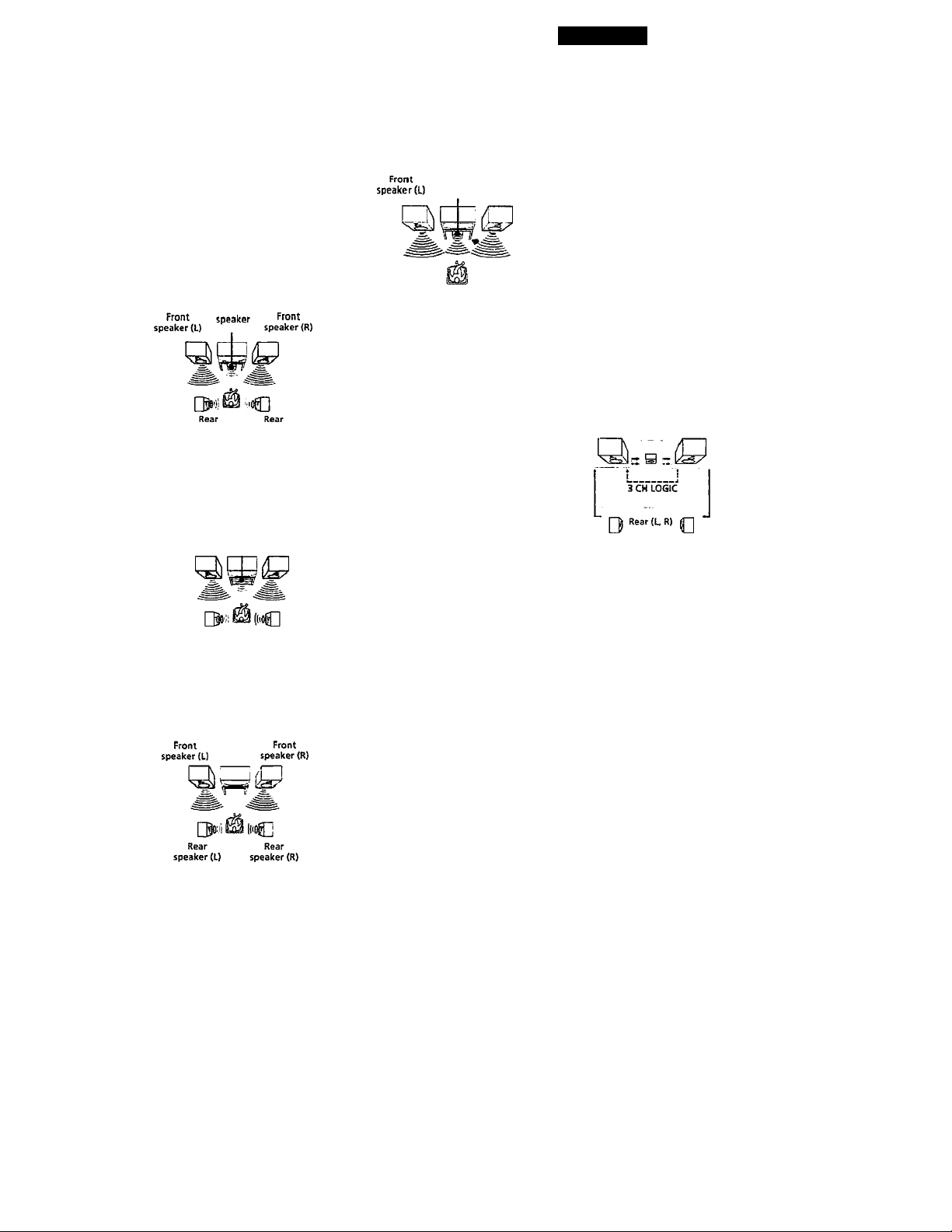
Center mode
Setting of speakers to en>iance Dolby Pro
Logic Surround mode. To obtain the best
possible surround sound, select one of the
following four center modes according to
your speaker system.
• NORMAL mode
Select NORMAL mode if you have front
and rear speakers and a small center
speaker. Since a small speaker cannot
produce enough bass, the bass sound of
the center channel is output from the front
speakers.
Center
speaker (L) speaker <R)
WIDE mode
Select WIDE mode il you have front and
rear speakers and a large center speaker.
With the WIDE mode, you can lake full
advantage of Dolby Surround sound.
Center
Front speaker Front
speaker (L) speaker (R)
Rear Rear
speaker (1) speaker (R)
PHANTOM mode
Select PHANTOM mode if you have front
and rear speakers but no center speaker.
The sound of the center channel ts output
from the front speakers
3 CH LOGIC mode
Select 3 CM LOGIC mode if you have front
and contor speakers but no rear speaker.
The sound of the rear channel is output
from the front speakers to let you
experience some of the surround sound
without using rear speakers.
speaker
Delay time
Time lag between the surround sound output
from front speakers and rear speakers. By
adjusting the delay time of the rear speakers,
you can obtain the feeling of presence. Make
the delay time longer when you have placed
the rear speakers m a small room or close to
your listening position, and make it shorter
when you hove placed them in a large room
or apart from your listening position.
Oirea tuning
Tuning method to let you directly entera
station's frequency using the numeric
buttons. Use this method if you know the
frequency of the station you want.
Dolby Pro Logic Surround
Decoding system of Dolby Surround sound
standardi2ed in TV programs and movies.
Compared with the former Dolby Surround
S)'Stcm, Dolby Pro Logic Surround improves
sound image by using four separate channels:
off-screen audio effects, on-screen dialog,
ieft-to-right panning, and music. These
channels manipulate the sound to be heard
and enhance the action as it happens on the
screen. To take advantage of Dolby Pro Logic,
you should have at least one pair of roar
speakers and/or one center speaker. You also
need to select the appropriate center mode to
enjoy a full effect.
5.1 INPUT
Jacks used to input the audio signals that are
decoded from the Dolby Digital AC'3 format
audio. The jacks are usually connected with
an AC-3 decoder or a DVD player equipped
with an AC-3 decoder. Tliis connection
enables the amplifier to reproduce 5.1
channel surround sounds.
Preset station
A radio broadcasting station that is stored in
memory of the receiver. Once you "preset"
stations, you no longer have to tune in the
station-s. Each preset station is assigned its
own preset number, which lets you tune
them in quickly.
Surround sound
Sound that consists of three elements: direct
sound, early reflected sound (early
reflections) and reverberalivc .sound
(reverberation). The acoustics where you hear
the sound affect the way these three sound
elements are heard. These sound elements are
combined in such a way that you can actually
feel the size and the t)T>e of a concert hall.
Front
Types of sound
Early reflections
Direct sound
Reverberation
Transition of sound from rear speakers
Direct sound Early
Level t reflections Reverberation
Early reflection time
Test tone
Signal given out by the receiver for adjusting
the speaker volume. The te.st tone will come
out as follows:
» in a system with a center speaker
(NORMAUWIDE/3 CH LOGIC modes)
The test tone is output from the front L
(left), center, front R (right), and rear
speakers in succession
Fronts Front (R)
Center
NORMAL/WIDE
In a system without a center speaker
(PHANTOM mode)
The test tone is output from the front and
the rear speakers alternately
Front (L, R)
□ Rear(UR)0
Time
PHANTOM
19
cN
Page 20

Index
A, B
Adjusting
delay time 16
speaker volume 16
tone 9
volume 8
Antenna hookups 5
Audio component hookups 5,
6
Automatic tuning 11
Background operation 10
Center mode 15,19
NORMAL mode 15,19
PHANTOM mode 15,19
3CH LOGIC mode 15,19
WIDE mode 15,19
Connecting. See Hookups
Delay time 16,19
Direct tuning 11,19
Dolby Pro Logic
Surround 19
getting the most out of 15
Dolby Surround sound 14,19
center mode 16,19
Dubbing. See Recording
E, F. G
Editing. See Recording
H, I, J, K, L, M
Hookups
AC power cord 8
antennas 5
audio components 5,6
overview 4
speakers 6, 7
video component 7
N, O
NORMAL mode 15,19
PHANTOM mode 15, 19
Preset station 19
Presetting
radio stations 12
Preset tuning 12
Program source
selecting 8,9
Quick reference guide 23
Random Music Sensor 22
Rear panel 5,6,7,8, 21
Receiving broadcasts
directly 11
using preset stations 12
Recording
on a tape 13
on a video tape 13
Remote buttons 9,10, 22
background operation 10
Scanning
preset stations 12
radiostations 11
Selecting a program source 8
using the remote 9
Speakers
connection 6, 7
impedance 18
placement 6
selecting speaker system 7
Storing radio stations. See
Presetting
Surround sound 14,19
Test tone 16,19
3CH LOGIC mode 15,19
Troubleshooting 17
Tuning. See Receiving
broadcasts
u
Unpacking 4
V
Video component hookups 7
w, X, Y. Z
Watching/Ustening to video
programs 9
WIDE mode 15,19
20
EN
Page 21
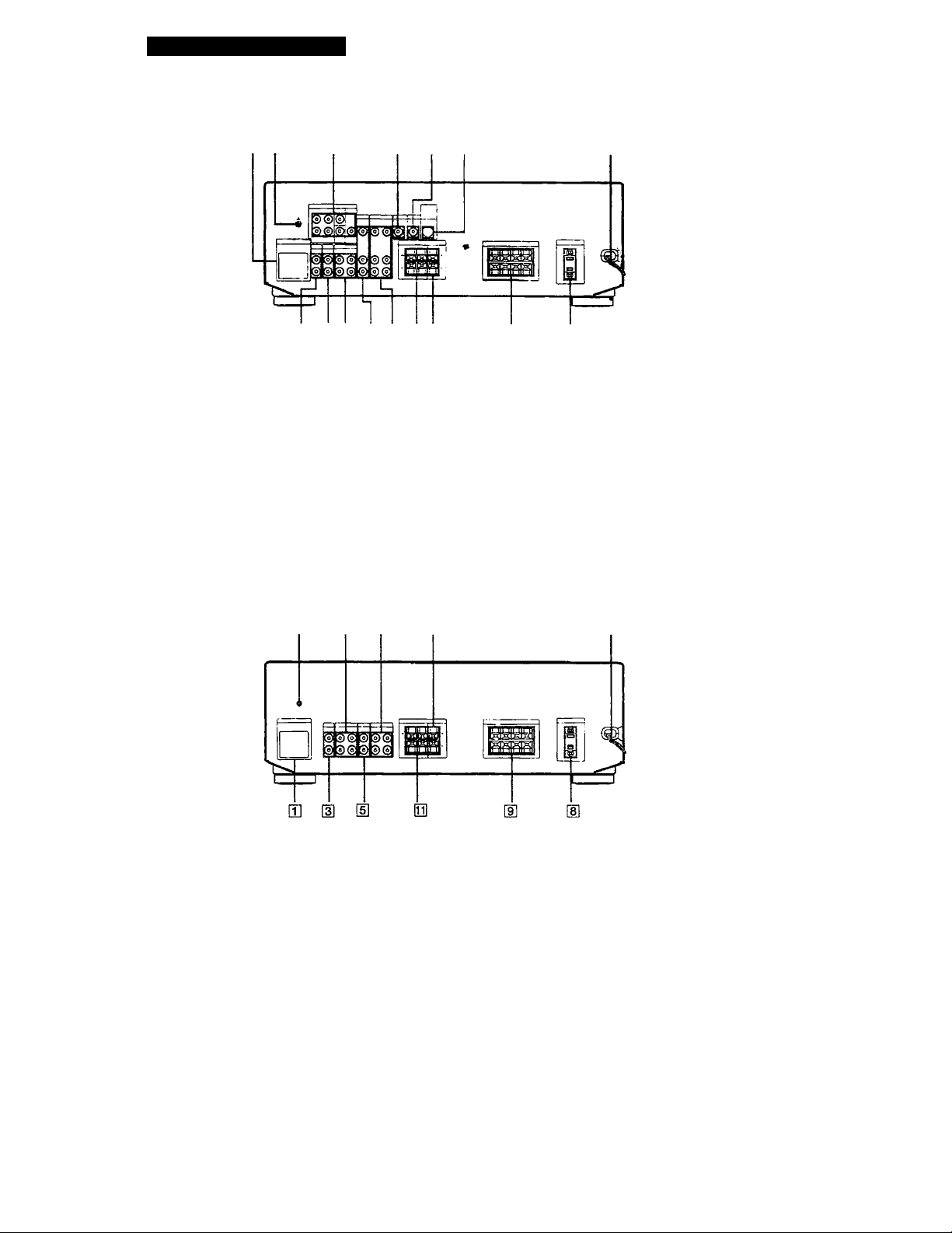
Rear Panel Descriptions
STR- DE515/DE415/D360Z
Hj [2
in ANTENNA (AM/FM)
[2] ih ground terminal
[3] PHONO
®CD
m TAPE/MD
H TV/DBS
E] VIDEO
® MONITOR
STR- DE315
m
S] d] SI H] 51 El 51
HI 5,1/DVD (Audio/Video) 51 FRONT SPEAKERS (A/B)
(STR-DE515 only)
0 WOOFER (Audio Out) (CENTER)
(STR-DE515 only)
MIX OUT (Audio Out) (REAR)
(STR-DE415only)
51 AC power cord (STR-DE515 only)
ig SWITCHED AC OUTLET
E B3
m
51
51 SURROUND SPEAKER
51 SURROUND SPEAKERS
51 WIRELESS REAR SPEAKERS
[2] g]
[H ANTENNA (AM/FM) E VIDEO
m ih ground terminal lYI AC power cord (CENTER)
[U CD
[4] TAPE/MD
H TV/DBS
E SWITCHED AC OUTLET 51 SURROUND
E FRONT SPEAKERS (A/B)
H
m
g SURROUND
(REAR)
21
EN
Page 22

Button Descriptions }-
For buttons not described on previous pages and buttons with names different from the buttoas on the main unit.
Remote
Button
0-9 Receiver
>10 CD player/
CH/PRESET
+ /-
D, SKIP
DISC
i« CD player/
II
► CD player/
■ CD player/
•
Operates
CD player/MD
recorder/DVD
player
TV/VCR/DBS
Tape deck/
MD recorder
Receiver Scans and selects preset
TV/VCR/DBS
CD player Skips discs (CD player
CD player
CD player/
DVD player
Tape deck/MD
recorder/VCR
MD recorder
CD player/
Tape deck/MD
recorder/VCR/
DVD player
Tape deck/MD
recorder/VCR/
DVD player
Tape deck/MD
recorder/VCR/
DVD player
Tape deck
Tape deck
Tape deck/
MD recorder/
VCR
Function
Selects preset numbers.
Selects track numbers.
0 selects track 10.
Selects channel numbers.
Selects track numbers
over 10.
stations.
Selects preset channels.
with multi-disc changer
only).
Select discs (Mega storage
CD player only).
Searches tracks (forward
or backward).
Fastforwards or rewinds.
Skips tracks.
Pauses play or record.
(Also starts recording
with components in
record standby.)
Starts play.
Stops play.
Starts play on the reverse
side.
Sets tape decks to the
record standby mode.
Starts recording when
pressed with ► (or
on tape deck).
Remote
Operates Function
Button
RMS
DIRECTION
RMS CLEAR
RMS/START Tape deck
ENTER
TV/VIDEO TV/VCR Selects input signal: TV
VISUAL
POWER
TV CONTROL TV
SL^B CH +/-
POSITION
SWAP
PINP
JUMP
ANTTV7VTR
RMS: Random .Music Sensor
Tape deck
Tape deck
i
%
TV/VCR/DBS Changes channels when
TV/VCR/
LD Player/DBS/
DVD player
TV
TV
TV
TV
TV Activates the picture-in-
TV Jumps back and forth
VCR Selects output signal from
Selects tape direction (for
tape decks with the RMS*
function.)
Gesrs RMS" program (for
tape decks with the RMS
function.)
Programs tracks (tape
deck with the RMS*
function only).
used with 0*9.
input or video input.
Turns on or off the power.
Turns on the TV, switches
the input to "TV/’ and
sets the remote to operate
the TV.
Selects the channel entry
mode, either one or two
digit (in Europe only).
Selects preset channels for
the small picture.**
Changes the position of
the small picture.’'"
Swaps the small and the
large picture.**
picture function.**
between the previous and
current channels.
the antenna terminal: TV
signal or VCR program.
' Only for Sony TVs with the picture-in-picture function
22'
Page 23

Quick Reference Guide
Receiving Broadcasts Presetting Radio
(direct tuning) Stations
Example: Receiving FM
102.50 MHz
♦
FM
Select FM.
' in
Display
r j n n c n
rn luc.ju.
Example; Presetting a
station as A7
Tune in the station you want.
MEMORY
I 1
♦
srapr
Select A.
Scanning Radio Receiving Preset
Stations (automatic tuning) Stations
Selecting a
Component
Example 1: Playing a CD
Turn oi( the CD player.
♦
Start playing.
Example 2: Watching a video
tape
Turn on the VCR.
Start playing.
Using Pre-programmed Sound Fields
Example: Scanning FM
stations
♦
FM
□ Select FM.
♦
TUNING +
I I I
^ To continue
- TUNING +
scanning.
Example; Receiving the
station number A7
♦
SHIFT
3 Select A.
Scanning Preset Stations
- PRESET TUNING +
Example: Watching the
video tape of a
Dolby Surroundencoded movie
ON/OFF
Select
C.STUDIO
Turn on the VCR.
♦
Start playing.
23
fW
 Loading...