


3-860-516-12(1)
FM Stereo
FM-AM Receiver
Operating Instructions
STR-DE915
STR-DE715
STR-DE615
STR-D660Z
STR-D560Z
1997 by Sony Corporation
WARNING
To prevent fire or shock hazard, do not expose the unit to rain or moisture.
This symbol is intended to alert the user to the presence of uninsulated “dangerous voltage” within the product’s enclosure that may be of sufficient magnitude to constitute a risk of electric shock to persons.
This symbol is intended to alert the user to the presence of important operating and maintenance (servicing) instructions in the literature accompanying the appliance.
INFORMATION
This equipment has been tested and found to comply with the limits for a Class B digital device, pursuant to Part 15 of the FCC Rules.
These limits are designed to provide reasonable protection against harmful interference in a residential installation. This equipment generates, uses, and can radiate radio frequency energy and, if not installed and used in accordance with the instructions, may cause harmful interference to radio communications. However, there is no guarantee that interference will not occur in a particular installation. If this equipment does cause harmful interference to radio or television reception, which can be determined by turning the equipment off and on, the user is encouraged to try to correct the interference by one or more of the following measures:
–Reorient or relocate the receiving antenna.
–Increase the separation between the
equipment and receiver.
–Connect the equipment into an outlet on a circuit different from that to which the receiver is connected.
–Consult the dealer or an experienced radio/TV technician for help.
CAUTION
You are cautioned that any changes or modification not expressly approved in this manual could void your authority to operate this equipment.
Note to CATV system installer:
This reminder is provided to call CATV system installer’s attention to Article 820-40 of the NEC that provides guidelines for proper grounding and, in particular, specifies that the cable ground shall be connected to the grounding system of the building, as close to the point of cable entry as practical.
Owner’s Record
The model and serial numbers are located on the rear of the unit. Record the serial number in the space provided below. Refer to them whenever you call upon your Sony dealer regarding this product.
Model No. STR-DE915/STR-DE715/
STR-DE615/STR-D660Z/
STR-D560Z
Serial No.
For the customers in Canada
CAUTION
TO PREVENT ELECTRIC SHOCK, DO NOT USE THIS POLARIZED AC PLUG WITH AN EXTENSION CORD, RECEPTACLE OR OTHER OUTLET UNLESS THE BLADES CAN BE FULLY INSERTED TO PREVENT BLADE EXPOSURE.
Precautions
On safety
•Should any solid object or liquid fall into the cabinet, unplug the receiver and have it checked by qualified personnel before operating it any further.
On power sources
•Before operating the receiver, check that the operating voltage is identical with your local power supply. The operating voltage is indicated on the nameplate at the rear of the receiver.
•The receiver is not disconnected from the AC power source as long as it is connected to the wall outlet, even if the receiver itself has been turned off.
•If you are not going to use the receiver for a long time, be sure to disconnect the receiver from the wall outlet. To disconnect the AC power cord, grasp the plug itself; never pull the cord.
•One blade of the plug is wider than the other for the purpose of safety and will fit into the wall outlet only one way. If you are unable to insert the plug fully into the outlet, contact your dealer.
•Should the AC power cord need to be changed, have it done at a qualified service shop only.
On placement
•Place the receiver in a location with adequate ventilation to prevent heat buildup and prolong the life of the receiver.
•Do not place the receiver near heat sources, or in a place subject to direct sunlight, excessive dust or mechanical shock.
•Do not place anything on top of the cabinet that might block the ventilation holes and cause malfunctions.
On operation
•Before connecting other components, be sure to turn off and unplug the receiver.
On cleaning
•Clean the cabinet, panel and controls with a soft cloth slightly moistened with a mild detergent solution. Do not use any type of abrasive pad, scouring powder or solvent such as alcohol or benzine.
If you have any question or problem concerning your receiver, please consult your nearest Sony dealer.
2

About This Manual
The instructions in this manual are for models STR-DE915, DE715, DE615, D660Z, and D560Z. Check your model number by looking at the upper right corner of the front panel. In this manual, the USA and Canadian STRDE915 and the programmable remote commander RM-P501 (supplied with the STR-DE915, DE715, and D660Z) are used for illustration purposes unless stated othewise. Any difference in operation is clearly indicated in the text, for example, “STR-DE915/DE715 (USA, Canada) only.”
Type of differences
|
Model |
DE915 DE715 |
D660Z |
|
Feature |
|
DE615 |
D560Z |
|
|
|
|
|
|
3 video inputs |
r |
|
|
|
Built-in Dolby |
|
|
|
|
Digital |
r |
|
|
|
processor |
|
|
|
|
|
|
|
|
|
Digital jacks |
r |
|
|
|
5.1 INPUT |
|
r |
r |
|
jacks |
|
|||
|
|
|
||
|
|
|
|
|
Control A1/ |
r* |
DE715* |
|
|
Control S |
|
|||
|
|
|
||
|
|
|
|
|
WIRELESS |
|
|
|
|
REAR |
r |
r |
|
|
SPEAKER |
|
|||
|
|
|
||
connector |
|
|
|
|
Programmable |
r |
DE715 |
D660Z |
|
remote |
|
|
|
|
* USA and Canadian models only
Conventions
•The instructions in this manual describe the controls on the receiver. You can also use the controls on the remote if they have the same or similar names as those on the receiver.
•A “Quick Reference Guide” is supplied on the back cover.
•The “Remote Button Descriptions” section on page 37 provides an overview of the remote buttons.
•The following icons are used in this
manual:
ZIndicates that you can use only the remote to do the task.
zIndicates hints and tips for making the task easier.
This receiver incorporates the Dolby* Pro Logic Surround system.
*Manufactured under license from Dolby Laboratories Licensing Corporation. DOLBY, the double-D symbol a, “AC-3,” and “PRO LOGIC” are trademarks of Dolby Laboratories Licensing Corporation.
TABLE OF CONTENTS
Getting Started
Unpacking 4
Hookup Overview 4
Antenna Hookups 5
Audio Component Hookups 5
Speaker System Hookups 6
TV/VCR Hookups 9
Digital Component Hookups (STR-DE915 only) 10
AC Hookups 11
Before You Use Your Receiver 11
Receiver Operations
Selecting a Component 12
Receiving Broadcasts 15
Presetting Radio Stations 16
Indexing Preset Stations and Program Sources 16
Recording 17
Using the Sleep Timer 18
Dolby Surround Setup
Dolby Digital (STR-DE915 only) 19
Dolby Pro Logic (STR-DE715/DE615/D660Z/D560Z only) 20
Sound Adjustment
Using Pre-programmed Sound Fields 22
Customizing the Sound Fields 25
Advanced Remote Operations
Operating One Component While Using Another (background operation)
29
Changing the Factory Setting of a FUNCTION Button 29 Programming the Remote (STR-DE915/DE715/D660Z only) 30
Additional Information
Troubleshooting 31 |
|
|
Specifications 32 |
|
|
Glossary |
33 |
|
Table of Functions of the SET UP Button 35 |
||
Rear Panel Descriptions 36 |
|
|
Remote Button Descriptions |
37 |
|
|
|
|
Index |
39 |
|
|
|
|
Quick Reference Guide |
Back cover |
|
3
Getting Started
Unpacking
Check that you received the following items with the receiver:
•FM wire antenna (1)
•AM loop antenna (1)
•Remote commander (remote) (1)
RM-P501 (STR-DE915/DE715/D660Z only) RM-U501 (STR-DE615/D560Z only)
•Size AA (R6) batteries (2)
•Audio/video cable (1) (STR-DE915/DE715 (USA, Canada) only)
•Control S cord (1)
(STR-DE915/DE715 (USA, Canada) only)
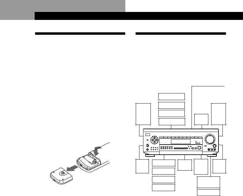
Inserting batteries into the remote
Insert two size AA (R6) batteries with the + and – on the battery compartment. When using the remote, point it at the remote sensor gon the receiver.
 ] } ]
] } ]

 }
}

zWhen to replace batteries
Under normal use, the batteries should last for about 6 months. When the remote no longer operates the receiver, replace both batteries with new ones.
Notes
•Do not leave the remote in an extremely hot or humid place.
•Do not use a new battery with an old one.
•Do not expose the remote sensor to direct sunlight or lighting apparatuses. Doing so may cause a malfunction.
•If you don’t use the remote for an extended period of time, remove the batteries to avoid possible damage from battery leakage and corrosion.
Hookup Overview
The receiver allows you to connect and control the following audio/video components. Follow the hookup procedures for the components that you want to connect to the receiver on the pages specified. To learn the locations and names of each jacks, see “Rear Panel Descriptions” on page 36.
|
TV/VCR Hookups (9) |
Antenna Hookups (5) |
|||||||||
|
Digital Component |
||||||||||
Speaker |
AM/FM antenna |
||||||||||
Hookups (10) |
|
|
|||||||||
System |
|
|
|
|
|
|
|
|
|
||
DVD player |
|
|
|
|
|
|
|
|
|||
Hookups |
|
|
|
|
|
|
|
|
|||
(6) |
TV |
|
|
|
|
|
|
|
|
|
|
|
|
|
|
|
|
|
|
|
|
||
Front |
VCR |
|
|
|
|
|
|
|
Front |
||
speaker |
|
|
|
|
|
|
speaker |
||||
|
|
|
Active |
|
|
||||||
(L) |
LD player |
|
|
|
|
|
(R) |
||||
|
|
woofer |
|
|
|
|
|
||||
|
|
|
|
|
MASTER VOLUME |
|
|
||||
|
|
|
|
|
4 • |
• • 5 |
• • |
• 6 |
|
|
|
|
|
|
|
|
• |
|
|
• |
• |
|
|
|
VIDEO 1 VIDEO 2 VIDEO 3 LD / DVD |
TV/DBS |
TAPE DAT / MD CD |
TUNER PHONO |
• |
|
|
|
• |
|
|
|
3 |
|
|
|
7 |
|
|||||
|
|
|
|
|
• |
|
|
|
• |
||
|
|
|
|
|
• |
|
|
|
|
• |
|
|
|
|
|
|
• |
|
|
|
|
• |
|
|
|
|
|
|
2 |
|
|
|
|
8 |
|
|
|
|
|
|
• |
|
|
|
|
• |
|
|
|
|
|
|
• |
|
|
|
|
• |
|
|
|
|
|
DIRECT PASS |
• |
|
|
|
|
• |
|
|
|
|
|
|
1 |
|
|
|
9 |
|
|
SPEAKERS |
|
|
|
DISCRETE |
• |
|
|
|
• |
|
|
g |
|
|
• |
|
|
|
|
|
|||
|
|
|
|
• |
|
|
• |
• |
BALANCE |
||
+ |
|
|
|
|
BASS 0 |
|
|
10 |
|||
|
|
|
SOUND FIELD |
BOOST |
|
|
|
|
|
||
|
|
|
|
ON / OFF |
|
|
|
|
|
|
|
+ |
+ |
|
|
GENRE MODE |
|
|
|
|
|
|
|
|
VIDEO FUNCTION |
AUDIO FUNCTION |
|
|
|
|
L |
R |
|||
PHONES |
|
|
|
|
|
|
|
|
|
|
|
|
|
|
|
|
VIDEO 3 INPUT |
|
|
|
|
|
|
Rear |
CD player |
Center |
Wireless |
|
|
|
|
Rear |
|||
speaker |
|
speaker |
rear |
|
|
|
|
speaker |
|||
(L) |
Tape deck |
|
|
speaker |
|
|
|
|
(R) |
||
DAT/MD deck |
|
|
Video camera |
||||||||
|
Turntable |
|
|
|
recorder |
|
|||||
|
|
|
|
|
|
|
|
|
|
||
Audio Component |
|
|
Video game |
||||||||
|
|
|
|
|
|
|
|
|
|||
Hookups (5) |
|
|
|
|
|
|
|
|
|
||
Before you get started
•Turn off the power to all components before making any connections.
•Do not connect the AC power cords until all of the connections are completed.
•Be sure to make connections firmly to avoid hum and noise.
•When connecting an audio/video cable, be sure to match the color-coded pins to the appropriate jacks on the components: Yellow (video) to Yellow; White
(left, audio) to White; and Red (right, audio) to Red.
4

Getting Started
Antenna Hookups
Overview
This section describes how to connect AM and FM antennas to the receiver. If you want to receive radio broadcasts with the receiver, complete these connections first, then go to the following pages.
ANTENNA
|
S-LINK |
TV/DBS LD/DVD VIDEO 2 |
|
VIDEO 1 |
|
MONITOR |
SURROUND SPEAKERS |
|
||
|
CTRL A1 |
CTRL S |
|
CTRL S |
CTRL S |
|
|
CTRL S |
|
|
|
|
STATUS IN |
|
OUT |
OUT |
|
|
IN |
|
|
|
|
|
|
|
|
S-LINK |
|
|
|
|
|
|
VIDEO |
VIDEO |
VIDEO |
VIDEO |
VIDEO |
VIDEO |
VIDEO |
WIRELESS |
IMPEDANCE |
|
|
IN |
IN |
OUT |
IN |
OUT |
IN |
OUT |
REAR |
SELECTOR |
|
|
|
|
|
|
|
|
WOOFER |
SPEAKER |
FRONT |
|
|
|
|
|
|
|
|
|
||
|
|
|
|
|
|
|
|
AUDIO |
|
|
|
|
AUDIO |
AUDIO |
AUDIO |
AUDIO |
AUDIO |
AUDIO |
OUT |
|
4 Ω 8 Ω |
|
SIGNAL |
IN |
IN |
OUT |
IN |
OUT |
IN |
|
|
|
|
GND |
|
|
|
|
|
|
|
|
|
|
|
|
|
|
|
|
|
L |
|
|
|
y |
|
|
|
|
|
|
R |
|
AC OUTLET |
|
|
|
|
|
|
|
|
|
||
|
AM |
IN |
IN |
REC OUT |
IN |
REC OUT |
IN |
|
|
|
|
|
|
|
|
|
|
|
L |
|
|
FM |
y |
|
|
|
|
|
|
R |
|
|
75Ω |
|
|
|
|
|
|
|
|
||
COAXIAL |
|
|
|
|
|
|
|
|
|
|
ANTENNA |
|
PHONO |
CD |
DAT / MD |
TAPE |
|
|
|
||
FRONT SPEAKERS
What antennas will I need?
• FM wire antenna |
• AM loop antenna |
(supplied) (1) |
(supplied) (1) |
Hookups
FM wire antenna |
Receiver |
AM loop antenna |
After connecting |
|
AM |
|
|
|
the wire antenna, |
|
|
keep it as |
FM |
y |
horizontal as |
75Ω |
|
COAXIAL |
|
|
|
|
|
possible. |
ANTENNA |
|
zIf you have poor FM reception
Connect a 75-ohm coaxial cable (not supplied) to an FM outdoor antenna.
FM outdoor antenna
Receiver |
|
|
AM |
FM |
y |
75Ω |
|
COAXIAL |
|
ANTENNA
Ground wire (not supplied)
v
To ground
Important
If you connect an outdoor antenna, ground it against lightning. To prevent a gas explosion, do not connect the ground wire to a gas pipe.
Notes
•Do not use ySIGNAL GND for this connection.
•To prevent noise pickup, keep the AM loop antenna away from the receiver and TV.
Audio Component Hookups
Overview
This section describes how to connect your audio components to the receiver. If you want to use the receiver as an amplifier, complete these connections.
Note for STR-DE915
For digital connections, see “Digital Component Hookups (STR-DE915 only)” on page 10.
S-LINK CTRL A1
(STR-DE915/DE715 (USA, Canada) only)
S-LINK |
TV/DBS LD/DVD VIDEO 2 |
|
VIDEO 1 |
|
MONITOR |
SURROUND SPEAKERS |
|
||
CTRL A1 |
CTRL S |
|
CTRL S |
CTRL S |
|
|
CTRL S |
|
|
|
STATUS IN |
|
OUT |
OUT |
|
|
IN |
|
|
|
|
|
|
|
S-LINK |
|
|
|
|
|
VIDEO |
VIDEO |
VIDEO |
VIDEO |
VIDEO |
VIDEO |
VIDEO |
WIRELESS |
IMPEDANCE |
|
IN |
IN |
OUT |
IN |
OUT |
IN |
OUT |
REAR |
SELECTOR |
|
|
|
|
|
|
|
WOOFER |
SPEAKER |
FRONT |
|
|
|
|
|
|
|
|
||
|
|
|
|
|
|
|
AUDIO |
|
|
|
AUDIO AUDIO AUDIO AUDIO AUDIO |
AUDIO |
OUT |
|
4 Ω 8 Ω |
||||
SIGNAL |
IN |
IN |
OUT |
IN |
OUT |
IN |
|
|
|
GND |
|
|
|
|
|
|
|
|
|
|
|
|
|
|
|
L |
|
|
y |
|
|
|
|
R |
AC OUTLET |
|
|
|
|
|
|
||
|
AM |
IN |
IN |
REC OUT IN |
REC OUT |
IN |
|
|
|
|
|
|
|
L |
|
FM |
y |
|
|
|
|
R |
|
75Ω |
|
|
|
|
|
||
COAXIAL |
|
|
|
|
|
|
|
ANTENNA |
|
PHONO CD |
DAT / MD |
TAPE |
|
|
|
|
|
|
|
|
|
|
FRONT SPEAKERS |
PHONO |
|
CD DAT/MD |
TAPE |
||||
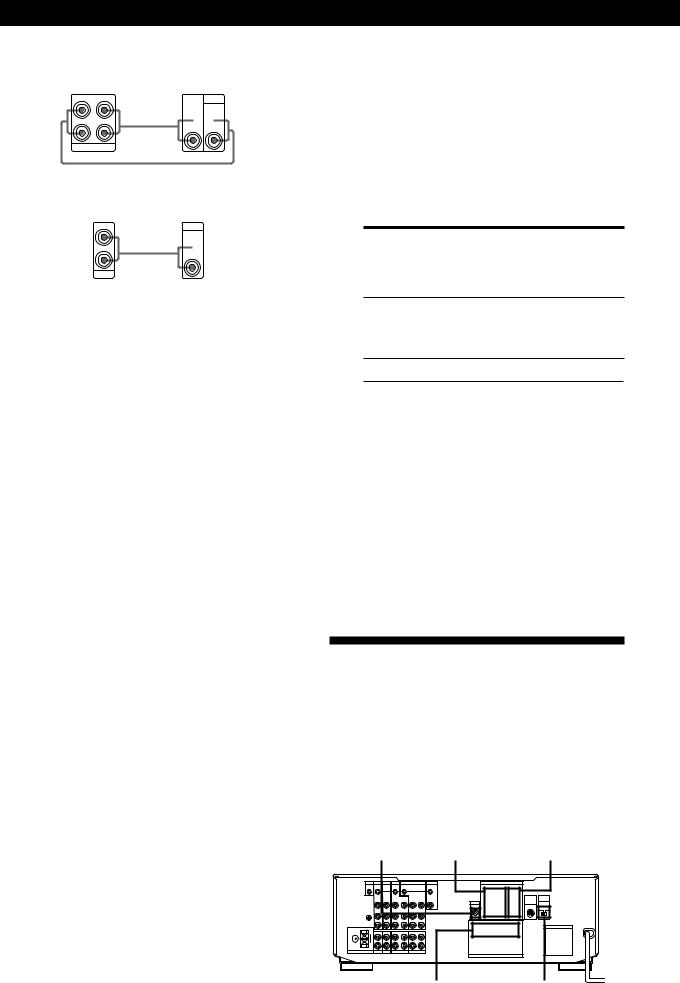
What cords will I need?
Audio cords (not supplied) (1 for each CD player and turntable; 2 for each tape deck, DAT deck, or MD deck)
White (L) |
White (L) |
Red (R) |
Red (R) |
Hookups
The arrow çindicates signal flow.
CD player
Receiver |
|
CD player |
IN |
|
OUTPUT |
L |
|
LINE |
Ç |
|
|
|
L |
|
R |
|
|
CD |
|
R |
|
|
Tape deck
Receiver |
Tape deck |
|
REC OUT IN |
OUTPUT |
INPUT |
L |
LINE |
LINE |
|
|
|
Ç |
L |
R |
|
TAPE |
R |
|
ç
(Continued) 5
Getting Started
DAT deck or MD deck
Receiver |
DAT deck or MD deck |
|
REC OUT IN |
OUTPUT |
INPUT |
L |
LINE |
LINE |
|
|
|
Ç 
 L
L
R
R
DAT/MD
ç
Turntable
Receiver Turntable
IN |
OUTPUT |
L |
LINE |
Ç  L
L
R
R
PHONO
If your turntable has an earth lead
To prevent hum, connect the earth lead to the y SIGNAL GND terminal on the receiver.
CONTROL A1 Hookups (STR-DE915/DE715 (USA, Canada) only)
•If you have a CONTROL A1 compatible Sony CD player, tape deck, or MD deck
Use a CONTROL A1 cord (not supplied) to connect the S-LINK CTRL A1 jack on the CD player, tape deck, or MD deck to the S-LINK CTRL A1 jack on the receiver. Refer the separate manual “CONTROL-A1 Control System” and the Operating Instructions supplied with your CD player, tape deck, or MD deck for details.
•If you have a Sony CD changer with a COMMAND MODE selector
If the CD changer’s COMMAND MODE selector can be switched between CD 1, CD 2, and CD 3, be sure to set the command mode to “CD 1” and connect the changer to the CD jacks on the receiver.
However, if you have a Sony CD changer with VIDEO OUT jacks, set the command mode to “CD 2” and connect the changer to the VIDEO 2 jacks on the receiver.
zYou can display the operating status of the component connected to the S-LINK CTRL A1 jack (STR-DE915/DE715 (USA, Canada) only)
1Press SET UP repeatedly to select OTHER SETUP (STR-DE915 only) or DISPLAY SETUP (STR-DE715 only).
2Use the digital processing control buttons (  /
/  ) to select CONTROL-A1.
3Use the digital processing control buttons (  /
/  ) to select the setting you want by referring to the
following table.
To |
Select |
Display “PLAY,” “STOP,” “PAUSE,” AUTO or “REC” for about 8 seconds when
the operation switches
Display “PLAY,” “STOP,” “PAUSE,” FIX “REC,” or the contents of a disc or
track memo of a CD or MD whenever you press the DISPLAY button
Turn off the operation status display OFF
Notes
•This setting is effective only when the receiver is set to TAPE, DAT/MD, VIDEO 2, or CD (see page 12). For VIDEO 2, the CD changer command mode must be “CD 2” and the CD changer must be connected to the VIDEO 2 jacks on the receiver. For CD, the CD changer command mode must be “CD 1” and the CD changer must be connected to the CD jacks on the receiver.
•If the disc or track memo contains a character that the receiver cannot display, “.” appears for that character.
•When the Mega Control function of the CD player is active, the operating status of the main player is displayed.
Speaker System Hookups
Overview
This section describes how to connect your speakers to the receiver. Although front (left and right) speakers are required, center and rear speakers are optional. Adding center and rear speakers will enhance the surround effects. Connecting an active woofer will increase bass response.
|
|
|
|
|
|
SURROUND |
SURROUND |
||
WOOFER |
SPEAKERS REAR SPEAKERS CENTER |
||||||||
|
S-LINK |
TV/DBS LD/DVD VIDEO 2 |
|
VIDEO 1 |
|
MONITOR |
SURROUND SPEAKERS |
||
|
CTRL A1 |
CTRL S |
|
CTRL S |
CTRL S |
|
|
CTRL S |
|
|
|
STATUS IN |
|
OUT |
OUT |
|
|
IN |
|
|
|
|
|
|
|
S-LINK |
|
|
|
|
|
VIDEO |
VIDEO VIDEO |
VIDEO |
VIDEO |
VIDEO |
VIDEO |
WIRELESS IMPEDANCE |
|
|
|
IN |
IN |
OUT |
IN |
OUT |
IN |
OUT |
REAR SELECTOR |
|
|
|
|
|
|
|
|
WOOFER |
SPEAKER |
|
|
|
|
|
|
|
|
FRONT |
|
|
|
|
|
|
|
|
|
AUDIO |
|
|
|
AUDIO |
AUDIO AUDIO |
AUDIO |
AUDIO |
AUDIO |
OUT |
4 Ω 8 Ω |
|
|
SIGNAL |
IN |
IN |
OUT |
IN |
OUT |
IN |
|
|
|
GND |
|
|
|
|
|
|
|
|
|
|
|
|
|
|
|
|
L |
|
|
y |
|
|
|
|
|
|
R |
AC OUTLET |
|
|
|
|
|
|
|
|
||
|
AM |
IN |
IN |
REC OUT |
IN |
REC OUT |
IN |
|
|
|
|
|
|
|
|
|
|
L |
|
FM |
y |
|
|
|
|
|
|
R |
|
75Ω |
|
|
|
|
|
|
|
||
COAXIAL |
|
|
|
|
|
|
|
|
|
ANTENNA |
|
PHONO |
CD |
DAT / MD |
TAPE |
|
|
||
FRONT SPEAKERS
6 |
FRONT SPEAKERS A |
IMPEDANCE SELECTOR |
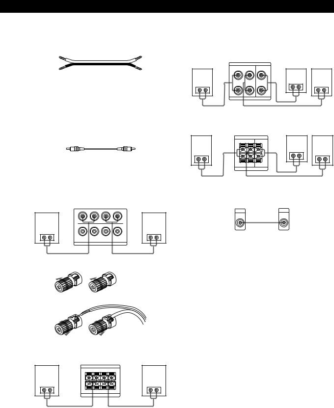
What cords will I need?
• Speaker cord (not supplied) (1 for each speaker)
(+) |
(+) |
(–) |
(–) |
Twist the stripped ends of the cord about 2/3 inch (15 mm). Be sure to match the speaker cord to the appropriate terminal on the components: + to + and – to –. If the cords are reversed, the sound will be distorted and will lack bass.
•Monaural audio cord (not supplied) (1 for an active woofer)
Black |
Black |
Hookups
Front speakers
■ STR-DE915
Front speaker |
|
Receiver |
|
Front speaker |
(R) |
|
|
(L) |
|
+ |
– – |
+ |
||
|
A |
|
A |
|
}] |
R + |
– – |
+ L |
}] |
B |
|
B |
||
|
|
IMPEDANCE USE 4–16 Ω |
|
|
|
|
FRONT SPEAKERS |
|
|
To connect the speaker cords
|
] |
|
|
|
} |
|
|
à |
|
|
|
|
|
|
] |
|
|
|
} |
|
■ STR-DE715/DE615/D660Z/D560Z |
||||||
Front speaker |
|
|
|
|
|
Front speaker |
(R) |
Receiver |
(L) |
||||
|
FRONT SPEAKERS |
|||||
|
+ |
R |
– |
– |
L |
+ |
|
A |
|
|
|
|
A |
}] |
|
|
|
|
|
}] |
|
B |
|
|
|
|
B |
|
+ |
R |
– |
– |
L |
+ |
|
IMPEDANCE USE 4–16 Ω |
|||||
|
|
Getting Started |
|
Rear and center speakers |
|
|
|
■ STR-DE915 |
|
|
|
Rear speaker |
Receiver |
|
Rear speaker |
(R) |
SURROUND SPEAKERS |
Center speaker (L) |
|
|
R REAR L CENTER |
|
|
|
+ |
+ |
|
}] |
|
}] |
}] |
|
|
||
––
IMPEDANCE USE 8–16 Ω
■ STR-DE715/DE615/D660Z/D560Z |
|
||
Rear speaker |
|
|
Rear speaker |
(R) |
Receiver |
Center speaker (L) |
|
SURROUND SPEAKERS |
|
|
|
|
R REAR L CENTER |
|
|
+ |
+ |
}] |
|
}] |
|
}] |
|
|
|
||
– |
– |
|
|
|
R L |
|
|
|
IMPEDANCE USE 8–16 Ω |
|
|
Active woofer
Receiver |
Active woofer |
WOOFER |
INPUT |
AUDIO |
|
OUT |
ç |
Wireless rear speaker (STR-DE915/DE715/DE615 only)
When using an optional Sony wireless rear speaker system, connect the transmitter to the WIRELESS REAR SPEAKER jack.
Note
Do not connect any other component to the WIRELESS REAR SPEAKER jack.
zIf you have an additional front speaker system
Connect them to the FRONT SPEAKERS B terminals.
Note
If you use front speakers with low maximum power input, adjust the volume carefully to avoid excessive output on the speakers.
7
Getting Started
Speaker placement for STR-DE915
For the best possible surround sound, we recommend:
•The best quality speakers possible
•Front, center, and rear speakers of equivalent size and quality
•Positioning of speakers at the same distance from the listening position (A).
The center speaker, however, may be moved closer, but not beyond the straight line connecting the two front speakers (B). The rear speakers may also be closer to listening position than the front speakers (C), to suit the configuration of your room. If the surround effect is still inadequate, adjust the CENTER DELAY and REAR DELAY parameters (see page 19).
|
B |
|
A 45°A |
C |
C |
|
90° |
|
20° |
Notes
•Do not place the center or rear speakers farther away from the listening position than the front speakers.
•When mounting the rear speakers on side walls perpendicular to the listening position they should be placed 60 - 90 cm above the listening position (as shown below in “Speaker placement for STR-DE715/DE615/ D660Z/D560Z”).
Depending on the shape of your room (etc.), you may wish to place the rear speakers behind you instead of on the side walls. One advantage of this placement is that you can use a pair of large floor standing speakers matching your front speakers.
|
B |
|
A 45°A |
C |
C |
|
90° |
|
20° |
Note
If you place the rear speakers behind you, be sure to check the speaker location setting in the SPEAKER SETUP menu when using VIRTUAL MULTI REAR and VIRTUAL REAR SHIFT sound fields (see pages 19 and 24 for details).
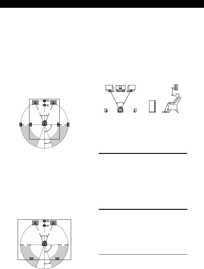
Speaker placement for STR-DE715/DE615/ D660Z/D560Z
For optimum surround sound effect, place your speakers as shown below.
Rear speaker
|
60 - 90 cm |
45° |
Front speaker |
|
Selecting the impedance
Set the IMPEDANCE SELECTOR for the front speakers as indicated in the table below. Check the instruction manual of your speakers if you’re not sure of the impedance. (This information is usually printed on a label on the back of the speaker.)
If nominal impedance of |
Set IMPEDANCE SELECTOR to |
your speaker is |
|
|
|
Between 4 and 8 ohms |
4 Ω |
|
|
8 ohms or higher |
8 Ω |
|
|
Selecting the speaker system
If you connect only one set of front speakers, set the SPEAKERS selector on the front panel to A. If you connect two sets of front speakers, see the following:
To drive |
Set SPEAKERS selector to |
|
|
Speaker system A (connected |
A |
to the FRONT SPEAKERS A |
|
terminals) |
|
|
|
Speaker system B (connected |
B |
to the FRONT SPEAKERS B |
|
terminals) |
|
|
|
Both speaker systems A and B |
A+B* |
(parallel connection) |
|
* Do not use A+B with SOUND FIELD set to ON.
8

Getting Started
TV/VCR Hookups
Overview
This section describes how to connect video components to the receiver.
Note for STR-DE915
For digital connections, see “Digital Component Hookups (STR-DE915 only)” on page 10.
LD/DVD (STR-DE915 only)
|
|
|
|
VIDEO 1 |
|
|
||||
|
S-LINK |
TV/DBS LD/DVD VIDEO 2 |
|
VIDEO 1 |
|
MONITOR |
SURROUND SPEAKERS |
|
||
|
CTRL A1 |
CTRL S |
|
CTRL S |
CTRL S |
|
|
CTRL S |
|
|
|
|
STATUS IN |
|
OUT |
OUT |
|
|
IN |
|
|
|
|
|
|
|
|
S-LINK |
|
|
|
|
|
|
VIDEO |
VIDEO |
VIDEO |
VIDEO |
VIDEO |
VIDEO |
VIDEO |
WIRELESS |
IMPEDANCE |
|
|
IN |
IN |
OUT |
IN |
OUT |
IN |
OUT |
REAR |
SELECTOR |
|
|
|
|
|
|
|
|
WOOFER |
SPEAKER |
FRONT |
|
|
|
|
|
|
|
|
|
||
|
|
|
|
|
|
|
|
AUDIO |
|
|
|
|
AUDIO |
AUDIO |
AUDIO |
AUDIO |
AUDIO |
AUDIO |
OUT |
|
4 Ω 8 Ω |
|
SIGNAL |
IN |
IN |
OUT |
IN |
OUT |
IN |
|
|
|
|
GND |
|
|
|
|
|
|
|
|
|
|
|
|
|
|
|
|
|
L |
|
|
|
y |
|
|
|
|
|
|
R |
|
AC OUTLET |
|
|
|
|
|
|
|
|
|
||
|
AM |
IN |
IN |
REC OUT |
IN |
REC OUT |
IN |
|
|
|
|
|
|
|
|
|
|
|
L |
|
|
FM |
y |
|
|
|
|
|
|
R |
|
|
75Ω |
|
|
|
|
|
|
|
|
||
COAXIAL |
|
|
|
|
|
|
|
|
|
|
ANTENNA |
|
PHONO |
CD |
DAT / MD |
TAPE |
|
|
|
||
FRONT SPEAKERS
TV/DBS* VIDEO 2 MONITOR
*TV/DBS: USA, Canadian, and Australian models TV: other models
What cables will I need?
•Audio/video cable (supplied with STR-DE715 (USA, Canada) only) (1 for each TV or LD player; 2 for each VCR)
Yellow |
Yellow |
White (L) 
 White (L)
Red (R) |
Red (R) |
• Video cable (not supplied) (1 for a TV monitor)
Yellow |
Yellow |
Hookups
The arrow çindicates signal flow.
TV or Digital Broadcasting System (DBS) tuner
DBS tuners can be used with the USA, Canadian, and Australian models.
Receiver |
TV or DBS tuner |
|
TV/DBS |
|
OUTPUT |
VIDEO |
|
|
IN |
|
VIDEO |
|
|
|
AUDIO |
Ç |
AUDIO |
IN |
||
L |
|
L |
R |
|
R |
TV monitor
If you use a TV monitor, do not connect anything to the TV/ DBS VIDEO IN jack.
Receiver |
TV monitor |
|
MONITOR |
INPUT |
|
VIDEO |
||
VIDEO |
||
OUT |
||
|
ç
VCR (via the VIDEO 1/2 jacks)
If you have two VCRs, connect the second one to the VIDEO 2 jacks.
Receiver |
VCR |
||
VIDEO 1 |
OUTPUT |
INPUT |
|
VIDEO |
VIDEO |
|
|
OUT |
IN |
VIDEO |
VIDEO |
|
|
||
AUDIO |
AUDIO |
Ç AUDIO |
AUDIO |
OUT |
IN |
||
L |
|
|
L |
R |
|
|
R |
ç
Video camera recorder or video game (STR-DE915 only)
Use the VIDEO 3 INPUT jacks on the front panel.
|
Video camera recorder or |
|
|
|
video game |
Receiver |
|
OUTPUT |
|
VIDEO |
|
VIDEO 3 INPUT |
|
|
VIDEO L AUDIO R |
Ç |
AUDIO |
|
|
L |
R
LD or DVD player (STR-DE915 only)
If you have an additional LD or DVD player, connect it to the VIDEO 2 jacks.
Receiver |
LD or DVD player |
|
LD/DVD |
|
OUTPUT |
VIDEO |
|
|
|
|
|
IN |
|
VIDEO |
|
|
|
AUDIO |
Ç |
AUDIO |
IN |
||
L |
|
L |
R |
|
R |
LD player (via the VIDEO 2 jacks) (STR-DE715/DE615/ D660Z/D560Z only)
Receiver |
LD player |
|
VIDEO 2 |
OUTPUT |
|
VIDEO |
VIDEO |
|
OUT |
IN |
VIDEO |
|
|
|
AUDIO |
AUDIO |
Ç AUDIO |
OUT |
IN |
|
L |
|
L |
R |
|
R |
(Continued)
9

Getting Started
zYou can play decoded Dolby Digital AC-3 soundtracks through the speakers connected to the receiver (STR-DE715/DE615/D660Z/D560Z only)
If you have a Dolby Digital (AC-3) decoder, you can use the receiver to amplify a decoded Dolby Digital AC-3 soundtrack with the following connections. Refer to the instruction manual supplied with your Dolby Digital (AC-3) decoder.
Dolby Digital (AC-3) |
DVD player or |
|||
decoder etc. |
Receiver |
LD player etc. |
||
ç |
||||
PRE OUT |
FRONT REAR |
|
|
OUTPUT |
REAR |
FRONT |
VIDEO |
|
|
|
L |
IN |
|
VIDEO |
CENTER |
ç |
|
Ç |
|
|
|
|||
|
|
|
|
|
|
R |
|
|
|
WOOFER |
|
|
|
AUDIO |
|
ç |
|
|
|
|
|
|
L |
|
|
CENTER WOOFER |
|
|
|
|
ç 5.1 INPUT |
|
|
R |
If you have a CONTROL S compatible Sony TV, DBS tuner, monitor, VCR or LD player (STR-DE915/DE715 (USA, Canada) only)
Use a CONTROL S cord (supplied) to connect the CTRL S (STATUS) IN (for TV, DBS tuner, or monitor) or OUT (for VCR or LD player (STR-DE715 (USA, Canada) only)) jack on the receiver to the appropriate S-LINK jack on the respective component. Refer to the Operating Instructions supplied with your TV, DBS tuner, monitor, VCR, or LD player for details.
Digital Component Hookups (STR-DE915 only)
Overview
This section describes how to connect a LD/DVD player, DAT/MD decks, and CD player equipped with digital jack(s) to the STR-DE915. If you use a digital component, select the appropriate input mode for the component (see page 12).
LD/DVD IN AC-3 RF/OPTICAL
LD / DVD IN |
|
|
|
|
|
|
|
|
|
|
|
|
|
AC-3 |
S-LINK |
TV/DBS LD/DVD VIDEO 2 |
|
VIDEO 1 |
|
MONITOR |
|
SURROUND SPEAKERS |
|
|
|||
RF |
CTRL A1 |
CTRL S |
|
CTRL S |
CTRL S |
|
|
CTRL S |
|
R REAR L |
CENTER |
|
|
LD / DVD IN |
|
STATUS IN |
|
OUT |
OUT |
|
|
IN |
|
|
|
||
|
|
|
|
|
S-LINK |
|
|
|
|
|
|
|
|
OPTICAL |
|
|
|
|
|
|
|
|
|
|
|
|
|
CD IN |
|
VIDEO |
VIDEO |
VIDEO |
VIDEO |
VIDEO |
VIDEO |
VIDEO |
+ |
|
+ |
WIRELESS |
IMPEDANCE |
|
|
IN |
IN |
OUT |
IN |
OUT |
IN |
OUT |
|
|
|
REAR |
SELECTOR |
OPTICAL |
|
|
|
|
|
|
|
WOOFER |
|
|
|
SPEAKER |
FRONT |
DAT / MD IN |
|
|
|
|
|
|
|
AUDIO |
– |
|
– |
|
|
OPTICAL |
|
AUDIO |
AUDIO |
AUDIO |
AUDIO |
AUDIO |
AUDIO |
OUT |
|
|
|
|
4 Ω 8 Ω |
|
SIGNAL |
IN |
IN |
OUT |
IN |
OUT |
IN |
|
|
|
|
|
|
DAT / MD OUT |
GND |
|
|
|
|
|
|
|
|
|
|
|
|
|
|
|
|
|
|
|
L |
|
IMPEDANCE USE 8–16 |
Ω |
|
OPTICAL |
|
|
|
|
|
|
|
|
|
||
|
y |
|
|
|
|
|
|
+ |
– – |
+ |
|
DIGITAL |
|
|
|
|
|
R |
|
|
|
AC OUTLET |
|
|
|
|
|
|
|
A |
|
A |
|||
|
|
|
|
|
|
|
|
|
SWITCHED 120W / 1A MAX |
||
|
AM |
IN |
IN |
REC OUT |
IN |
REC OUT |
IN |
|
|
|
|
|
|
|
|
|
|
|
L |
R + |
– – |
+ L |
|
FM |
y |
|
|
|
|
|
R |
B |
|
B |
|
75Ω |
|
|
|
|
|
|
|
|
|
||
COAXIAL |
|
|
|
|
|
|
|
|
|
|
|
ANTENNA |
|
PHONO |
CD |
DAT / MD |
TAPE |
|
|
IMPEDANCE USE 4–16 Ω |
|
AC 120V 60Hz |
|
|
|
|
|
|
|
|
|
|
|
||
|
|
|
|
|
|
|
|
|
FRONT SPEAKERS |
|
|
DAT/MD IN/OUT |
CD IN OPTICAL |
OPTICAL |
|
What cords will I need?
•Optical digital connecting cord (not supplied) (1 for a DVD, LD or CD player; 2 for a DAT or MD deck)
•Coaxial digital connecting cord (not supplied) (1 for a DVD or LD player)
Hookups
The arrow çindicates signal flow.
LD or DVD player
Receiver |
LD or DVD player |
|
LD / DVD IN |
|
DIGITAL |
AC-3 |
|
|
RF |
|
|
LD / DVD IN |
Ç |
OUT |
OPTICAL
CD IN
OPTICAL
DAT / MD IN
OPTICAL
DAT / MD OUT
OPTICAL
DIGITAL
If your LD or DVD player has an optical output jack, connect it to the LD/DVD IN OPTICAL jack. If your LD player has an RF output jack, connect it to the LD/DVD IN AC-3 RF jack of the receiver as shown below.
Receiver |
|
LD player |
LD / DVD IN |
Ç |
ACRF-3 |
AC-3 |
||
RF |
|
|
LD / DVD IN |
|
OUT |
OPTICAL
CD IN
OPTICAL
DAT / MD IN
OPTICAL
DAT / MD OUT
OPTICAL
DIGITAL
CD player
Receiver |
CD player |
|
LD / DVD IN |
DIGITAL |
|
AC-3 |
|
|
RF |
|
|
LD / DVD IN |
OUT |
|
OPTICAL |
|
|
CD IN |
Ç |
|
OPTICAL |
||
|
||
DAT / MD IN |
|
|
OPTICAL |
|
|
DAT / MD OUT |
|
|
OPTICAL |
|
|
DIGITAL |
|
10
DAT or MD deck
Receiver |
DAT or MD deck |
LD / DVD IN |
DIGITAL |
AC-3 |
|
RF |
|
LD / DVD IN |
OUT IN |
OPTICAL |
|
CD IN |
|
OPTICAL |
|
DAT / MD IN |
Ç |
OPTICAL |
|
DAT / MD OUT |
Xç |
OPTICAL |
|
DIGITAL
Warning regarding the playback of DAT/MD sources
When playing DAT/MD sources through the receiver, do not play a DAT/MD that contains digital recordings made from a DVD player whose digital output was set to “DOLBY DIGITAL.” High volume will be output which may damage the receiver and your speakers.
Notes
•You cannot connect a LD or DVD player through digital connection when the LD/DVD IN OPTICAL jack is already used. In this case, connect the LD or DVD player to the LD/DVD jacks.
•This receiver is compatible only with digital components using 32, 44.1, or 48-kHz sampling frequencies and not compatible with 96 kHz.
•Be sure to connect digital components (CD player, DAT/ MD deck, etc.) to the analog jacks as well as the digital jacks in order to do analog recording.
AC Hookups
Setting the voltage selector (only on the models supplied with the voltage selector)
Check that the voltage selector on the rear panel of the receiver is set to the local power supply voltage. If not, set the selector to the correct position using a screwdriver before connecting the AC power cord to a wall outlet.
VOLTAGE SELECT
220V
240V
120V
Connecting the AC power cord
Connect the AC power cord from this receiver and from your audio/video components to a wall outlet.
If you connect other audio components to AC OUTLET on the receiver, the receiver can supply power to the connected component(s) so you can turn on/off whole system when you turn on/off the receiver. Note that only one switched AC outlet is supplied with the Australian STR-DE915/DE715.
|
|
|
|
|
|
|
|
|
Getting Started |
|
|
|
|
|
|
|
|
|
|
AC OUTLET |
|
|
S-LINK |
TV/DBS |
LD/DVD VIDEO 2 |
|
VIDEO 1 |
|
MONITOR |
SURROUND SPEAKERS |
|
|
|
CTRL A1 |
CTRL S |
|
CTRL S |
CTRL S |
|
|
CTRL S |
|
|
|
|
STATUS IN |
|
OUT |
OUT |
|
|
IN |
|
|
|
|
|
|
|
|
S-LINK |
|
|
|
|
|
|
VIDEO |
VIDEO |
VIDEO |
VIDEO |
VIDEO |
VIDEO |
VIDEO |
WIRELESS |
IMPEDANCE |
|
|
IN |
IN |
OUT |
IN |
OUT |
IN |
OUT |
REAR |
SELECTOR |
|
|
|
|
|
|
|
|
WOOFER |
SPEAKER |
FRONT |
|
|
|
|
|
|
|
|
AUDIO |
|
|
|
|
AUDIO |
AUDIO |
AUDIO |
AUDIO |
AUDIO |
AUDIO |
OUT |
|
4 Ω 8 Ω |
|
SIGNAL |
|
|
|
||||||
|
IN |
IN |
OUT |
IN |
OUT |
IN |
|
|
|
|
|
GND |
|
|
|
|
|
|
|
|
|
|
|
|
|
|
|
|
|
L |
|
|
|
y |
|
|
|
|
|
|
R |
|
AC OUTLET |
|
|
|
|
|
|
|
|
|
||
|
AM |
IN |
IN |
REC OUT |
IN |
REC OUT |
IN |
|
|
|
|
|
|
|
|
|
|
|
L |
|
|
FM |
y |
|
|
|
|
|
|
R |
|
|
75Ω |
|
|
|
|
|
|
|
|
||
COAXIAL |
|
|
|
|
|
|
|
|
|
|
ANTENNA |
|
PHONO |
CD |
DAT / MD |
TAPE |
|
|
|
||
FRONT SPEAKERS
b
to a wall outlet
Caution
Make sure that the total power consumption of the component(s) connected to receiver’s AC OUTLET does not exceed the wattage stated on the rear panel. Do not connect high-wattage electrical home appliances such as electric irons, fans, or TVs to this outlet.
Before You Use Your Receiver
Before you start using your receiver, make sure that you have:
•Turned MASTER VOLUME to the leftmost position
(0).
•Selected the appropriate speaker system. (For details, see “Selecting the speaker system” on page 8.)
•Set BALANCE to the center position.
Turn on the receiver and check the following indicator.
•Press MUTING on the remote if “MUTING” appears in the display.
Clearing the receiver’s memory
Before you use your receiver for the first time or when you want to clear the receiver’s memory, do the procedure below.
POWER |
|
|
|
|
|
|
AUDIO FUNCTION |
|
|
|
|
|
|
|
|
|
|
||||
|
|
|
|
|
|
|
|
|
|
|
|
|
|
MASTER VOLUME |
|
|
|
|
|||
|
|
|
|
|
|
|
|
|
|
|
|
|
|
• • |
• 5 |
• |
• • |
|
|
|
|
POWER |
TONE |
|
|
|
|
|
|
|
|
|
|
• |
4 |
|
|
|
|
6 |
• |
|
|
|
|
|
|
|
|
|
|
|
|
|
|
|
|
|
|
|
|
• |
|
|
|
SUR |
INDEX |
VIDEO 1 |
|
VIDEO 2 |
|
VIDEO 3 LD / DVD TV/DBS |
TAPE DAT / MD |
CD |
TUNER |
PHONO |
• |
|
|
|
|
|
|
|
• |
|
|
|
|
|
|
|
3 |
|
|
|
|
|
|
|
|
7 |
|||||||
|
|
|
|
|
|
|
|
|
|
|
|
• |
|
|
|
|
|
|
|
|
• |
|
|
|
|
|
|
|
|
|
|
|
|
• |
|
|
|
|
|
|
|
|
• |
DPC |
|
|
|
|
|
|
|
|
|
|
|
• |
|
|
|
|
|
|
|
|
• |
MODE |
|
|
|
|
|
|
|
|
|
|
|
2 |
|
|
|
|
|
|
|
|
8 |
|
|
|
|
|
|
|
|
|
|
|
|
• |
|
|
|
|
|
|
|
|
• |
|
|
|
|
|
|
|
|
|
|
|
|
• |
|
|
|
|
|
|
|
|
• |
|
|
|
|
|
|
|
|
|
|
|
DIRECT PASS |
• |
|
|
|
|
|
|
|
|
• |
|
|
|
|
|
|
|
|
|
|
|
|
1 |
|
|
|
|
|
|
|
|
9 |
SPEAKERS |
|
g |
|
|
|
|
|
|
|
|
DISCRETE |
• |
|
|
|
|
|
|
|
• |
|
|
|
|
|
|
|
|
|
|
• |
|
|
|
|
|
|
|
|
|
|||
OFF A B |
|
|
|
|
|
|
|
|
|
|
• |
0 |
|
|
|
|
10 |
• |
• |
BALANCE |
|
A+B |
|
|
|
|
|
|
|
|
|
|
|
BASS |
|
|
|
|
|
||||
|
|
|
|
|
|
|
|
DIRECT |
|
SOUND FIELD |
BOOST |
|
|
|
|
|
|
|
|
|
|
TUNING |
PRESET |
1 |
2 |
3 |
4 |
5 |
DIRECT |
|
PASS SET UP |
ON / OFF |
|
|
|
|
|
|
|
|
|
|
|
TUNING |
|
|
|
|
|
|
|
|
|
|
|
|
|
|
|||||||
– + |
– |
+ |
|
|
|
|
VIDEO FUNCTION |
AUDIO FUNCTION |
INPUT |
GENRE MODE |
|
|
|
|
|
|
|
|
|
|
|
|
|
|
|
|
|
|
MODE |
|
|
|
|
|
|
|
|
|
L |
|
R |
||
PHONES |
|
6 |
7 |
8 |
9 |
0 |
SHIFT |
|
|
|
|
|
|
|
|
|
|
|
|
|
|
FM MODE FM / AM DISPLAY MEMORY |
|
|
|
|
|
|
|
|
|
VIDEO 3 INPUT |
|
|
|
|
|
|
|
|
|||
|
|
|
|
|
|
|
|
|
|
|
|
|
|
VIDEO |
|
L AUDIO |
R |
|
|||
|
|
VIDEO FUNCTION |
|
MODE |
|
|
|
|
|
|
|
|
|
|
|||||||
1 Turn off the receiver. |
|
|
|
|
|
|
|
|
|
|
|
|
|
|
|||||||
2 Press down VIDEO FUNCTION |
, AUDIO |
||||||||||||||||||||
FUNCTION |
|
, MODE, and POWER |
|
|
|
|
|
|
|
|
|
||||||||||
simultaneously. |
|
|
|
|
|
|
|
|
|
|
|
|
|
|
|||||||
The contents of the memory (preset station |
|
|
|
||||||||||||||||||
and other parameter settings) are erased. |
|
|
|
|
|
11 |
|||||||||||||||
|
|
|
|
|
|
|
|
|
|
|
|
|
|
|
|
|
|
|
|
|
|

Receiver Operations
Selecting a Component
To listen to or watch a connected component, first select the function on the receiver or with the remote. Before you begin, make sure you have:
•Connected all components securely and correctly as indicated on pages 4 to 11.
•Turned MASTER VOLUME to the leftmost position
(0)to avoid damaging your speakers.
Digital processing control buttons
POWER |
|
|
|
|
DIRECT PASS |
SET UP MASTER VOLUME |
||||||||||||||||||
|
|
|
|
|
|
|
|
|
|
|
|
|
|
|
|
MASTER VOLUME |
|
|
|
|||||
|
|
|
|
|
|
|
|
|
|
|
|
|
|
|
|
• • |
• |
5 |
• |
• |
• |
|
|
|
POWER |
|
|
|
|
|
|
|
|
|
|
|
|
|
|
4 |
|
|
|
6 • |
|
|
|||
|
TONE |
|
|
|
|
|
|
|
|
|
|
|
• |
|
|
|
|
|
|
|
|
|||
|
|
|
|
|
|
|
|
|
|
|
|
|
|
|
|
|
|
|
|
|
• |
|
|
|
SUR |
|
INDEX |
VIDEO 1 |
|
VIDEO 2 |
|
VIDEO 3 LD / DVD TV/DBS |
TAPE |
DAT / MD |
CD |
TUNER |
PHONO |
• |
|
|
|
|
|
|
|
|
• |
|
|
|
|
|
|
|
|
3 |
|
|
|
|
|
|
|
|
|
7 |
||||||||
|
|
|
|
|
|
|
|
|
|
|
|
|
|
• |
|
|
|
|
|
|
|
|
|
• |
|
|
|
|
|
|
|
|
|
|
|
|
|
|
• |
|
|
|
|
|
|
|
|
|
• |
DPC |
|
|
|
|
|
|
|
|
|
|
|
|
|
• |
|
|
|
|
|
|
|
|
|
• |
MODE |
|
|
|
|
|
|
|
|
|
|
|
|
|
2 |
|
|
|
|
|
|
|
|
|
8 |
|
|
|
|
|
|
|
|
|
|
|
|
|
|
• |
|
|
|
|
|
|
|
|
|
• |
|
|
|
|
|
|
|
|
|
|
|
|
|
|
• |
|
|
|
|
|
|
|
|
|
• |
|
|
|
|
|
|
|
|
|
|
|
|
DIRECT PASS |
• |
|
|
|
|
|
|
|
|
|
• |
|
|
|
|
|
|
|
|
|
|
|
|
|
|
|
1 |
|
|
|
|
|
|
|
|
|
9 |
SPEAKERS |
|
|
g |
|
|
|
|
|
|
|
|
|
DISCRETE |
• |
|
|
|
|
|
|
|
|
• |
|
|
|
|
|
|
|
|
|
|
|
|
• |
|
|
|
|
|
|
|
|
|
|
|||
OFF A B |
|
|
|
|
|
|
|
|
|
|
|
|
• |
0 |
|
|
|
|
|
|
• |
• |
BALANCE |
|
A+B |
|
|
|
|
|
|
|
|
|
|
|
|
|
BASS |
|
|
|
|
|
|
10 |
|||
|
|
|
|
|
|
|
|
|
|
DIRECT |
|
SOUND FIELD |
BOOST |
|
|
|
|
|
|
|
|
|
|
|
TUNING |
|
PRESET |
1 |
2 |
3 |
4 |
5 |
DIRECT |
|
|
PASS SET UP |
|
ON / OFF |
|
|
|
|
|
|
|
|
|
|
|
– |
+ |
– |
+ |
|
|
|
|
VIDEO FUNCTION |
AUDIO FUNCTION |
INPUT |
GENRE MODE |
|
|
|
|
|
|
|
|
|
|
|
|
|
|
|
|
|
|
|
|
0 |
MODE |
|
|
|
|
|
|
|
|
|
|
L |
|
R |
|||
PHONES |
|
|
6 |
7 |
8 |
9 |
SHIFT |
|
|
|
|
|
|
|
|
|
|
|
|
|
|
|
|
|
FM MODE FM / AM DISPLAY MEMORY |
|
|
|
|
|
|
|
|
|
|
VIDEO 3 INPUT |
|
|
|
|
|
|
|
|
|
||||
|
|
|
|
|
|
|
|
|
|
|
|
|
|
|
|
VIDEO |
|
|
|
L |
AUDIO |
R |
|
|
|
|
|
|
|
|
VIDEO/AUDIO |
|
|
|
|
|
|
|
|
|
|
|
|
|
|
|
|||
PHONES |
|
|
|
|
FUNCTION |
|
INPUT |
|
BASS |
|
|
|
|
BALANCE |
||||||||||
SPEAKERS |
|
|
|
MODE |
|
BOOST |
|
|
|
|
|
|||||||||||||
1Press POWER to turn on the receiver.
2Select the component you want to use:
To watch or |
Press |
To light up |
listen to |
(repeatedly) |
|
|
|
|
Video tapes |
VIDEO |
VIDEO 1 or VIDEO 2 |
|
FUNCTION |
|
|
|
|
Video camera |
VIDEO |
VIDEO 3 |
recorder or video |
FUNCTION |
|
game (STR-DE915 |
|
|
only) |
|
|
|
|
|
Laser discs |
VIDEO |
LD/DVD (STR- |
|
FUNCTION |
DE915 only) or |
|
|
VIDEO 2 (STR- |
|
|
DE715/DE615/ |
|
|
D660Z/D560Z only) |
|
|
|
DVD (STR-DE915 |
VIDEO |
LD/DVD |
only) |
FUNCTION |
|
|
|
|
TV programs |
VIDEO |
TV/DBS* (STR- |
|
FUNCTION |
DE915 (USA, Canada, |
|
|
and Australia)/ |
|
|
DE715/DE615/ |
|
|
D660Z/D560Z only) |
|
|
or TV (STR-DE915 |
|
|
(for all other |
|
|
countries) only) |
|
|
|
Audio tapes |
AUDIO |
TAPE |
|
FUNCTION |
|
|
|
|
Digital Audio Tapes |
AUDIO |
DAT/MD |
(DAT) or MiniDiscs |
FUNCTION |
|
(MD) |
|
|
To watch or |
Press |
To light up |
listen to |
(repeatedly) |
|
|
|
|
Compact Discs (CD) AUDIO |
CD |
|
|
FUNCTION |
|
|
|
|
Radio programs |
AUDIO |
TUNER |
|
FUNCTION |
|
|
|
|
Records |
AUDIO |
PHONO |
|
FUNCTION |
|
*DBS tuners can be used with the USA, Canadian, and Australian models.
3Turn on the component, for example, a CD player, and then start playing.
To tune in radio stations on this receiver, see “Receiving Broadcasts” on page 15.
4Turn MASTER VOLUME to adjust the volume. To adjust the volume of the TV’s speakers, use the volume control on the TV.
zTo listen to digital program sources (STR-DE915 only)
Do the procedure below.
1 Do Steps 1 and 2 above to select the component.
2 Press INPUT MODE repeatedly to select input mode for the component.
When you select |
The receiver selects |
|
|
|
|
AUTO INPUT |
the component connected to the |
|
|
following jack(s) (listed in order |
|
|
of priority): |
|
|
1 |
the LD/DVD IN AC-3 RF jack* |
|
2 |
the OPTICAL jack |
|
3 |
the analog jacks |
|
|
|
DIGITAL (AC-3 RF) the component connected to the (appears only when LD/DVD IN AC-3 RF jack
you selected LD/ DVD in Step 1)
DIGITAL(OPTICAL) |
the component connected to the |
|
OPTICAL jack |
|
|
ANALOG INPUT |
the component connected to the |
|
analog jacks |
* Only when you selected LD/DVD in Step 1
To play the decoded Dolby Digital AC-3 program source connected to the 5.1 INPUT jacks (STRDE715/DE615/D660Z/D560Z only)
Press 5.1/DVD INPUT so that the 5.1 INPUT indicator lights up.
12
 Loading...