


STR-DH810

Multi Channel AV
Receiver
4-168-075-11(1)
Operating Instructions
STR-DH810
©2010 Sony Corporation
WARNING
To reduce the risk of fire or electric
shock, do not expose this apparatus to
rain or moisture.
To reduce the risk of fire, do not cover the
ventilation opening of the apparatus with
newspapers, tablecloths, curtains, etc. Do not place
the naked flame sources such as lighted candles on
the apparatus.
Do not install the appliance in a confined space, such
as a bookcase or built-in cabinet.
To reduce the risk of fire or electric shock, do not
expose this apparatus to dripping or splashing, and
do not place objects filled with liquids, such as
vases, on the apparatus.
As the main plug is used to disconnect the unit from
the mains, connect the unit to an easily accessible
AC outlet. Should you notice an abnormality in the
unit, disconnect the main plug from the AC outlet
immediately.
Do not expose batteries or apparatus with batteryinstalled to excessive heat such as sunshine, fire or
the like.
The unit is not disconnected from the mains as long
as it is connected to the AC outlet, even if the unit
itself has been turned off.
Excessive sound pressure from earphones and
headphones can cause hearing loss.
This symbol is intended to alert
the user to the presence of the Hot
Surface that may be hot if it is
touched during the normal
operation.
For customers in the United
States
Owner’s Record
The model and serial numbers are located on the rear
of the unit. Record these numbers in the space
provided below. Refer to them whenever you call
upon your Sony dealer regarding this product.
Model No.
Serial No.
This symbol is intended to alert the
user to the presence of uninsulated
“dangerous voltage” within the
product’s enclosure that may be of
sufficient magnitude to constitute a
risk of electric shock to persons.
This symbol is intended to alert the
user to the presence of important
operating and maintenance
(servicing) instructions in the
literature accompanying the
appliance.
Important Safety Instructions
1) Read these instructions.
2) Keep these instructions.
3) Heed all warnings.
4) Follow all instructions.
5) Do not use this apparatus near water.
6) Clean only with dry cloth.
7) Do not block any ventilation openings. Install in
accordance with the manufacturer’s instructions.
8) Do not install near any heat sources such as
radiators, heat registers, stoves, or other
apparatus (including amplifiers) that produce
heat.
9) Do not defeat the safety purpose of the polarized
or grounding-type plug. A polarized plug has
two blades with one wider than the other. A
grounding type plug has two blades and a third
grounding prong. The wide blade or the third
prong are provided for your safety. If the
provided plug does not fit into your outlet,
consult an electrician for replacement of the
obsolete outlet.
10)Protect the power cord from being walked on or
pinched particularly at plugs, convenience
receptacles, and the point where they exit from
the apparatus.
11)Only use attachments/accessories specified by
the manufacturer.
12)Use only with the cart, stand, tripod, bracket, or
table specified by the manufacturer, or sold with
the apparatus. When a cart is used, use caution
when moving the cart/apparatus combination to
avoid injury from tip-over.
GB
2

13)Unplug this apparatus during lightning storms or
when unused for long periods of time.
14)Refer all servicing to qualified service personnel.
Servicing is required when the apparatus has
been damaged in any way, such as power-supply
cord or plug is damaged, liquid has been spilled
or objects have fallen into the apparatus, the
apparatus has been exposed to rain or moisture,
does not operate normally, or has been dropped.
The following FCC statement
applies only to the version of
this model manufactured for
sale in the U.S.A. Other
versions may not comply with
FCC technical regulations.
NOTE:
This equipment has been tested and found to comply
with the limits for a Class B digital device, pursuant
to Part 15 of the FCC Rules. These limits are
designed to provide reasonable protection against
harmful interference in a residential installation.
This equipment generates, uses and can radiate radio
frequency energy and, if not installed and used in
accordance with the instructions, may cause harmful
interference to radio communications. However,
there is no guarantee that interference will not occur
in a particular installation. If this equipment does
cause harmful interference to radio or television
reception, which can be determined by turning the
equipment off and on, the user is encouraged to try
to correct the interference by one or more of the
following measures:
– Reorient or relocate the receiving antenna.
– Increase the separation between the equipment
and receiver.
– Connect the equipment into an outlet on a circuit
different from that to which the receiver is
connected.
– Consult the dealer or an experienced radio/TV
technician for help.
CAUTION
You are cautioned that any changes or modifications
not expressly approved in this manual could void
your authority to operate this equipment.
To reduce the risk of electric shock, the speaker cord
should be connected to the apparatus and the
speakers in accordance with the following
instructions.
1) Disconnect the AC power cord from the MAINS.
2) Strip 10 to 15 mm of the wire insulation of the
speaker cord.
3) Connect the speaker cord to the apparatus and
the speakers carefully so as not to touch the core
of speaker cord by hand. Also disconnect the AC
power cord from the MAINS before
disconnecting the speaker cord from the
apparatus and the speakers.
For customers in Europe
Disposal of Old Electrical &
Electronic Equipment
(Applicable in the European
Union and other European
countries with separate
collection systems)
This symbol on the product or on its packaging
indicates that this product shall not be treated as
household waste. Instead it shall be handed over to
the applicable collection point for the recycling of
electrical and electronic equipment. By ensuring this
product is disposed of correctly, you will help
prevent potential negative consequences for the
environment and human health, which could
otherwise be caused by inappropriate waste
handling of this product. The recycling of materials
will help to conserve natural resources. For more
detailed information about recycling of this product,
please contact your local Civic Office, your
household waste disposal service or the shop where
you purchased the product.
continued
GB
3

Disposal of waste batteries
(applicable in the European
Union and other European
countries with separate
collection systems)
This symbol on the battery or on the packaging
indicates that the battery provided with this product
shall not be treated as household waste.
On certain batteries this symbol might be used in
combination with a chemical symbol. The chemical
symbols for mercury (Hg) or lead (Pb) are added if
the battery contains more than 0.0005% mercury or
0.004% lead.
By ensuring these batteries are disposed of correctly,
you will help prevent potentially negative
consequences for the environment and human health
which could otherwise be caused by inappropriate
waste handling of the battery. The recycling of the
materials will help to conserve natural resources.
In case of products that for safety, performance or
data integrity reasons require a permanent
connection with an incorporated battery, this battery
should be replaced by qualified service staff only.
To ensure that the battery will be treated properly,
hand over the product at end-of-life to the applicable
collection point for the recycling of electrical and
electronic equipment.
For all other batteries, please view the section on
how to remove the battery from the product safely.
Hand the battery over to the applicable collection
point for the recycling of waste batteries.
For more detailed information about recycling of
this product or battery, please contact your local
Civic Office, your household waste disposal service
or the shop where you purchased the product.
Notice for customers: The following
information is only applicable to
equipment sold in countries applying
EU Directives.
The manufacturer of this product is Sony
Corporation, 1-7-1 Konan Minato-ku Tokyo,
108-0075 Japan. The Authorized Representative for
EMC and product safety is Sony Deutschland
GmbH, Hedelfinger Strasse 61, 70327 Stuttgart,
Germany. For any service or guarantee matters
please refer to the addresses given in separate
service or guarantee documents.
GB
4
About This Manual
B
• The instructions in this manual are for model
STR-DH810. Check your model number by
looking at the lower right corner of the front panel.
In this manual, models of area code CEL is used
for illustration purposes unless stated otherwise.
Any difference in operation is clearly indicated in
the text, for example, “Models of area code CEK
only”.
• The instructions in this manual describe the
controls on the supplied remote. You can also use
the controls on the receiver if they have the same
or similar names as those on the remote.
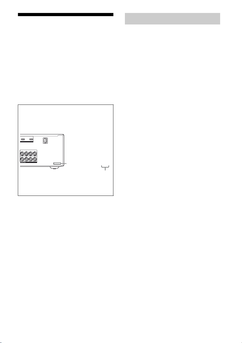
About area codes
The area code of the receiver you purchased is
shown on the lower right portion of the rear panel
(see the illustration below).
IN 1 TV OUT
ARC
LE (INPUT ONLY)
SURROUND
LR
FRONT A
LR
4-XXX-XXX-XX(X) AA
Area code
Any differences in operation, according to the area
code, are clearly indicated in the text, for example,
“Models of area code AA only”.
On Copyrights
This receiver incorporates Dolby* Digital and Pro
Logic Surround and the DTS** Digital Surround
System.
* Manufactured under license from Dolby
Laboratories. Dolby, Pro Logic, and the doubleD symbol are trademarks of Dolby Laboratories.
** Manufactured under license under U.S. Patent
#’s: 5,451,942; 5,956,674; 5,974,380; 5,978,762;
6,226,616; 6,487,535; 7,212,872; 7,333,929;
7,392,195; 7,272,567 & other U.S. and
worldwide patents issued & pending. DTS is a
registered trademark and the DTS logos, Symbol,
DTS-HD and DTS-HD Master Audio are
trademarks of DTS, Inc. © 1996-2008 DTS, Inc.
All Rights Reserved.
This receiver incorporates High-Definition
Multimedia Interface (HDMI
HDMI, the HDMI Logo, and High-Definition
Multimedia Interface are trademarks or registered
trademarks of HDMI Licensing LLC in the United
States and other countries.
“x.v.Colour (x.v.Color)” and “x.v.Colour
(x.v.Color)” logo are trademarks of Sony
Corporation.
“BRAVIA” is a trademark of Sony Corporation.
“S-AIR” and its logo are trademarks of Sony
Corporation.
TM
) technology.
“PLAYSTATION” is a trademark of Sony
Computer Entertainment Inc.
GB
5

Table of Contents
About This Manual........................................5
Supplied accessories......................................7
Description and location of parts...................8
Connections
1: Installing the speakers .............................17
2: Connecting the speakers..........................19
3: Connecting the TV ..................................21
4a: Connecting the audio components.........23
4b: Connecting the video components ........24
5: Connecting the antennas (aerials)............32
6: Inserting the wireless transmitter/
transceiver...............................................32
7: Connecting the AC power cord
(mains lead) ............................................33
Preparing the Receiver
Initializing the receiver................................34
Selecting the speaker system .......................34
Calibrating the appropriate speaker settings
automatically
(AUTO CALIBRATION).......................35
Adjusting the speaker levels
(TEST TONE) ........................................42
Basic Operations
Playback ......................................................43
Viewing information on the display ............44
Using the Sleep Timer .................................45
Recording .................................................... 45
Tuner Operations
Listening to FM/AM radio ..........................46
Presetting FM/AM radio stations ................48
Using the Radio Data System (RDS) ..........50
(Models of area code CEL, CEK only)
Enjoying Surround Sound
Selecting the sound field............................. 51
Enjoying the surround effect at low
volume levels (NIGHT MODE) ............ 55
Resetting sound fields to the initial
settings ................................................... 55
“BRAVIA” Sync Features
What is “BRAVIA” Sync? .......................... 56
Preparing for the “BRAVIA” Sync ............. 56
Playing back components with one-touch
operation (One-Touch Play)................... 57
Enjoying the TV sound from the
speakers connected to the receiver
(System Audio Control)......................... 58
Turning off the receiver with the TV
(System Power Off) ............................... 59
Enjoying movies with the optimum sound
field (Theatre/Theater Mode Sync)........ 59
Enjoying the TV sound via an HDMI
cable (Audio Return Channel) ............... 60
S-AIR Operations
About S-AIR products ................................ 60
Setting up an S-AIR product....................... 62
Enjoying the system’s sound in another
room ....................................................... 64
Changing the channel for better sound
transmission ........................................... 66
Stabilizing S-AIR reception ........................ 67
Enjoying the S-AIR receiver while the
S-AIR main unit is in standby mode...... 68
GB
6
Advanced Operations
Switching between digital and analog
audio (INPUT MODE) .......................... 69
Enjoying the sound/images from other
inputs...................................................... 69
Enjoying sound/images from the
components connected to the
DIGITAL MEDIA PORT....................... 71
Using a bi-amplifier connection.................. 71
Using the setting menu................................ 72
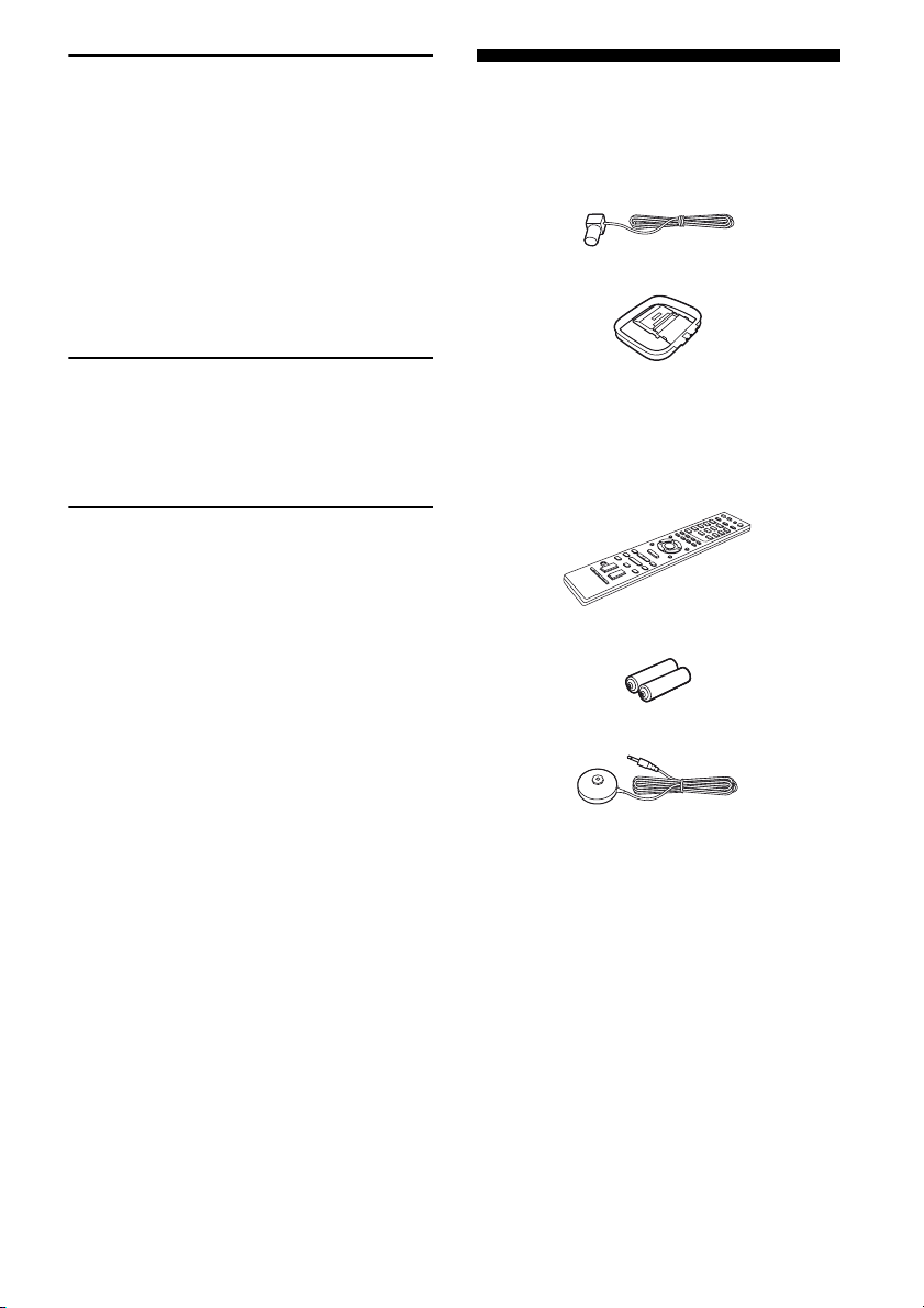
Supplied accessories
• Operating instructions (this manual)
• Quick Setup Guide
• FM wire antenna (aerial) (1)
• AM loop antenna (aerial) (1)
Using the Remote
Programming the remote............................. 85
Clearing all the contents of the remote’s
memory .................................................. 90
Additional Information
Glossary ...................................................... 90
Precautions .................................................. 93
Troubleshooting .......................................... 95
Specifications ............................................ 101
Index.......................................................... 103
• Remote commander (1)
– RM-AAP049 (Models of area code U2
only)
– RM-AAP050 (Models of area code CEL,
CEK only)
• R6 (size-AA) batteries (2)
• Optimizer microphone (ECM-AC2) (1)
GB
7
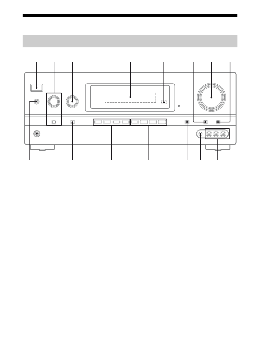
Description and location of parts
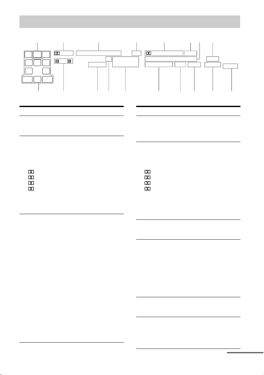
Front panel
?/1
65
7841 32
qg
qh
A ?/1 (on/standby) (page 34, 48, 55)
B TONE +/–, TONE MODE (page 81)
C INPUT SELECTOR (page 43)
D Display (page 9)
E Remote sensor
Receives signals from remote commander.
F DIMMER (page 85)
G MASTER VOLUME (page 42, 43)
H MUTING (page 43)
I VIDEO 2 IN jacks (page 30)
qa q; 9qsqdqf
J AUTO CAL MIC jack (page 36)
K DISPLAY (page 44)
L 2CH/A.DIRECT, A.F.D., MOVIE, MUSIC
(page 51)
M TUNING MODE, TUNING +/–,
MEMORY/ENTER (page 46)
N INPUT MODE (page 69)
O PHONES jack (page 95)
P SPEAKERS (page 34)
GB
8
Indicators on the display
LH
SW
L RC
SL SRS
SBL SBRSB
qk
RH
PLII x z
LFE
HDMI COAXANALOG OPT ARC
D.RANGE ST
456 8213 7
NEO:6
TrueHD
D + EX
MSTR HI RESEQ RDS MEM LBR
DTS-HD
DTS-ES LPCM SLEEP
96/24
S-AIR
BI-AMP
q;
SP A B
9qaqsqdqfqhqj qg
Indicator and explanation
A SW
Lights up when the audio signal is output from
the SUBWOOFER jack.
B Dolby Pro Logic indicators
Lights up one of the respective indicators when
the receiver performs Dolby Pro Logic
processing. This matrix surround decoding
technology can enhance input signals.
PL
PL II
PL IIx
PL IIz
Note
These indicators may not light up depending on
the speaker pattern setting.
C Input indicators
Light up to indicate the current input.
ANALOG
Lights up when INPUT MODE is set to
“ANALOG” or no digital signals are detected
when INPUT MODE is set to “AUTO” (page
69).
HDMI
Lights up when the receiver recognizes a
component connected via an HDMI IN jack
(page 24).
COAX
Lights up when INPUT MODE is set to
“AUTO” and the source signal is a digital signal
being input through the COAXIAL jack (page
69).
OPT
Lights up when INPUT MODE is set to
“AUTO” and the source signal is a digital signal
being input through the OPTICAL jack (page
69).
Dolby Pro Logic
Dolby Pro Logic II
Dolby Pro Logic IIx
Dolby Pro Logic IIz
Indicator and explanation
D ARC
Lights up when TV input is selected and the
Audio Return Channel (ARC) signals are
detected (page 60).
E Dolby Digital Surround indicators
Lights up one of the respective indicators when
the receiver is decoding the corresponding
Dolby Digital format signals.
D
D EX
D+
TrueHD
Note
When playing a Dolby Digital format disc, be
sure that you have made digital connections and
that INPUT MODE is set to “AUTO” (page 69).
F NEO:6
Lights up when DTS Neo:6 Cinema/Music
decoder is activated (page 51).
G DTS-HD indicators
Lights up one of the respective indicators when
the receiver is decoding the corresponding DTSHD format signals.
DTS-HD MSTR
DTS-HD HI RES
DTS-HD LBR
H S-AIR
Lights up when the S-AIR transmitter (not
supplied) is inserted.
I SP A/SP B/SP A B
Lights up according to the speaker system used
(page 34). However, these indicators do not
light up if the speaker output is turned off or if
headphones are connected.
Dolby Digital
Dolby Digital Surround EX
Dolby Digital Plus
Dolby TrueHD
DTS-HD Master Audio
DTS-HD High Resolution
Audio
DTS-HD Low Bit Rate
Audio
continued
GB
9
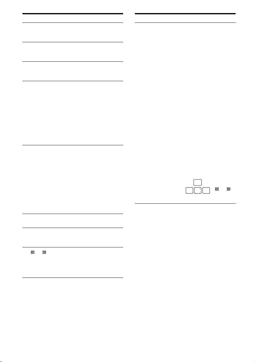
Indicator and explanation
J BI-AMP
Lights up when surround back speakers
selection is set to “BI-AMP” (page 71).
K SLEEP
Lights up when the Sleep Timer is activated
(page 45).
L LPCM
Lights up when the receiver is decoding the
Linear PCM signals.
M DTS(-ES) indicators
Lights up when the receiver is decoding the
DTS or DTS-ES signals.
DTS
DTS-ES
DTS 96/24
Note
When playing a DTS format disc, be sure that
you have made digital connections and that
INPUT MODE is set to “AUTO” (page 69).
N Tuning indicators
Lights up when the receiver tunes in radio
stations.
RDS (Models of area code CEL, CEK
only)
A station that provides RDS services is tuned in.
MEM
Lights up when a memory function, such as
Preset Memory (page 48), etc., is activated.
ST
Stereo broadcast
O EQ
Lights up when the equalizer is activated.
P D.RANGE
Lights up when dynamic range compression is
activated (page 77).
Q
LFE
Lights up when the disc being played back
contains an LFE (Low Frequency Effect)
channel and the LFE channel signal is actually
being reproduced.
DTS
DTS-ES
DTS 96 kHz/24 bit
Indicator and explanation
R Playback channel indicators
The letters (L, C, R, etc.) indicate the channels
being played back. The boxes around the letters
vary to show how the receiver downmixes or
upmixes the source sound (based on the speaker
settings).
LH
RH
L
R
C
SL
SR
S
SBL
SBR
SB
Front Left High
Front Right High
Front Left
Front Right
Center (monaural)
Surround Left
Surround Right
Surround (monaural or the
surround components
obtained by Pro Logic
processing)
Surround Back Left
Surround Back Right
Surround Back (the
surround back components
obtained by 6.1 channel
decoding)
Example:
Speaker pattern: 3/0.1
Recording format: 3/2.1
Sound Field: A.F.D. AUTO
SW
L RC
SL SR
LFE
10
GB
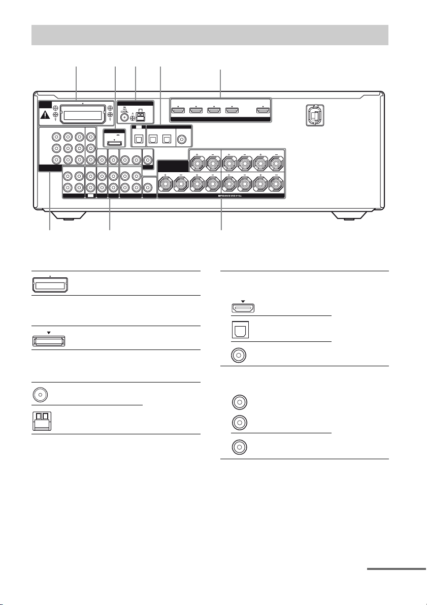
Rear panel
4, 53421
EZW-T100
IN 3 IN 2 IN 1
Y
P
B
/
C
B
PR/
C
R
COMPONENT VIDEO
ASSIGNABLE (INPUT ONLY)
AUDIO
OUT
L
R
SA-CD/CD/CD-R
MONITOR
OUT
AUDIO
AUDIOINAUDIO
IN
SAT/CATV SUBWOOFER
TV
ANTENNA
AM
TV
OPTICAL
VIDEO
IN
AUDIO
IN
IN
VIDEO
OUT
MONITOR
AUDIO
OUT
DIGITAL
SAT
CATV
OPTICAL
DMPORT
DC5V
0.7A MAX
VIDEO
VIDEO
VIDEO
IN
IN
OUT
AUDIO
AUDIO
IN
IN
OUT
BD
VIDEO 1
A S-AIR section (page 32)
EZW-T100 slot
B DMPORT section (page 23)
DMPORT jack
C ANTENNA section (page 32)
FM ANTENNA jack
AM ANTENNA terminals
IN 4 IN 3 IN 2 IN 1 TV OUT
ASSIGNABLE (INPUT ONLY)
(A
S
/
IN
SURROUND BACK/
FRONT HIGH/
BI-AMP/ FRONT B
HDMI
S
IG
N
A
B
LE
)
D
V
D
BD
IN
IN
COAXIAL
CENTER
LR LR
SPEAKERS
645
D Audio signal section
ARC
SURROUND
LR
FRONT A
DIGITAL INPUT/OUTPUT jacks (page 21,
24, 27, 28, 29)
HDMI IN/OUT
OPTICAL IN
COAXIAL IN
ANALOG INPUT/OUTPUT jacks (page 21,
23, 27, 29, 30)
White (L)
Red (R)
AUDIO
IN/OUT
Black
AUDIO OUT
continued
11
GB
E Video signal section*
The image quality depends on the connecting
jack.
DIGITAL INPUT/OUTPUT
jacks (page 21, 24)
HDMI IN/OUT
COMPONENT VIDEO
INPUT/OUTPUT jacks (page
21, 27, 28, 29)
Green
(Y)
Blue
(P
B/CB)
Red
(P
R/CR)
Y, PB/CB, PR/CR
IN/OUT
High
quality
image
COMPOSITE VIDEO INPUT/
OUTPUT jacks (page 21, 27,
29, 30)
Yellow
VIDEO IN/OUT
* You can watch the selected input image when you
connect the HDMI TV OUT or MONITOR OUT
jack to a TV (page 21, 24).
F SPEAKERS section (page 19)
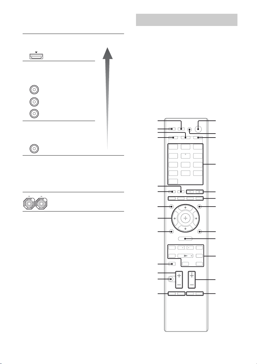
Remote commander
You can use the supplied remote to operate the
receiver and to control the Sony audio/video
components that the remote is assigned to
operate.
You can also program the remote to control
non-Sony audio/video components. For details,
see “Programming the remote” (page 85).
• RM-AAP049 (Models of area
code U2 only)
• RM-AAP050 (Models of area
code CEL, CEK only)
wg
wf
wd
ws
wa
w;
ql
BD DVD
TV
SA-CD/
CD
HDMI 4
SAT/
CATV
VIDEO 1 VIDEO 2
TUNERDMPORT
HDMI 3HDMI 2HDMI 1
1
2
3
4
5
6
7
12
qk
O
qj
MENU
<
.
mM
qh
Xx
<
>
8
9
q;
qg
qf
qd
GB
qa
qs

To control the receiver
Be sure to press AMP (C) to change the
remote button function to control the receiver.
Name and function
A ?/1b) (on/standby)
Turns the receiver on or sets it to standby mode.
Saving the power in standby mode
When “CTRL: HDMI” is set to “CTRL OFF”
(page 76) and “S-AIR STBY” is set to “STBY
OFF” (page 76).
C AMP
The button lights up and activates the receiver
operation (page 38, 44, 45).
D Input buttons
Selects the component you want to play back or
record. When you press any of the input buttons,
the receiver turns on. The buttons are initial
assigned to control Sony components.
Numeric buttons
Presets or tunes to preset stations.
c)
ENTER
Enters the selection during tuner operation.
MEMORY
Stores a station during tuner operation.
E SOUND FIELD +/–
Selects a sound field (page 51).
G AMP MENU
Displays the menu to operate the receiver.
I MENU/HOME
Displays the receiver menus.
J TUNING +/–
Scans a station.
D.TUNING
Enters direct tuning mode.
K PRESET +
Selects preset stations.
L SLEEP
Activates the Sleep Timer function and the
duration which the receiver turns off
automatically.
N MUTING (RM-AAP049 only)
(RM-AAP050 only)
Turns off the sound temporarily. Press again to
restore the sound.
O MASTER VOL +/– (RM-AAP049 only)
+/– (RM-AAP050 only)
Adjust the volume level of all speakers at the
same time.
c)
(number 5a))
c)
a)
/–
Name and function
Q RETURN/EXIT O
Returns to the previous menu.
R
T DISPLAY
U NIGHT MODE
V SHIFT
Y RM SET UP
a)
b)
c)
V/v/B/b
,
Press V/v/B /b to select the settings, then press
to enter the selection.
Views information on the display.
Activates the Night Mode function (page 55).
The button lights up and activates the buttons
with pink printing.
Set up the remote.
The following buttons have tactile dots. Use the
tactile dots as references when operating the
receiver.
– number 5, VIDEO 1
– N
– PRESET +, TV CH + (RM-AAP049 only),
PROG + (RM-AAP050 only), c (RM-AAP050
only)
If you press ?/1 (A) and AV ?/1 (B)
simultaneously, the receiver and connected
components will turn off (SYSTEM STANDBY).
Press SHIFT (V) then only press this button.
continued
13
GB
To control a Sony TV
Press TV (W), then press the yellow printing
button to select the function you want.
Name and function
B AV ?/1b) (on/standby)
Turns on or off the TV.
D Numeric buttons (number 5
Selects the TV channels.
-/--, >10
Selects the channel entry mode.
ENTER
Enters the value.
/ (Text) (RM-AAP050 only)
Displays text information.
F Color buttons
Displays an operation guide on the TV screen
when the color buttons are available. Follow the
operation guide to perform a selected operation.
H TOOLS/OPTIONS
Displays the TV options.
I MENU/HOME
Displays the TV menus.
a)
K TV CH +
PROG +
/– (RM-AAP049 only)
a)
/– (RM-AAP050 only)
Selects the preset TV channels.
a)
/C (RM-AAP050 only)
c
In text mode: Selects the next or previous page.
M TV INPUT (RM-AAP049 only)
(Input select) (RM-AAP050 only)
Selects the input signal (TV or video).
(Text hold) (RM-AAP050 only)
In text mode: Holds the current page.
WIDE (RM-AAP049 only)
(Wide mode) (RM-AAP050 only)
Selects the wide picture mode.
N MUTING (RM-AAP049 only)
(RM-AAP050 only)
Activates the TV’s muting function.
O TV VOL +/– (RM-AAP049 only)
2 +/– (RM-AAP050 only)
Adjusts the TV volume.
Q RETURN/EXIT O
Returns to the previous TV menu.
S GUIDE (RM-AAP049 only)
(Guide) (RM-AAP050 only)
Displays the on-screen program guide.
a)
)
Name and function
T DISPLAY (RM-AAP049 only)
Selects information of TV.
, (Info, Text reveal)
(RM-AAP050 only)
Displays information such as current channel
number and screen mode.
In text mode: Reveals hidden information (e.g.
answers to a quiz).
X THEATER (RM-AAP049 only)
THEATRE (RM-AAP050 only)
Sets the optimal picture settings automatically
for watching movies when you connect a Sony
TV that is compatible with the THEATER or
THEATRE button function (page 59).
a)
The following buttons have tactile dots. Use the
tactile dots as references when operating the
receiver.
– number 5, VIDEO 1
– N
– PRESET +, TV CH + (RM-AAP049 only),
PROG + (RM-AAP050 only), c (RM-AAP050
only)
b)
If you press ?/1 (A) and AV ?/1 (B)
simultaneously, the receiver and connected
components will turn off (SYSTEM STANDBY).
The function of AV ?/1 (B) changes
automatically each time you press the input
buttons (D).
14
GB
To control other Sony components
Name
B AV ?/1
D Numeric
buttons
-/--c), >10
ENTER
F Color
buttons
H TOOLS/
OPTIONS
Blu-ray
disc, DVD
player
b)
Power Power Power Power Power Power Power
Channel Channel Channel Channel Channel Track Track
a)c)
c)
Clear Channel
c)
Enter Enter Enter Enter Enter Enter
Menu,
guide
Options
menu
Satellite
tuner
entry mode,
clear
Menu,
guide
– – Options
VCR PSX DVD/VCR
Channel
entry mode
Clear Clear >10 >10
COMBO,
DVD/HDD
COMBO
–––––
menu
Options
menu
VCD,
LD player
––
I MENU/HOME Menu Menu Menu Menu Menu – –
J ./>
<
m/M
N
X
x
K PRESET
+a)/–
k)
Skip
track
/ R e pl a y /
<
a)k)
k)
k)
Fast
forward
scene
k)
Search
forward,
backward
Play– PlayPlayPlayPlayPlay
Pause – Pause Pause Pause Pause Pause
Stop– StopStopStopStopStop
Preset
channel
–Skip
track
– – – R e p l a y/
–Fast
Preset
channel
forward,
rewind
Preset
channel
Skip
track
Search
forward,
backward
– Preset
Search
index
Fast
forward
scene
Search
forward,
backward
channel
Skip
track
––
Search
forward,
backward
Side A, Bg)–
L F1 HDD mode – – – DVD mode – –
F2 BD,
M BD/DVD
TOP MENU
BD/DVD
DVD mode
On-screen
guide
Menu – – Menu Menu – –
–––VHS mode––
– – On-screen
guide
On-screen
guide
––
MENU
P DISC SKIP Skip disc––––Skip disc
Q RETURN/
EXIT O
Return Return,
exit
– Return Return Return –
R Enter Enter Enter Enter Enter – –
V/v/B/b Select Select Select Select Select – –
S GUIDEi),
j)
(Guide)
EPGEPG–EPG–––
T DISPLAY Display Display Display Display Display Display Display
g)
CD player,
MD/DAT/
Tap e d e ck
Enter
Skip
track
Search
forward,
backward
h)
Skip disc
d)
f)
e)
e)
continued
15
GB
a)
The following buttons have tactile dots. Use the
tactile dots as references when operating the
receiver.
– number 5, VIDEO 1
– N
– PRESET +, TV CH + (RM-AAP049 only),
PROG + (RM-AAP050 only), c (RM-AAP050
only)
b)
If you press ?/1 (A) and AV ?/1 (B)
simultaneously, the receiver and connected
components will turn off (SYSTEM STANDBY).
The function of AV ?/1 (B) changes
automatically each time you press the input
buttons (D).
c)
Press SHIFT (V) then only press this button.
d)
CD player, MD deck and tape deck only.
e)
CD player and MD deck only.
f)
CD player, MD deck and DAT deck only.
g)
LD player only.
h)
VCD player only.
i)
RM-AAP049 only.
j)
RM-AAP050 only.
k)
This button is also available for DIGITAL MEDIA
PORT adapter operation. For details on the
function of the button, refer to the operating
instructions supplied with the DIGITAL MEDIA
PORT adapter.
Notes
• Some functions explained in this section may not
work depending on the model.
• The above explanation is intended to serve as an
example only. Therefore, depending on the
component, the above operation may not be
possible or may operate differently than described.
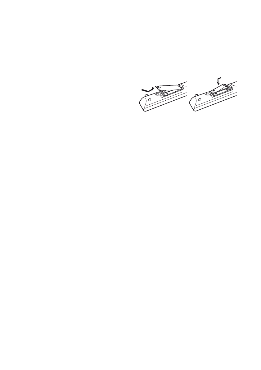
Inserting batteries into the
remote
Insert two R6 (size-AA) batteries in the
RM-AAP049 (Models of area code U2 only)
or RM-AAP050 (Models of area code CEL,
CEK only) Remote Commander.
Observe the correct polarity when installing
batteries.
Notes
• Do not leave the remote in an extremely hot or
humid place.
• Do not use a new battery with old ones.
• Do not mix manganese batteries and other kinds of
batteries.
• Do not expose the remote sensor to direct sunlight
or lighting apparatuses. Doing so may cause a
malfunction.
• If you do not intend to use the remote for an
extended period of time, remove the batteries to
avoid possible damage from battery leakage and
corrosion.
• When you replace the batteries, the programmed
remote codes may be cleared. If this happens,
program the remote codes again (page 85).
• When the remote no longer operates the receiver,
replace all the batteries with new ones.
16
GB
Connections
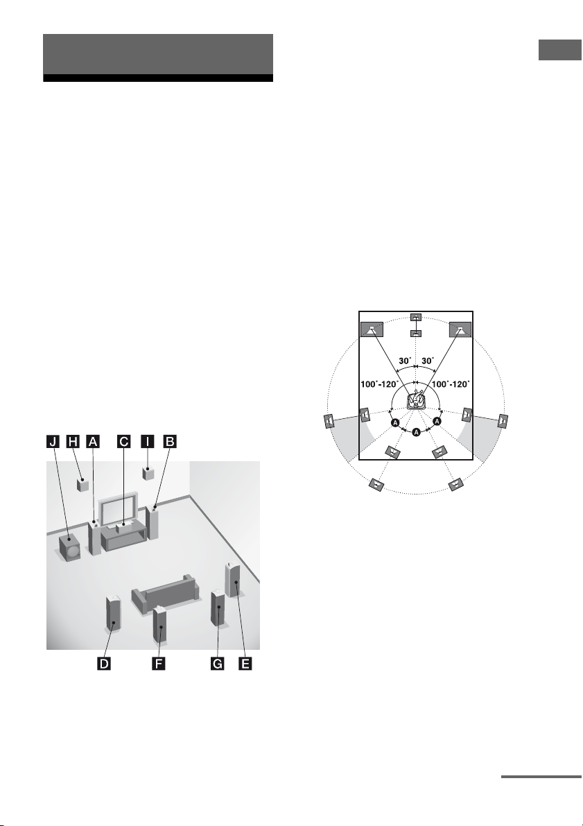
1: Installing the speakers
This receiver allows you to use a 7.1 channel
system (7 speakers and one subwoofer).
To fully enjoy theater-like multi channel
surround sound requires five speakers (two
front speakers, a center speaker, and two
surround speakers) and a subwoofer (5.1
channel).
You can enjoy high fidelity reproduction of
DVD software recorded sound in the Surround
EX format if you connect additional one
surround back speaker (6.1 channel) or two
surround back speakers (7.1 channel).
You can enjoy vertical sound effects if you
connect additional two front high speakers
(7.1 channel) in PLIIz mode (page 52).
Example of speaker system
configuration
AFront speaker (Left)
BFront speaker (Right)
CCenter speaker
DSurround speaker (Left)
ESurround speaker (Right)
FSurround back speaker (Left)*
GSurround back speaker (Right)*
HFront high speaker (Left)*
IFront high speaker (Right)*
JSubwoofer
* You cannot use the surround back speakers and the
front high speakers simultaneously.
Tips
• When you connect a 7.1 channel speaker system
with two surround back speakers, all angle A
should be the same.
Connections
continued
17
GB
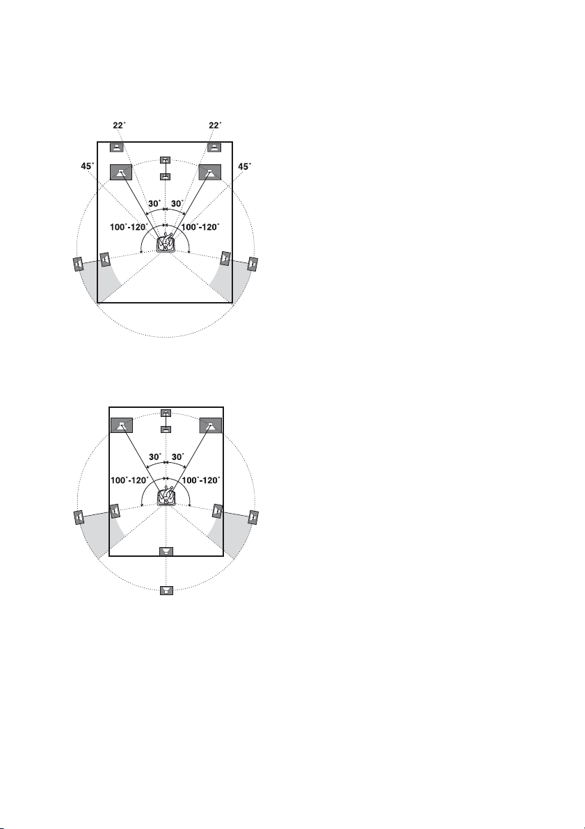
• When you connect a 7.1 channel speaker system
with two front high speakers, place the front high
speakers
– at an angle between 22° to 45°.
– at least 1 meter (3.3 feet) directly above the front
speakers.
• When you connect a 6.1 channel speaker system,
place the surround back speaker behind the
listening position.
• Since the subwoofer does not emit highly
directional signals, you can place it wherever you
want.
GB
18
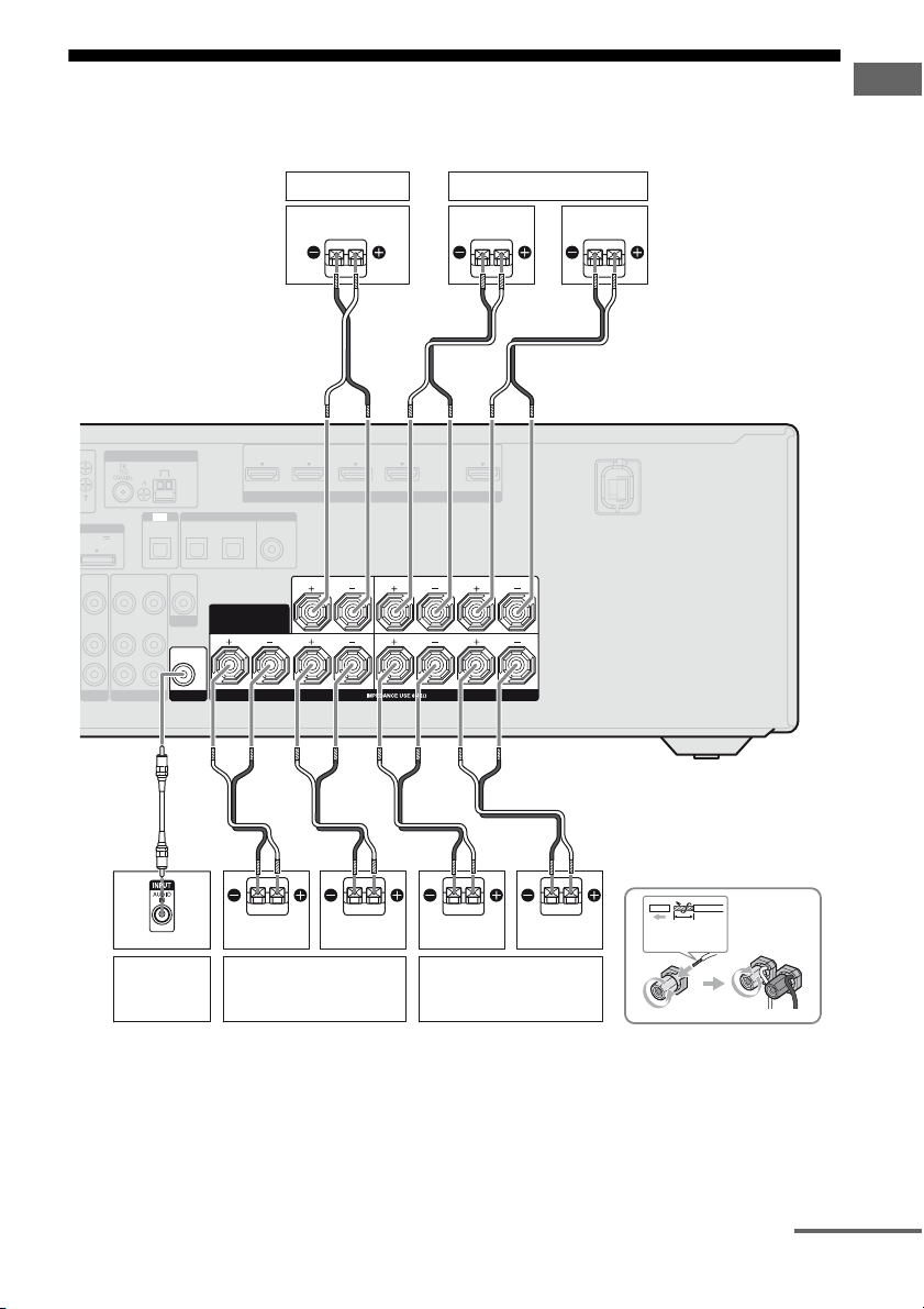
2: Connecting the speakers
Before connecting the cords, be sure to disconnect the AC power cord (mains lead).
Connections
DMPORT
DC5V
0.7A MAX
VIDEO
IN
AUDIO
IN
BD
VIDEO
AUDIO
OUT
OUT
ANTENNA
VIDEO 1
A
TV
OPTICAL
VIDEO
IN
AUDIO
IN
AM
IN
VIDEO
OUT
MONITOR
AUDIO
OUT
SUBWOOFER
Center speaker
B
IN 4 IN 3 IN 2 IN 1 TV OUT
ASSIGNABLE (INPUT ONLY)
COAXIAL
DVD
IN
HDMI
CENTER
LR LR
SPEAKERS
(ASSIGNABLE)
DIGITAL
SAT
/
BD
CATV
IN
IN
OPTICAL
SURROUND BACK/
FRONT HIGH/
BI-AMP/ FRONT B
B
R
B
Surround speaker
Right
ARC
SURROUND
FRONT A
Left
B
L
Left
a)
Subwoofer
Right
b)
Surround back/
Front high/Bi-amplifier/
Front B speaker
A Monaural audio cord (not supplied)
B Speaker cord (not supplied)
LeftRight
Front A speaker
10 mm
(13/32 in)
continued
19
GB
a)
Notes on the SPEAKERS SURROUND BACK/
FRONT HIGH/BI-AMP/FRONT B terminals
connection.
• If you connect only one surround back speaker,
connect it to L of this terminals.
• If you are not using surround back speaker or
front high speakers, and you have an additional
front speaker system, connect the additional
front speaker system to this terminals.
Set “SB ASSIGN” to “SPK B” in the SPEAKER
menu (page 80).
You can select the front speaker system you
want using the SPEAKERS button on the
receiver (page 34).
• If you are not using surround back speaker or
front high speakers, you can connect the front
speakers to this terminals using bi-amplifier
connection (page 20).
b)
When you connect a subwoofer with an auto
standby function, turn off the function when
watching movies. If the auto standby function is
set to on, it turns to standby mode automatically
based on the level of the input signal to a
subwoofer, then sound may not be output.
Notes
• Before connecting the AC power cord (mains
lead), make sure that metalic wires of the speaker
cords are not touching each other between the
SPEAKERS terminals.
• After you have install and connect your speaker, be
sure to select the speaker pattern from SPEAKER
menu (page 78).
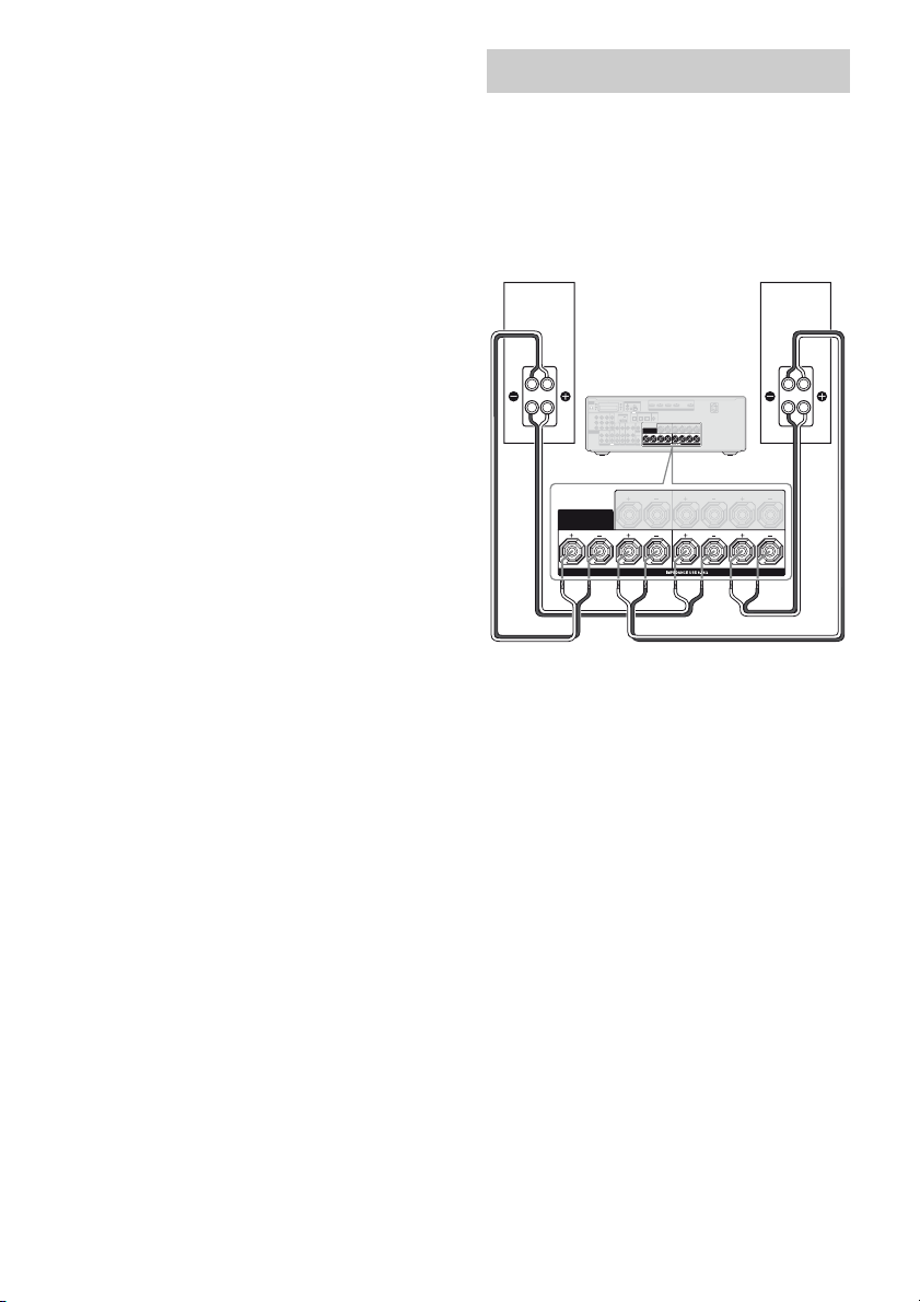
Bi-amplifier connection
If you are not using surround back speakers or
front high speakers, you can connect the front
speakers to the SPEAKERS SURROUND
BACK/FRONT HIGH/BI-AMP/FRONT B
terminals using a bi-amplifier connection.
Front speaker
(Right)
Hi
ANTENNA
EZW-T100
IN 4 IN 3 IN 2 IN 1 TV OUT
AM
ASSIGNABLE (INPUT ONLY)
HDMI
(
A
S
S
I
G
N
A
B
L
E
)
TV
D
I
G
I
T
A
L
MONITOR
IN 3 IN 2 IN 1
OUT
DMPORT
DC5V
SAT
/
Y
0.7A MAX
D
V
D
BD
CATV
IN
I
N
IN
IN
C
O
A
XI
A
L
OPTICAL
Lo
SURROUND BACK/
FRONT HIGH/
BI-AMP/ FRONT B
OPTICAL
P
B
/
C
B
VIDEOINVIDEO
VIDEO
VIDEO
VIDEO
SURROUND
CENTER
OUT
IN
OUT
IN
PR/
C
R
SURROUND BACK/
FRONT HIGH/
MONITOR
COMPONENT VIDEO
AUDIO
AUDIO
AUDIOINAUDIO
AUDIO
AUDIO
AUDIO
ASSIGNABLE (INPUT ONLY)
BI-AMP/ FRONT B
OUT
IN
IN
IN
OUT
IN
AUDIO
OUT
BD
VIDEO 1
CENTER
LR LR
SPEAKERS
FRONT A
LR LR
SPEAKERS
L
R
SAT/CATV SUBWOOFER
TV
SA-CD/CD/CD-R
Connect the jacks on the Lo (or Hi) side of the
front speakers to the SPEAKERS FRONT A
terminals, and connect the jacks on the Hi (or
Lo) side of the front speakers to the
SPEAKERS SURROUND BACK/FRONT
HIGH/BI-AMP/FRONT B terminals.
Make sure that metal fittings of Hi/Lo attached
to the speakers have been removed from the
speakers. Not doing so may cause a
malfunction of the receiver.
After you have made the bi-amplifier
connection, set “SB ASSIGN” to “BI-AMP”
in the SPEAKER menu (page 71).
ARC
LR
Front speaker
SURROUND
LR
FRONT A
(Left)
Hi
Lo
20
GB
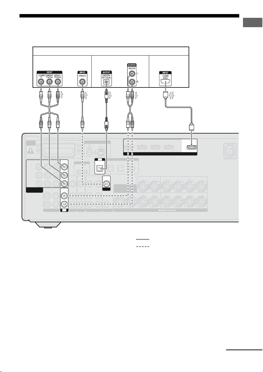
3: Connecting the TV
Before connecting cords, be sure to disconnect the AC power cord (mains lead).
TV
Video signals
Audio signals
Audio/Video
signals
Connections
EZW-T100
IN 3 IN 2 IN 1
Y
P
B
/
C
B
PR/
C
R
COMPONENT VIDEO
ASSIGNABLE (INPUT ONLY)
AUDIO
OUT
L
R
SA-CD/CD/CD-R
MONITOR
OUT
DMPORT
VIDEO
IN
AUDIO
AUDIO
AUDIO
IN
IN
IN
SAT/CATV SUBWOOFER
TV
DC5V
0.7A MAX
VIDEO
IN
AUDIO
IN
BD
BA
VIDEO
OUT
AUDIO
OUT
VIDEO 1
ANTENNA
TV
OPTICAL
VIDEO
IN
AUDIO
IN
AM
IN
VIDEO
OUT
MONITOR
AUDIO
OUT
C
DIGITAL
SAT
/
CATV
IN
OPTICAL
SURROUND BACK/
BI-AMP/ FRONT B
A Component video cord (not supplied)
B Video cord (not supplied)
C Optical digital cord (not supplied)
D Audio cord (not supplied)
E HDMI cable (not supplied)
We recommend that you use a Sony HDMI
cable.
a) b) Ea)
FRONT HIGH/
D
IN 4 IN 3 IN 2 IN 1 TV OUT
ASSIGNABLE (INPUT ONLY)
COAXIAL
DVD
IN
HDMI
CENTER
LR LR
SPEAKERS
SURROUND
FRONT A
(ASSIGNABLE)
BD
IN
Recommended connection
Alternative connection
a)
To enjoy TV multi channel surround sound
broadcasting from the speakers connected to the
receiver, connect either C or E.
Be sure to turn off the TV’s volume or activate the
TV’s muting function.
b)
If your TV is compatible with the Audio Return
Channel (ARC) function, the TV sound will output
from the speakers connected to the receiver via
HDMI TV OUT connection. In this case, set
“ARC” to “ARC ON” in HDMI menu (page 60).
ARC
LR
continued
21
GB

Notes
• Be sure to turn on the receiver when the video and
audio signals of a playback component are being
output to a TV via the receiver. Unless the power is
turned on, neither video nor audio signals will be
transmitted.
• Connect image display components such as a TV
monitor or a projector to the HDMI TV OUT or
MONITOR OUT jack on the receiver. You may
not be able to record, even if you connect recording
components.
• Depending on the status of the connection between
the TV and the antenna (aerial), the image on the
TV screen may be distorted. In this case, place the
antenna (aerial) farther away from the receiver.
• When connecting optical digital cords, insert the
plugs straight in until they click into place.
• Do not bend or tie optical digital cords.
Tips
• All the digital audio jacks are compatible with
32 kHz, 44.1 kHz, 48 kHz, and 96 kHz sampling
frequencies.
• The receiver has a video conversion function. For
details, see “Function for conversion of video
signals” (page 31).
22
GB
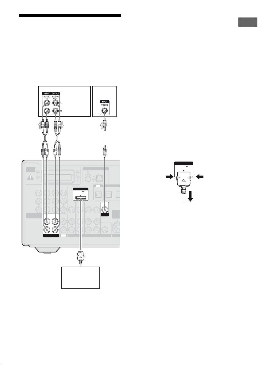
4a: Connecting the audio
O
O
M
components
The following illustration shows how to
connect a Super Audio CD player, CD player,
CD recorder and DIGITAL MEDIA PORT
adapter. Before connecting cords, be sure to
disconnect the AC power cord (mains lead).
EZW-T100
IN 3 IN 2 IN 1
Y
P
B
/
C
B
PR/
C
R
COMPONENT VIDEO
ASSIGNABLE (INPUT ONLY)
AUDIO
OUT
L
R
SA-CD/CD/CD-R
Super Audio
CD player,
CD player,
CD recorder
A
MONITOR
OUT
DMPORT
VIDEO
IN
AUDIOINAUDIO
AUDIO
IN
IN
SAT/CATV SUBWOOFER
TV
DC5V
0.7A MAX
VIDEO
IN
AUDIO
IN
BD
AUDIO
VIDEO
OUT
OUT
ANTENNA
VIDEO 1
OPTICAL
VIDEO
IN
AUDIO
IN
TV*
B
AM
TV
DIGITAL
SAT
/
CATV
IN
IN
OPTICAL
VIDEO
OUT
SURR
MONITOR
BI-A
AUDIO
OUT
Notes on connecting DIGITAL
MEDIA PORT adapter
• When connecting the DIGITAL MEDIA
PORT adapter, be sure the connector is
inserted with the arrow mark facing towards
the arrow mark on the DMPORT jack.
• Be sure to make DMPORT connections
firmly, insert the connector straight in.
• As the connector of the DIGITAL MEDIA
PORT adapter is fragile, be sure to handle
with care when placing or moving the
receiver.
• Do not connect an adapter other than the
DIGITAL MEDIA PORT adapter.
• Do not connect or disconnect the DIGITAL
MEDIA PORT adapter while the receiver is
turned on.
To detach the DIGITAL MEDIA
PORT adapter from DMPORT
jack
DMPORT
DC5V
0.7A MAX
2
Press and hold both sides of the connector and
FR
then pull out the connector.
Connections
1
DIGITAL MEDIA
PORT adapter
A Audio cord (not supplied)
B Video cord (not supplied)
* You can enjoy the images from the components
connected to the DIGITAL MEDIA PORT adapter
when you connect the TV to the receiver.
23
GB

4b: Connecting the video components
Tip
Components to be connected
Connect your video components according to
the table below.
Component Page
Blu-ray disc player* 24, 27
DVD player* 24, 28
DVD recorder* 24, 28, 30
Satellite tuner*, Cable TV tuner* 24, 29
“PlayStation 3”* 24
VCR 30
Camcorder, video game, etc. 30
* We recommend that you connect your video
components via HDMI connection if they have
HDMI jacks.
You can watch the selected input image when
you connect the HDMI TV OUT or
MONITOR OUT jack to a TV (page 21).
The receiver equipped with video signals
converting function. For details, see “Function
for conversion of video signals” (page 31).
If you want to connect several
digital components, but cannot
find an unused input
See “Enjoying the sound/images from other
inputs” (page 69).
Notes
• Before connecting cords, be sure to disconnect the
AC power cord (mains lead).
• I t i s n ot nece ss ar y t o connect all the cords. Connect
according to the availability of jacks on the
connected components.
• Be sure to turn on the receiver when the video and
audio signals of a playback component are being
output to a TV via the receiver. Unless the power is
turned on, neither video nor audio signals will be
transmitted.
• When connecting optical digital cords, insert the
plugs straight in until they click into place.
• Do not bend or tie optical digital cords.
All the digital audio jacks are compatible with
32 kHz, 44.1 kHz, 48 kHz, and 96 kHz sampling
frequencies.
Connecting components with
HDMI jacks
HDMI is the abbreviated name for HighDefinition Multimedia Interface. It is an
interface which transmits video and audio
signals in digital format.
HDMI features
• A digital audio signals transmitted by HDMI
can be output from the speakers connected to
the receiver. This signal supports Dolby
Digital, DTS, and Linear PCM.
• This receiver can receive multi channel
Linear PCM (up to 8 channels) with a
sampling frequency of 192 kHz or less with
an HDMI connection.
• This receiver supports High Bitrate Audio
(DTS-HD Master Audio, Dolby TrueHD)
and HDMI (Deep Colour (Deep Color),
x.v. Colour (x.v. Color)).
• This receiver supports the Control for HDMI
function. For details, see ““BRAVIA” Sync
Features” (page 56).
• Analog video signals input to the VIDEO
jack, or COMPONENT VIDEO jacks can be
output as HDMI signals (page 31). Audio
signals are not output from HDMI TV OUT
jack when the image is converted.
24
GB

“PlayStation 3”
Audio/video
signals
Satellite tuner,
Cable TV tuner
Audio/video
signals
DVD player, DVD recorder Blu-ray disc player
Audio/video
signals
Audio/video
signals
Connections
AA
DMPORT
DC5V
0.7A MAX
VIDEO
IN
AUDIO
IN
BD
VIDEO
OUT
AUDIO
OUT
VIDEO 1
ANTENNA
OPTICAL
VIDEO
IN
AUDIO
IN
AM
TV
IN
VIDEO
OUT
MONITOR
AUDIO
OUT
EZW-T100
IN 3 IN 2 IN 1
Y
P
B
/
C
B
PR/
C
R
COMPONENT VIDEO
ASSIGNABLE (INPUT ONLY)
AUDIO
OUT
L
R
SA-CD/CD/CD-R
MONITOR
OUT
VIDEO
IN
AUDIO
AUDIOINAUDIO
IN
IN
SAT/CATV SUBWOOFER
TV
A HDMI cable (not supplied)
We recommend that you use a Sony HDMI cable.
IN 4 IN 3 IN 2 IN 1 TV OUT
ASSIGNABLE (INPUT ONLY)
COAXIAL
DVD
IN
HDMI
CENTER
LR LR
SPEAKERS
Audio/video
signals
(ASSIGNABLE)
DIGITAL
SAT
/
BD
CATV
IN
IN
OPTICAL
SURROUND BACK/
FRONT HIGH/
BI-AMP/ FRONT B
SURROUND
TV, etc.*
A
FRONT A
A
ARC
LR
A
* See page 21 for the audio connection of TV to the
receiver.
Notes
• Be sure to change the initial setting of the HDMI
1–4 input button on the remote so that you can use
the button to control your components. For details,
see “Programming the remote” (page 85).
• You can also rename the HDMI input so that it can
be displayed on the receiver’s display. For details,
see “Naming inputs” (page 44).
continued
25
GB

Notes on connecting cables
• Use a High Speed HDMI cable. If you use a
Standard HDMI cable, 1080p or Deep
Colour (Deep Color) images may not be
displayed properly.
• Sony recommends that you use an HDMI
authorized cable or Sony HDMI cable.
• We do not recommend using an HDMI-DVI
conversion cable. When you connect an
HDMI-DVI conversion cable to a DVI-D
component, the sound and/or the image may
not be output. Connect other audio cords or
digital connecting cords, then set
“A. ASSIGN” in AUDIO menu (page 69)
when the sound is not output correctly.
Notes on HDMI connections
• An audio signal input to the HDMI IN jack
is output from the SPEAKERS jacks, HDMI
TV OUT jack and PHONES jack. It is not
output from any other audio jacks.
• Video signals input to the HDMI IN jack can
only be output from the HDMI TV OUT
jack. The video input signals cannot be
output from the VIDEO OUT jacks or
MONITOR OUT jacks.
• When you want to listen to the sound from
the TV speaker, set “AUDIO OUT” to
“TV+AMP” in the HDMI menu (page 84). If
you cannot play back multi channel
software, set to “AMP”. However, the sound
will not output from the TV speaker.
• DSD signals of Super Audio CD are not
input and output.
• The multi/stereo area audio signals of a
Super Audio CD are not output.
• Audio signals (sampling frequency, bit
length, etc.) transmitted from an HDMI jack
may be suppressed by the connected
component. Check the setup of the
connected component if the image is poor or
the sound does not come out of a component
connected via the HDMI cable.
• Sound may be interrupted when the
sampling frequency, the number of channels
or audio output signals from the playback
component is switched.
• When the connected component is not
compatible with copyright protection
technology (HDCP), the image and/or the
sound from the HDMI TV OUT jack may be
distorted or may not be output.
In this case, check the specification of the
connected component.
• Be sure to turn on the receiver when video
and audio signals of a playback component
are being output to a TV through this
receiver. If you set “PASS THRU” to
“OFF”, video and audio signals will not be
transmitted when the power is turned off.
• Set the image resolution of the player to
more than 720p/1080i to enjoy High Bitrate
Audio (DTS-HD Master Audio, Dolby
TrueHD).
• The image resolution of player may need
certain settings be made before you can
enjoy multi channel Linear PCM. Refer to
the operating instructions of the player.
• Not every HDMI component supports all
functions that are defined by the specified
HDMI version. For example, components
that support HDMI, version 1.4, may not
support Audio Return Channel (ARC).
• Refer to the operating instructions of each
connected component for details.
26
GB
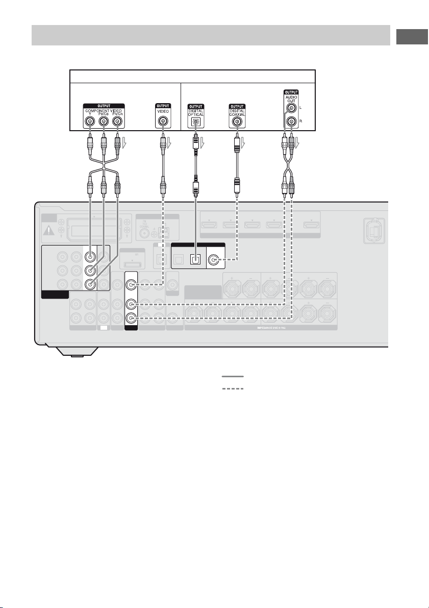
Connecting a Blu-ray disc player
The following illustration shows how to connect a Blu-ray disc player.
Blu-ray disc player
Video signals Audio signals
Connections
AB
DMPORT
DC5V
0.7A MAX
VIDEO
IN
AUDIO
IN
BD
VIDEO
OUT
AUDIO
OUT
VIDEO 1
ANTENNA
OPTICAL
VIDEO
AUDIO
AM
TV
DIGITAL
SAT
/
CATV
IN
IN
OPTICAL
VIDEO
OUT
IN
SURROUND BACK/
FRONT HIGH/
MONITOR
AUDIO
OUT
BI-AMP/ FRONT B
IN
EZW-T100
IN 3 IN 2
Y
B
/
C
B
P
PR/
C
R
COMPONENT VIDEO
ASSIGNABLE (INPUT ONLY)
AUDIO
OUT
L
R
SA-CD/CD/CD-R
MONITOR
IN 1
OUT
VIDEO
IN
AUDIO
AUDIOINAUDIO
IN
IN
SAT/CATV SUBWOOFER
TV
A Component video cord (not supplied)
B Video cord (not supplied)
C Optical digital cord (not supplied)
D Coaxial digital cord (not supplied)
E Audio cord (not supplied)
Notes
• The initial setting of the COMPONENT VIDEO
IN 1 jacks are Blu-ray disc player. If you want to
connect your Blu-ray disc player to the
COMPONENT VIDEO IN 2 or IN 3 jacks, set
“V. ASSIGN” in the VIDEO menu (page 69).
• To input multi channel digital audio from the Bluray disc player, set the digital audio output setting
on the Blu-ray disc player. Refer to the operating
instructions supplied with the Blu-ray disc player.
C
IN 4 IN 3 IN 2 IN 1 TV OUT
(ASSIGNABLE)
BD
IN
COAXIAL
D* E
HDMI
DVD
IN
CENTER
LR LR
SPEAKERS
ASSIGNABLE (INPUT ONLY)
SURROUND
FRONT A
ARC
LR
Recommended connection
Alternative connection
* When you connect a component equipped with a
COAXIAL jack, set “A. ASSIGN” in the AUDIO
menu (page 69).
27
GB
Connecting a DVD player, DVD recorder
The following illustration shows how to connect a DVD player or DVD recorder.
DVD pla ye r, DVD r eco r de r
Video signals Audio signals
AC
DMPORT
DC5V
0.7A MAX
VIDEO
IN
AUDIO
IN
BD
VIDEO
AUDIO
OUT
OUT
ANTENNA
VIDEO 1
OPTICAL
VIDEO
IN
AUDIO
IN
AM
TV
DIGITAL
SAT
/
CATV
IN
IN
OPTICAL
VIDEO
OUT
SURROUND BACK/
MONITOR
BI-AMP/ FRONT B
AUDIO
OUT
EZW-T100
IN 3 IN 1
Y
P
B
/
C
B
PR/
C
R
COMPONENT VIDEO
ASSIGNABLE (INPUT ONLY)
IN 2
AUDIO
OUT
L
R
SA-CD/CD/CD-R
MONITOR
OUT
VIDEO
IN
AUDIO
AUDIOINAUDIO
IN
IN
SAT/CATV SUBWOOFER
TV
A Component video cord (not supplied)
B Optical digital cord (not supplied)
C Coaxial digital cord (not supplied)
Notes
• The initial setting for the DVD input button is as
follows:
– RM-AAP049: DVD player
– RM-AAP050: DVD recorder
To control other components, be sure to change the
initial setting of the DVD input button on the
remote. For details, see “Programming the remote”
(page 85).
• You can also rename the DVD input so that it can
be displayed on the receiver’s display. For details,
see “Naming inputs” (page 44).
B*
IN 4 IN 3 IN 2 IN 1 TV OUT
SURROUND
FRONT A
ARC
LR
(ASSIGNABLE)
BD
IN
FRONT HIGH/
COAXIAL
DVD
IN
ASSIGNABLE (INPUT ONLY)
HDMI
CENTER
LR LR
SPEAKERS
Recommended connection
Alternative connection
* When you connect a component equipped with an
OPTICAL jack, set “A. ASSIGN” in the AUDIO
menu (page 69).
• The initial setting of the COMPONENT VIDEO
IN 2 jacks are DVD player or DVD recorder. If you
want to connect your DVD player or DVD recorder
to the COMPONENT VIDEO IN 1 or IN 3 jacks,
set “V. ASSIGN” in the VIDEO menu (page 69).
• To input multi channel digital audio from the DVD
player or DVD recorder, set the digital audio
output setting on the DVD player or DVD recorder.
Refer to the operating instructions supplied with
the DVD player or DVD recorder.
28
GB
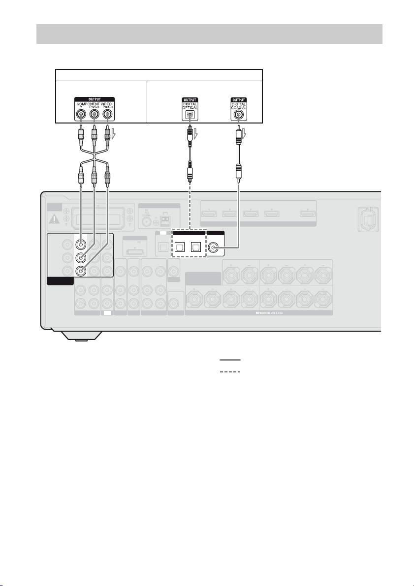
Connecting a satellite tuner, cable TV tuner
The following illustration shows how to connect a satellite tuner or cable TV tuner.
Satellite tuner, Cable TV tuner
Audio signalsVideo signals
Connections
EZW-T100
IN 3
Y
P
B
/
C
B
PR/
C
R
COMPONENT VIDEO
ASSIGNABLE (INPUT ONLY)
IN 2 IN 1
AUDIO
OUT
L
R
SA-CD/CD/CD-R
AUDIO
BA
ANTENNA
MONITOR
OUT
DMPORT
DC5V
0.7A MAX
VIDEO
VIDEO
IN
AUDIO
AUDIO
AUDIO
IN
IN
IN
BD
SAT/CATV
TV
TV
OPTICAL
VIDEO
VIDEO
IN
OUT
IN
AUDIO
AUDIO
IN
OUT
IN
VIDEO 1
AM
IN
MONITOR
SUBWOOFER
AUDIO
VIDEO
OUT
OUT
C
DIGITAL
SAT
/
CATV
IN
OPTICAL
SURROUND BACK/
BI-AMP/ FRONT B
A Component video cord (not supplied)
B Video cord (not supplied)
C Optical digital cord (not supplied)
D Audio cord (not supplied)
Note
The initial setting of the COMPONENT VIDEO IN
3 jacks are satellite tuner or cable TV tuner. If you
want to connect your satellite tuner or cable TV
tuner to the COMPONENT VIDEO IN 1 or IN 2
jacks, set “V. ASSIGN” in the VIDEO menu (page
69).
D
IN 4 IN 3 IN 2 IN 1 TV OUT
ASSIGNABLE (INPUT ONLY)
COAXIAL
DVD
IN
HDMI
CENTER
LR LR
SPEAKERS
(ASSIGNABLE)
BD
IN
FRONT HIGH/
Recommended connection
Alternative connection
SURROUND
FRONT A
ARC
LR
29
GB
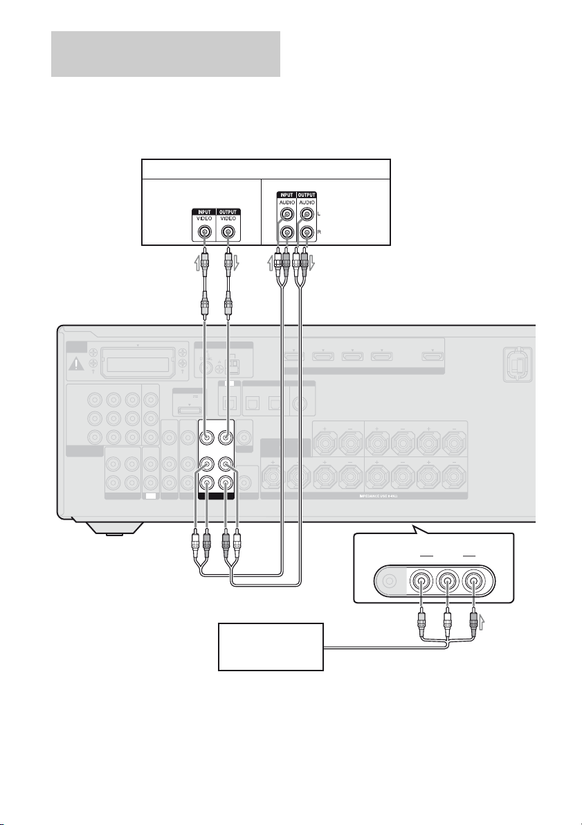
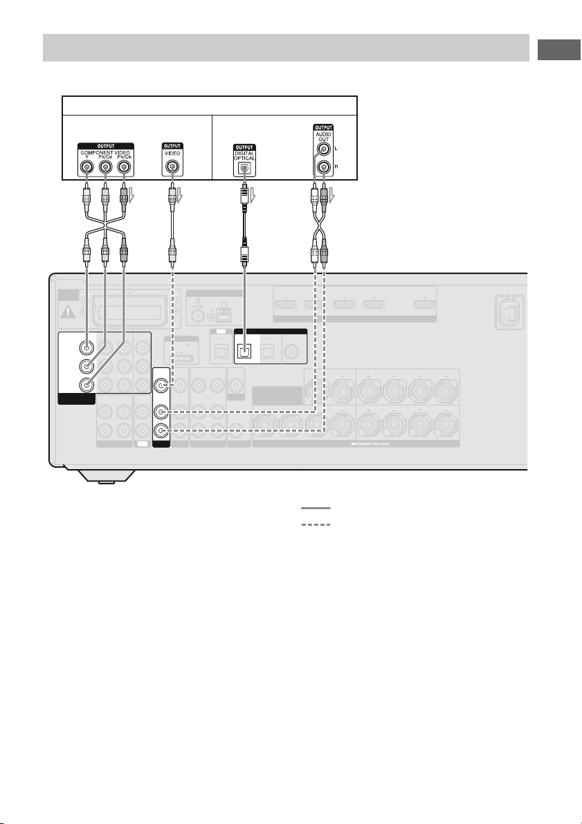
Connecting components with
analog video and audio jack
The following illustration shows how to
connect a component which has analog jacks
such as a VCR, DVD recorder, etc.
VCR, DVD recorder
Video signals
Notes
• Be sure to change the initial setting of the VIDEO
1 input button on the remote so that you can use the
button to control your DVD recorder. For details,
see “Programming the remote” (page 85).
• You can also rename the VIDEO 1 input so that it
can be displayed on the receiver’s display. For
details, see “Naming inputs” (page 44).
Audio signals
EZW-T100
IN 3 IN 2 IN 1
Y
B
/
C
B
P
PR/
C
R
COMPONENT VIDEO
ASSIGNABLE (INPUT ONLY)
AUDIO
OUT
L
R
SA-CD/CD/CD-R
A
MONITOR
OUT
DMPORT
VIDEO
IN
AUDIO
AUDIOINAUDIO
IN
IN
SAT/CATV SUBWOOFER
TV
DC5V
0.7A MAX
VIDEO
IN
AUDIO
IN
BD
VIDEO
AUDIO
OUT
OUT
ANTENNA
VIDEO 1
OPTICAL
VIDEO
IN
AUDIO
IN
AM
TV
DIGITAL
SAT
CATV
IN
IN
OPTICAL
VIDEO
OUT
SURROUND BACK/
MONITOR
AUDIO
OUT
Camcorder,
video game
B
IN 4 IN 3 IN 2 IN 1 TV OUT
ASSIGNABLE (INPUT ONLY)
COAXIAL
DVD
IN
HDMI
CENTER
LR LR
SPEAKERS
AUTO CAL MIC
(ASSIGNABLE)
/
BD
IN
FRONT HIGH/
BI-AMP/ FRONT B
C
ARC
SURROUND
LR
FRONT A
(On the front panel)
VIDEO 2 IN
VIDEO L AUDIO R
A Video cord (not supplied)
B Audio cord (not supplied)
C Audio/video cord (not supplied)
GB
30
 Loading...