


3-856-169-11(1)
FM Stereo
FM-AM Receiver
Operating instructions |
|
EN |
|
|
Mode d’emploi |
|
F |
|
|
STR-DE705
STR-DE605
STR-D650Z
STR-D550Z
© 1996 by Sony Corporation

WARNING
To prevent fire or shock hazard, do not expose the unit to rain or moisture.
This symbol is intended to alert the user to the presence of uninsulated “dangerous voltage” within the product’s
enclosure that may be of sufficient magnitude to constitute a risk of electric shock to persons.
This symbol is intended to alert the user to the presence of important operating and maintenance (servicing) instructions in the literature accompanying the appliance.
IMPORTANT
This equipment has been tested and found to comply with the limits for a Class B digital device, pursuant to Part 15 of the FCC Rules.
These limits are designed to provide reasonable protection against harmful interference in a residential installation. This equipment generates, uses, and can radiate radio frequency energy and, if not installed and used in accordance with the instructions, may cause harmful interference to radio communications. However, there is no guarantee that interference will not occur in a particular installation. If this equipment does cause harmful interference to radio or television reception, which can be determined by turning the equipment off and on, the user is encouraged to try to correct the interference by one or more of the following measures:
-Reorient or relocate the receiving antenna.
-Increase the separation between the equipment and receiver.
-Connect the equipment into an outlet on a circuit different from that to which the receiver is connected.
-Consult the dealer or an experienced radio/TV technician for help.
CAUTION
You are cautioned that any change or modifications not expressly approved in this manual could void your authority to operate this equipment.
Note to CATV system installer
This reminder is provided to call the CATV system installer’s attention to Article 820-40 of the NEC that provides guidelines for proper grounding and, in particular, specifies that the cable ground shall be connected to the grounding system of the building, as close to the point of cable entry as practical.
Owner’s record
The model and serial numbers are located on the rear of the unit. Record the serial number in the space provided below. Refer to them whenever you call upon your Sony dealer regarding this product.
Model No. STR-DE705/STR-DE605/
STR-D650Z/STR-D550Z
Serial No.
For the customers in Canada
CAUTION
TO PREVENT ELECTRIC SHOCK, DO NOT USE THIS POLARIZED AC PLUG WITH AN EXTENSION CORD, RECEPTACLE OR OTHER OUTLET UNLESS THE BLADES CAN BE FULLY INSERTED TO PREVENT BLADE EXPOSURE.
Precautions
On safety
•Should any solid object or liquid fall into the cabinet, unplug the receiver and have it checked by qualified personnel before operating it any further.
On power sources
•Before operating the receiver, check that the operating voltage is identical with your local power supply. The operating voltage is indicated on the nameplate at the rear of the receiver.
•The receiver is not disconnected from the AC power source as long as it is connected to the wall outlet, even if the receiver itself has been turned off.
•If you are not going to use the receiver for a long time, be sure to disconnect the receiver from the wall outlet. To disconnect the AC power cord, grasp the plug itself; never pull the cord.
•One blade of the plug is wider than the other for the purpose of safety and will fit into the wall outlet only one way. If you are unable to insert the plug fully into the outlet, contact your dealer.
•Should the AC power cord need to be changed, have it done at a qualified service shop only.
On placement
•Place the receiver in a location with adequate ventilation to prevent heat buildup and prolong the life of the receiver.
•Do not place the receiver near heat sources, or in a place subject to direct sunlight, excessive dust or mechanical shock.
•Do not place anything on top of the cabinet that might block the ventilation holes and cause malfunctions.
On operation
•Before connecting other components, be sure to turn off and unplug the receiver.
On cleaning
•Clean the cabinet, panel and controls with a soft cloth slightly moistened with a mild detergent solution. Do not use any type of abrasive pad, scouring powder or solvent such as alcohol or benzine.
For the customers in the USA
For detailed safety precautions, see the “IMPORTANT SAFEGUARDS” leaflet.
If you have any question or problem concerning your receiver, please consult your nearest Sony dealer.
2EN
About This Manual
The instructions in this manual are for models STR-DE705, STR-DE605, STRD650Z, and STR-D550Z. Check your model number by looking at the upper right corner of the front panel. In this manual, the STR-DE705 is the model used for illustration purposes. Any difference in operation is clearly indicated in the text, for example, “STR-DE705 only”.
Type of differences
Model |
DE705 |
D650Z |
Feature |
DE605 |
D550Z |
|
|
|
MIX AUDIO Output |
r |
|
|
|
|
Control A1/Control S |
DE705* |
|
|
|
|
Impedance selector |
DE705 |
D650Z |
|
|
|
Programmable remote |
DE705 |
D650Z |
|
DE605** |
|
|
|
|
12 mode surround |
r |
D650Z |
|
|
|
6 mode surround |
|
D550Z |
|
|
|
*USA and Canadian models only
**Canadian model only
Conventions
•The instructions in this manual describe the controls on the receiver. You can also use the controls on the remote if they have the same or similar names as those on the receiver.
•A “Quick Reference Guide” is supplied on page 29.
•The “Remote Button Descriptions” section on page 27 provides an overview of the remote buttons.
•The following icons are used in this manual:
 Indicates that you can use only
  the remote to do the task.
 Indicates hints and tips for
  making the task easier.
This receiver incorporates the Dolby Pro Logic Surround system. Manufactured under license from Dolby Laboratories Licensing Corporation. “Dolby ,” the double-D symbol aand “Pro Logic” are trademarks of Dolby Laboratories Licensing Corporation.
TABLE OF CONTENTS
Getting Started
Unpacking 4
Hookup Overview 4
Antenna Hookups 5
Audio Component Hookups 5
Speaker System Hookups 6
TV/VCR Hookups 7
AC Hookups 8
Before You Use Your Receiver 8
Receiver Operations
Selecting a Component 9
Receiving Broadcasts 10
Presetting Radio Stations 11
Indexing 12
Recording 13
Using the Sleep Timer 14
EN
Using Sound Fields
Using Pre-programmed Sound Fields 15
Taking Advantage of the Sound Fields 16
Customizing Sound Fields 17
Getting the Most Out of Dolby Pro Logic Surround Sound 18
Advanced Remote Operations
Operating One Component While Using Another (background operation) 20
Changing the Factory Setting of a FUNCTION Button 20 Programming the Remote (for STR-DE705/STR-D650Z and Canadian
STR-DE605 only) 21
Additional Information
Troubleshooting 22
Specifications 23
Glossary 24
Rear Panel Descriptions 26
Remote Button Descriptions 27
Index 28
Quick Reference Guide 29
3EN
Getting Started
Unpacking
Check that you received the following items with the receiver:
•FM wire antenna (1)
•AM loop antenna (1)
•Remote commander (remote) (1)
•Size AA (R6) batteries (2)
•Audio/Video cable (1)
(USA and Canadian STR-DE705 only)
•Control S cord (1)
(USA and Canadian STR-DE705 only)
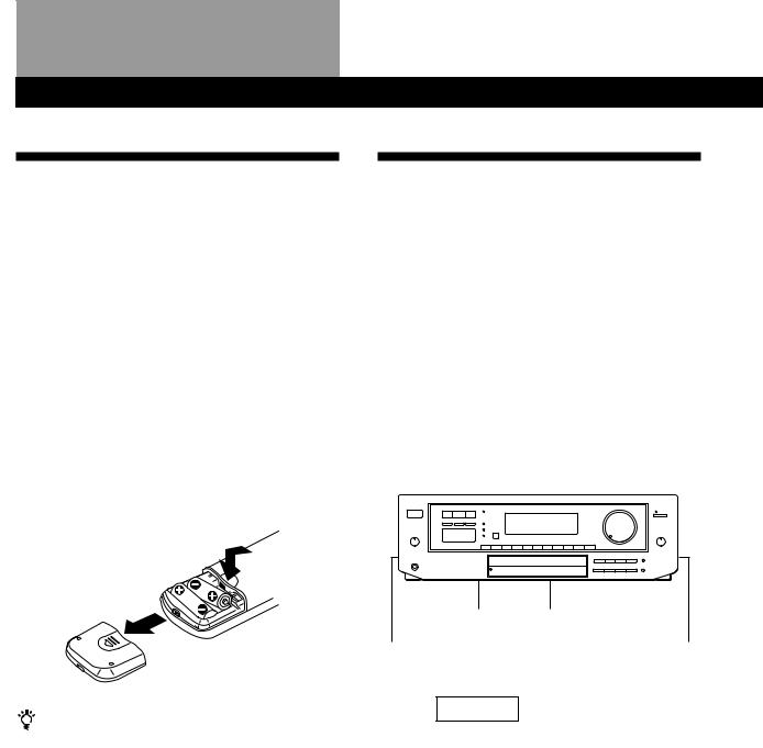
Inserting batteries into the remote
Insert two size AA (R6) batteries with the + and – on the battery compartment. When using the remote, point it at the remote sensor gon the receiver.
When to replace batteries
Under normal use, the batteries should last for about 6 months. When the remote no longer operates the receiver, replace both batteries with new ones.
Notes
•Do not leave the remote in an extremely hot or humid place.
•Do not use a new battery with an old one.
•Do not expose the remote sensor to direct sunlight or lighting apparatuses. Doing so may cause a malfunction.
•If you don’t use the remote for an extended period of time, remove the batteries to avoid possible damage from battery leakage and corrosion.
Hookup Overview
The receiver allows you to connect and control the following audio/video components. Follow the hookup procedures for the components that you want to connect to the receiver on the pages specified. To learn the locations and names of each jacks, see “Rear Panel Descriptions” on page 26.
|
|
|
|
|
|
|
|
|
|
|
|
|
|
|
|
|
|
Antenna Hookups (5) |
||||||||||
|
|
|
|
|
|
|
|
|
|
|
|
|
|
|
|
|
|
|
|
|
|
|
|
|
|
|||
Speaker |
|
TV/VCR Hookups (7, 8) |
AM/FM antenna |
|||||||||||||||||||||||||
|
|
|
|
|
|
|
|
|
|
|
|
|||||||||||||||||
System |
|
|
|
|
|
|
|
|
|
|
|
|
|
|
|
|
|
|
|
|
|
|
|
|||||
|
|
|
|
|
|
|
|
|
|
|
|
|
|
|
|
|
|
|
|
|
|
|
||||||
Hookups (6, 7) |
TV |
|
|
|
|
|
|
|
|
|
|
|
|
|
||||||||||||||
|
|
|
|
|
|
|
|
|
|
|
|
|
|
|
|
|
|
|
|
|
|
|
|
|||||
Front |
|
|
|
|
|
|
|
|
|
|
|
|
|
|
|
|
Front |
|||||||||||
|
|
|
|
|
|
|
|
|
|
|
|
|
|
|
|
|||||||||||||
|
|
|
|
|
VCR |
|
|
|
|
|
|
|||||||||||||||||
speaker |
|
|
|
|
|
|
|
|
|
|
|
speaker |
||||||||||||||||
|
Active |
|
||||||||||||||||||||||||||
|
(L) |
|
|
|
|
|
|
|
|
|
|
|
|
|
|
|
|
(R) |
||||||||||
|
|
|
|
|
|
|
|
|
|
|
LD player |
|
|
|
woofer |
|
|
|
|
|
|
|
|
|||||
|
|
|
|
|
|
|
|
|
|
|
|
|
|
|
|
|
|
|
|
|
|
|
|
|
|
|
|
|
|
|
|
|
|
|
|
|
|
|
|
|
|
|
|
|
|
|
|
|
|
|
|
|
|
|
|
|
|
|
|
|
|
|
|
|
|
|
|
|
|
|
|
|
|
|
|
|
|
|
|
|
|
|
|
|
|
|
|
|
|
|
|
|
|
|
|
|
|
|
|
|
|
|
|
|
|
|
|
|
|
|
|
|
|
|
|
|
|
|
|
|
|
|
|
|
|
|
|
|
|
|
|
|
|
|
|
|
|
|
|
|
|
|
|
|
|
|
|
|
|
|
|
|
|
|
|
|
|
|
|
|
|
|
|
|
|
|
|
|
|
|
|
|
|
|
|
|
|
|
|
|
|
|
|
|
|
|
|
|
|
|
|
|
|
|
|
|
|
|
|
|
|
|
|
|
|
|
|
|
|
|
|
|
|
|
|
|
|
|
|
|
|
|
|
|
|
|
|
|
|
|
|
|
|
|
|
|
|
|
|
|
|
|
|
|
|
|
|
|
|
|
|
|
|
|
|
|
|
|
|
|
|
|
|
|
|
|
|
|
|
|
|
|
|
|
|
|
|
|
|
|
|
|
|
|
|
|
|
|
|
|
|
|
|
|
|
|
|
|
|
|
|
|
|
|
|
|
|
|
|
|
|
|
|
|
|
|
|
|
|
|
CD player |
|
Center |
|
|
|
|
|
|
speaker |
|
|
|
|
|
||||
Rear |
|
Tape deck |
|
|
|
Rear |
|
|
|
|
|||
speaker |
|
|
|
|
|
speaker |
|
|
|
|
|
||
(L) |
|
DAT/MD deck |
|
|
|
(R) |
|
|
|
|
|
|
|
Turntable
Audio Component
Hookups (5, 6)
Before you get started
•Turn off the power to all components before making any connections.
•Do not connect the AC power cords until all of the connections are completed.
•Be sure to make connections firmly to avoid hum and noise.
•When connecting an audio/video cable, be sure to match the color-coded pins to the appropriate jacks on the components: Yellow (video) to Yellow; White (left, audio) to White; and Red (right, audio) to Red.
4EN
Getting Started
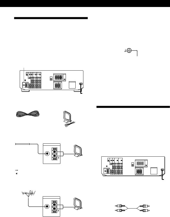
Antenna Hookups
Overview
This section describes how to connect AM and FM antennas to the receiver. If you want to receive radio broadcasts with the receiver, complete these connections first, then go to the following pages. For specific locations of the terminals, see the illustration below.
ANTENNA
What antennas will I need?
• FM wire antenna |
• AM loop antenna |
(supplied) (1) |
(supplied) (1) |
Hookups
FM wire antenna |
Receiver |
AM loop antenna |
|
|
ANTENNA |
|
|
After connecting |
FM |
|
|
75Ω |
AM |
||
the wire antenna, |
COAXIAL |
||
|
|||
|
|
||
keep it as horizontal |
|
|
|
as possible. |
|
|

 If you have poor FM reception
Connect a 75-ohm coaxial cable (not supplied) to an FM outdoor antenna.
FM outdoor antenna
Receiver
ANTENNA
FM |
|
|
75Ω |
AM |
|
COAXIAL |
||
|
Connecting a ground wire
To prevent hum, connect a ground wire (not supplied) to the y ground terminal. If you’ve connected an outdoor antenna, be sure to connect the ground for lightning protection.
Receiver
.
to ground
Where do I go next?
If you want to connect other components, go on to the next section. If you’re only planning to use the receiver to listen to the radio, go to “Speaker System Hookups” on pages 6 and 7.
Audio Component Hookups
Overview
This section describes how to connect your audio components to the receiver. If you want to use the receiver as an amplifier, complete these connections. For specific locations of the jacks, see the illustration below.
S-LINK CTRL A1 jack |
TAPE |
|
|
||||||||||||||||||||||||
|
|
|
|
|
|
|
|
|
|
|
|
|
|
|
|
|
|
|
|
|
|
|
|
|
|
|
|
|
|
|
|
|
|
|
|
|
|
|
|
|
|
|
|
|
|
|
|
|
|
|
|
|
|
|
|
|
|
|
|
|
|
|
|
|
|
|
|
|
|
|
|
|
|
|
|
|
|
|
|
|
|
|
|
|
|
|
|
|
|
|
|
|
|
|
|
|
|
|
|
|
|
|
|
|
|
|
|
|
|
|
|
|
|
|
|
|
|
|
|
|
|
|
|
|
|
|
|
|
|
|
|
|
|
|
|
|
|
|
|
|
|
|
|
|
|
|
|
|
|
|
|
|
|
|
|
|
|
|
|
|
|
|
|
|
|
|
|
|
|
|
|
|
|
|
|
|
|
|
|
|
|
|
|
|
|
|
|
|
|
|
|
|
|
|
|
|
|
|
|
|
|
|
|
|
|
|
|
|
|
|
|
|
|
|
|
|
|
|
|
|
|
|
|
|
|
|
|
|
|
|
|
|
|
|
|
|
|
|
|
|
|
|
|
|
|
|
|
|
|
|
|
PHONO CD DAT/MD
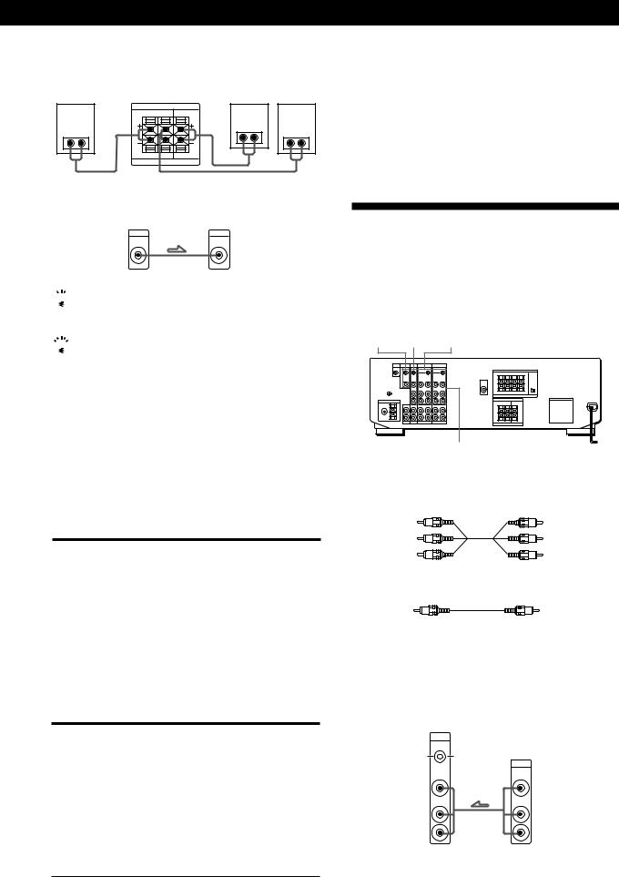
What cords will I need?
Audio cords (not supplied) (1 for each CD player and turntable; 2 for each tape deck, DAT deck, or MD deck)
White (L) |
White (L) |
Red (R) |
Red (R) |
(continued)
5EN

Getting Started
Hookups
The arrow •indicates signal flow.
CD player |
|
CD player |
|
Receiver |
|||
|
IN |
OUTPUT |
|
|
|
LINE |
|
L |
|
|
|
|
|
|
L |
R |
|
|
|
|
|
|
R |
|
CD |
|
|
Tape deck |
|
|
|
Receiver |
Tape deck |
||
REC OUT |
IN |
OUTPUT |
INPUT |
L |
|
LINE |
LINE |
|
|
|
L |
R |
|
|
|
TAPE MONITOR |
|
R |
|
|
|
||
DAT/MD |
|
|
|
Receiver |
DAT/MD |
||
REC OUT |
IN |
OUTPUT |
INPUT |
L |
|
LINE |
LINE |
|
|
|
L |
R |
|
|
|
DAT/MD |
|
R |
|
|
|
||
Turntable |
|
Turntable |
|
Receiver |
|||
|
IN |
OUTPUT |
|
LINE
L
L
R
R
PHONO
•If your turntable has an earth lead
To prevent hum, connect the earth lead to the yground terminal on the receiver.
CONTROL A1 Hookups (USA and Canadian STR-DE705 only)
•If you have a CONTROL A1 compatible Sony CD player or tape deck
Use a CONTROL A1 cord (not supplied) to connect the S-LINK CTRL A1 jack on the CD player or tape deck to the S-LINK CTRL A1 jack on the receiver. Refer the separate manual “CONTROL-A1 Control System” and the Operating Instructions supplied with your CD player or tape deck for details.
•If you have a Sony CD changer with a COMMAND MODE selector
If the CD changer’s COMMAND MODE selector can be switched between CD 1, CD 2, and CD 3, be sure to set the command mode to “CD 1” and connect the changer to the CD terminals on the receiver.
However, if you have a Sony CD changer with VIDEO OUT terminals, set the command mode to “CD 2” and connect the changer to the VIDEO 2 terminals on the receiver.
Where do I go next?
Speaker System Hookups
Overview
This section describes how to connect your speakers to the receiver. Although front (left and right) speakers are required, center and rear speakers are optional. Adding center and rear speakers will enhance the surround effects. Connecting an active woofer will increase bass response.
For specific locations of the terminals, see the illustration below.
IMPEDANCE MIX OUT FRONT SPEAKERS A SELECTOR
|
|
|
|
|
|
|
|
|
|
|
|
|
|
|
|
|
|
|
|
|
|
|
|
|
|
|
|
|
|
|
|
|
|
|
|
|
|
|
|
|
|
|
|
|
|
|
|
|
|
|
|
|
|
|
|
|
|
|
|
|
|
|
|
|
|
|
|
|
|
|
|
|
|
|
|
|
|
|
|
|
|
|
|
|
SURROUND |
|
SURROUND |
||||||||
|
SPEAKERS REAR |
|
SPEAKERS CENTER |
||||||||
For optimum surround sound effect, place your speakers as shown below.
Rear speaker
60 - 90 cm 

45°
Front speaker
What cords will I need?
Speaker cord (not supplied) (1 for each speaker)
(+) |
(+) |
(–) |
(–) |
|
Twist the stripped ends of the cord about 2/3 inch (15 mm). Be sure to match the speaker cord to the appropriate terminal on the components: + to + and – to –. If the cords are reversed, the sound will be distorted and will lack bass.
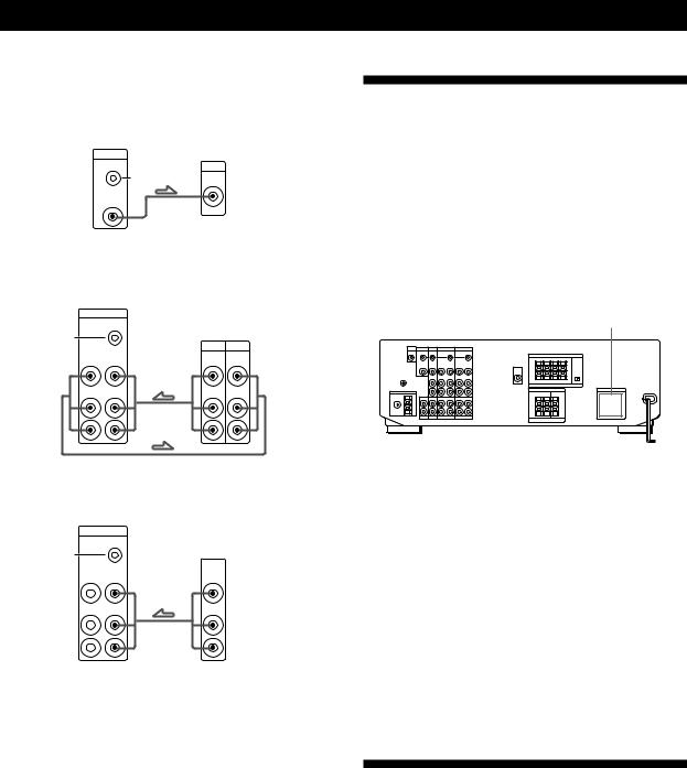
Hookups
Front speakers
Front speaker
(R)
}]
Receiver
Front speaker
(L)
FRONT SPEAKERS |
|
R |
L |
A |
A |
|
}] |
IMPEDANCE USE 4-16 Ω |
|
6EN |
Go on to the next section to connect the speakers. |
Rear and center speakers
Rear speaker |
|
Rear speaker |
(R) |
Receiver |
Center speaker (L) |
SURROUND SPEAKERS |
|
|
R REAR L |
CENTER |
|
} ] |
} ] |
} ] |
|
||
R L |
|
|
IMPEDANCE USE 8-16 Ω |
|
|
Active woofer
Receiver |
Active woofer |
MIX |
INPUT |
AUDIO |
|
OUT |
|

 If you have an additional front speaker system
Connect them to the FRONT SPEAKERS B terminals.
 If your TV monitor uses separate speakers
You can connect one of them to the SURROUND SPEAKER CENTER terminals for use with Dolby Pro Logic Surround Sound (see page 18).
Selecting the impedance (STR-DE705 and STR-D650Z only)
Set the IMPEDANCE SELECTOR for the front speakers as indicated in the table below. Check the instruction manual of your speakers if you’re not sure of the impedance. (This information is usually printed on a label on the back of the speaker.)
if nominal impedance of |
Set IMPEDANCE SELECTOR to |
your speaker is |
|
|
|
Between 4 and 8 ohms |
4 Ω |
|
|
8 ohms or higher |
8 Ω |
|
|
Getting Started
Where do I go next?
To complete your system, go to “AC Hookups” on page 8. If you want to connect video components to enjoy surround sound when watching TV programs or video tapes, go on to the next section.
TV/VCR Hookups
Overview
This section describes how to connect video components to the receiver. For specific locations of the jacks, see the illustration below.
MONITOR TV VIDEO 2
VIDEO 1
What cables will I need?
•Audio/video cable (not supplied) (1 for each TV or LD player; 2 for each VCR)
Yellow |
Yellow |
White (L) |
White (L) |
Red (R) |
Red (R) |
• Video cable (not supplied) (1 for a TV monitor)
Yellow |
Yellow |
Selecting the speaker system
If you connect only one set of front speakers, set the SPEAKERS selector on the front panel to A. If you connect two sets of front speakers, see the following:
To drive |
Set SPEAKERS selector to |
|
|
Speaker system A (connected |
A |
to the FRONT SPEAKERS A |
|
terminals) |
|
|
|
Speaker system B (connected |
B |
to the FRONT SPEAKERS B |
|
terminals) |
|
|
|
Both speaker systems A and |
A+B* |
B (parallel connection) |
|
*Do not use A+B with SOUND FIELD set to ON.
Hookups
The arrow •indicates signal flow.
TV or Digital Broadcasting System (DBS) tuner
Receiver |
TV |
TV/DBS |
or |
CTRL S |
DBS tuner |
STATUS IN |
|
|
OUTPUT |
VIDEO |
VIDEO |
IN |
|
AUDIO |
AUDIO |
IN |
|
L |
L |
R |
R |
(continued)
7EN
Getting Started
TV monitor
If you use a TV monitor, do not connect anything to the TV/DBS VIDEO IN jack.
Receiver |
TV monitor |
MONITOR |
|
CTRL S |
INPUT |
IN |
|
|
VIDEO |
VIDEO |
|
OUT |
|
VCR (via the VIDEO 1 jacks)
If you have two VCRs connect the second one to the VIDEO 2 jacks.
Receiver
VIDEO 1
|
CTRL S |
|
|
|
|
OUT |
VCR |
||
S-LINK |
|
|||
|
|
OUTPUT |
INPUT |
|
VIDEO |
VIDEO |
VIDEO |
VIDEO |
|
OUT |
IN |
|||
AUDIO |
AUDIO |
AUDIO |
AUDIO |
|
OUT |
IN |
|||
|
|
|||
L |
|
|
L |
|
R |
|
|
R |
|
LD player (via the VIDEO 2 jacks)
Receiver
VIDEO 2
|
CTRL S |
|
|
|
OUT |
LD |
|
S-LINK |
|
||
|
|
OUTPUT |
|
VIDEO |
VIDEO |
VIDEO |
|
OUT |
IN |
||
AUDIO |
AUDIO |
AUDIO |
|
OUT |
IN |
||
|
|||
L |
|
L |
|
R |
|
R |
•If you have a CONTROL S compatible Sony TV, DBS tuner, monitor, VCR or LD player (USA and Canadian STR-DE705 only)
Use a CONTROL S cord (supplied) to connect the S-LINK CTRL S IN (for TV, DBS tuner, or monitor) or OUT (for VCR or LD player) jack on the receiver to the appropriate S-LINK jack on the respective component. Refer to the Operating Instructions supplied with your TV, DBS tuner, monitor, VCR, or LD player for details.
Where do I go next?
Go on to the next section to connect an AC plug and complete your home theater system.
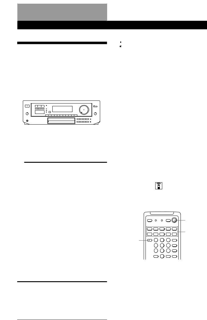
AC Hookups
Connecting the AC power cord
Connect the AC power cord from this receiver and from your audio/video components to a wall outlet. If you connect other audio components to the SWITCHED AC OUTLETs on the receiver, the receiver can supply power to the connected components so you can turn on/off whole system when you turn on/off the receiver.
SWITCHED AC OUTLETs
/
to a wall outlet
Caution
Make sure that the power consumption of the component(s) connected to the receiver’s AC outlet(s) does not exceed the wattage stated on the rear panel. Do not connect highwattage electrical home appliances such as electric irons, fans, or TVs to this outlet.
Where do I go next?
Before you use theÊ receiver, go to the next section to make sure that all the controls are set to the appropriate positions.
Before You Use Your Receiver
Before you start using your receiver, make sure that you have:
•Turned MASTER VOLUME to the leftmost position (0).
•Selected the appropriate speaker system. (For details, see “Selecting the speaker system” on page 7.)
•Set BALANCE to the center position.
Turn on the receiver and check the following indicator.
•Press MUTING on the remote if MUTING appears in the display.
8EN
Receiver Operations
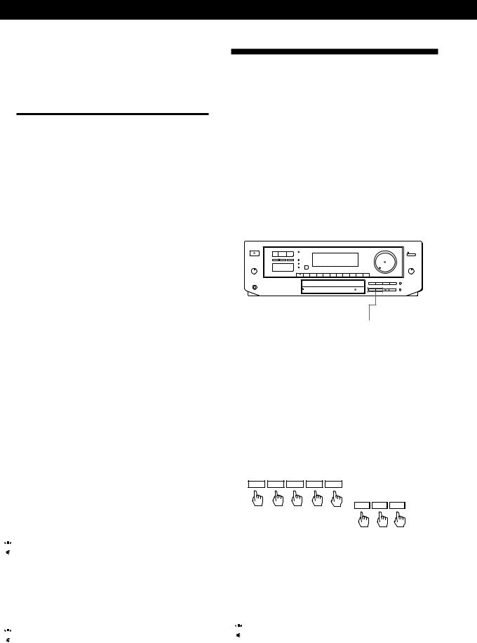
Selecting a Component
To listen to or watch a connected component, first select the function on the receiver or with the remote. Before you begin, make sure you have:
•Connected all components securely and correctly as indicated on pages 5 to 8.
•Turned MASTER VOLUME to the leftmost position
(0) to avoid damaging your speakers.
POWER |
|
|
|
|
|
|
MASTER VOLUME |
|||||||||||
|
|
|
|
|
|
|
|
|
|
|
|
|
|
|
|
|
|
|
|
|
|
|
|
|
|
|
|
|
|
|
|
|
|
|
|
|
|
|
|
|
|
|
|
|
|
|
|
|
|
|
|
|
|
|
|
|
|
|
|
|
|
|
|
|
|
|
|
|
|
|
|
|
|
|
|
|
|
|
|
|
|
|
|
|
|
|
|
|
|
|
|
|
|
|
|
|
|
|
|
|
|
|
|
|
|
|
|
|
|
|
|
|
|
|
|
|
|
|
|
|
|
|
|
|
|
|
|
|
|
|
|
|
|
|
|
|
|
|
|
|
|
|
|
|
|
|
|
|
|
|
|
|
|
|
|
|
|
|
|
|
|
|
|
|
|
|
|
|
|
|
Function buttons
1Press POWER to turn on the receiver.
2Press a function button to select the component you want to use:
To listen to or watch |
Press |
|
|
Records |
PHONO |
|
|
Radio programs |
TUNER |
|
|
Compact Discs (CD) |
CD |
|
|
Digital Audio Tapes (DAT) |
DAT/MD |
or MiniDiscs (MD) |
|
|
|
Audio tapes |
TAPE MONITOR |
|
|
TV programs |
TV/DBS |
|
|
Video tapes |
VIDEO 1 or |
|
VIDEO 2 |
|
|
Laser discs |
VIDEO 2 |
|
|
3Turn on the component, for example, a CD player, and then start playing.
To tune in radio stations on this receiver, see “Receiving Broadcasts” on page 10.
4Turn MASTER VOLUME to adjust the volume. To adjust the volume of the TV's speakers, use the volume control on the TV.
To |
Do This |
|
|
Mute the sound |
Press MUTING on the remote. |
|
Press again to restore the sound. |
|
|
Reinforce the bass |
Press BASS BOOST to turn on |
|
the BASS BOOST indicator |
|
|
Adjust the balance |
Turn the BALANCE control left |
|
or right. |
Receiver Operations
 When you listen with headphones
Connect the headphones to the PHONES jack and set the SPEAKERS selector to OFF.
Watching video programs
When you watch TV or video programs, we recommend you play audio portion through the receiver instead of your TV’s speaker. This lets you take advantage of the receiver’s surround sound effects, like Dolby Surround, and lets you use the receiver’s remote to control the audio.
Turn off the speakers on your TV before you start so you can enjoy the surround sound from your receiver.
To watch TV programs, turn on both the TV and the receiver and press the TV button on the receiver.
To watch videos or laser discs, do the following:
1Press a function button to select the component (for example, VIDEO 1).
2Turn on the TV and set the TV’s video input to match your video component.
3Turn on the component (VCR or LD player), and start playback.
Using the remote
The remote lets you operate the receiver and the Sony components that are connected to it.
|
SYSTEM |
|
OFF |
|
SYSTEM |
|
CONTROL/ |
TV CONTROL |
FUNCTION |
ON |
|

(continued)
9EN
Receiver Operations
1Press one of the SYSTEM CONTROL/FUNCTION buttons to select the component you want to use. The receiver and the selected component turn on. The SYSTEM CONTROL/FUNCTION buttons on the remote are factory-set as follows:
To listen to or watch |
Press |
|
|
Records |
PHONO |
|
|
Radio programs |
TUNER |
|
|
Compact Discs (CD) |
CD |
|
|
Digital Audio Tapes (DAT) |
DAT/MD |
or MiniDiscs (MD) |
|
|
|
Audio tapes |
TAPE |
|
|
TV programs |
TV/DBS |
|
|
Video tapes |
VIDEO 1 (VTR 1*), |
|
VIDEO 2 (VTR 2*) or |
|
VIDEO 3** (VTR 3*) |
|
|
Laser discs |
LD** |
|
|
*Sony VCRs are operated with a VTR 1, 2, or 3 setting that correspond to VHS, Beta, and 8mm respectively.
**VIDEO 3 and LD set the remote to operate the respective Sony video component but do not switch the function of the receiver.
For example, to watch Sony LD player connected to the VIDEO 2 terminals (as shown on page 8):
Press VIDEO 2 to switch the function, then press LD to set the remote control to operate the LD player.
If you want to change the factory setting of a button
See page 20.
If the component does not turn on
Press the power switch on the component.
2Start playing.
Refer to “Remote Button Descriptions” on page 27 for details.
To turn off the components
Press SYSTEM OFF. This will also turn off the video and audio components connected to the SWITCHED AC OUTLETs on the back of this unit at the same time.

 If you use a Sony TV
When you press TV to watch a TV program, the TV turns on and switches to the TV input. The TV also turns on automatically and switches to the appropriate video input when you press VIDEO 1 or VIDEO 2. If the TV does not switch to the appropriate input automatically, press TV/VIDEO on the remote.

 Watching TV without the receiver (for Sony TVs only)
Press TV CONTROL ON to set the remote to operate TV functions only (see “Remote Button Descriptions” on page 27 for details). When you press this button, the TV turns on and switches to the TV input. If the TV does
not automatically switch to the TV input, press TV/ 10EN VIDEO.
Receiving Broadcasts
This receiver lets you enter a station’s frequency directly by using the numeric buttons (direct tuning). If you don’t know the frequency of the station you want, see “Receiving broadcasts by scanning stations (automatic tuning)”.
Before you begin, make sure you have:
•Connected an FM/AM antenna to the receiver as indicated on page 5.
•Selected the appropriate speaker system. (For details, see “Selecting the speaker system” on page 7.)
POWER |
|
|
|
Number buttons MASTER VOLUME |
|||||||||||||||||
|
|
|
|
|
|
|
|
|
|
|
|
|
|
|
|
|
|
|
|
|
|
|
|
|
|
|
|
|
|
|
|
|
|
|
|
|
|
|
|
|
|
|
|
|
|
|
|
|
|
|
|
|
|
|
|
|
|
|
|
|
|
|
|
|
|
|
|
|
|
|
|
|
|
|
|
|
|
|
|
|
|
|
|
|
|
|
|
|
|
|
|
|
|
|
|
|
|
|
|
|
|
|
|
|
|
|
|
|
|
|
|
|
|
|
|
|
|
|
|
|
|
|
|
|
|
|
|
|
|
|
|
|
|
|
|
|
|
|
|
|
|
|
|
|
|
|
|
|
|
|
|
|
|
|
|
|
|
|
|
|
|
|
|
|
|
|
|
|
|
|
|
|
|
|
|
|
|
|
|
|
|
|
|
|
|
|
|
|
|
|
|
|
|
|
|
|
|
DIRECT |
TUNER FM/AM |
|
TUNING/ |
|
– INDEX SELECT + |
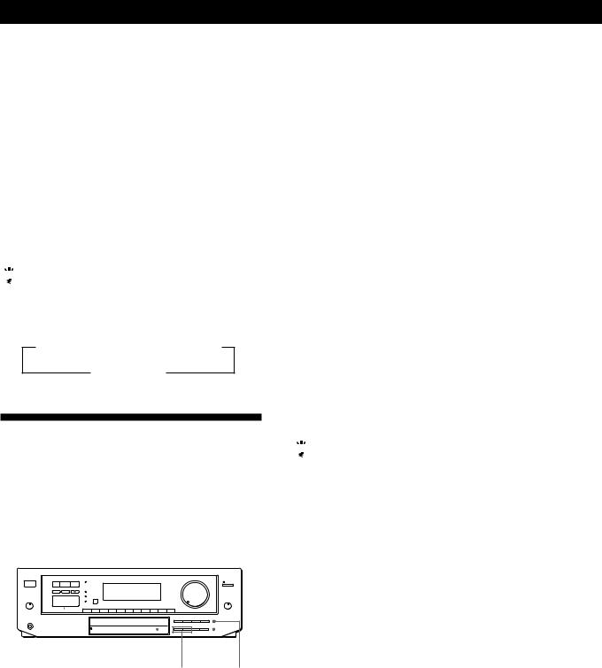
1Press POWER to turn on the receiver.
2Press TUNER.
The last received station is tuned in.
3Press FM/AM to select FM or AM stations.
4Press DIRECT.
5Press the numeric buttons to enter the frequency.
Example 1:FM 102.50 MHz |
Example 2:AM 1350kHz |
||||||
1 |
0 |
2 |
5 |
0 |
(You don’t have to enter |
||
|
|
|
|
|
the last “0.”) |
||
|
|
|
|
|
1 |
3 |
5 |
6When you tune in AM stations, adjust the direction of the AM loop antenna for optimum reception.
To receive other stations
Repeat Steps 3 to 5.

 If the STEREO indicator remains off
Press FM MODE even when an FM stereo broadcast is received.
Receiver Operations

 If an FM stereo program is distorted
The STEREO indicator flashes. Press FM MODE to change to monaural (MONO). You will not have the stereo effect but the distortion will be reduced. To return to the auto stereo mode, press this button again.

 If you cannot tune in a station and the entered numbers are flashing
Make sure you’ve entered the right frequency. If not, press DIRECT and reenter the frequency you want. If the entered numbers still flash, the frequency is not used in your area.

 To watch FM simulcast TV programs
Make sure that you tune in the simulcast program on both the TV (or VCR) and the receiver.

 If you enter a frequency not covered by the tuning interval
The entered value is automatically rounded up or down to the closest covered value.
Tuning intervals for direct tuning are: FM: 50 kHz intervals
AM: 10 kHz intervals (to change to 9 kHz intervals, see page 23)
Receiving broadcasts by scanning stations (automatic tuning)
If you don’t know the frequency of the radio station you want, you can have the receiver scan all the receivable stations to locate the one you want.
1Press TUNER.
The last received station is tuned in.
2Press DISPLAY so that the frequency appears in the display.
3Press FM/AM to select FM or AM.
4Press TUNING/INDEX SELECT + or –.
Press the + button for a higher station number; press the – button for a lower one. When you tune past either end of the band, the receiver automatically jumps to the opposite end and continues scanning in the same direction. Every time a station is received, the receiver stops scanning. To continue scanning, press the button again.

 If scanning stops too frequently (for FM band only)
Skip the stations with weak signals. Press LEVEL. “HIGH” appears in the display and the receiver scans only stations with strong signals.
Presetting Radio Stations
You’ll most likely want to preset the receiver with the radio stations you listen to often so that you don’t have to tune in the station every time. The receiver can store a total of 30 FM or AM stations. You can store the stations on preset numbers combining 3 characters (A, B and C) and numbers (0-9). For example, you can store a station as preset number A1, B6, or C9.
|
|
|
|
|
|
|
Numeric buttons |
|
SHIFT |
||||||||||||
|
|
|
|
|
|
|
|
|
|
|
|
|
|
|
|
|
|
|
|
|
|
|
|
|
|
|
|
|
|
|
|
|
|
|
|
|
|
|
|
|
|
|
|
|
|
|
|
|
|
|
|
|
|
|
|
|
|
|
|
|
|
|
|
|
|
|
|
|
|
|
|
|
|
|
|
|
|
|
|
|
|
|
|
|
|
|
|
|
|
|
|
|
|
|
|
|
|
|
|
|
|
|
|
|
|
|
|
|
|
|
|
|
|
|
|
|
|
|
|
|
|
|
|
|
|
|
|
|
|
|
|
|
|
|
|
|
|
|
|
|
|
|
|
|
|
|
|
|
|
|
|
|
|
|
|
|
|
|
|
|
|
|
|
|
|
|
|
|
|
|
|
|
|
|
|
|
|
|
|
|
|
|
|
|
|
|
|
|
|
|
|
|
|
|
|
|
|
TUNER MEMORY
1Press TUNER.
The last received station is tuned in.
2Tune in the station you want.
If you are not familiar with how to tune in a station, see “Receiving Broadcasts” on the previous page.
3Press MEMORY.
“MEMORY” appears for a few seconds.
Do steps 4 and 5 before “MEMORY” goes out.
4Press SHIFT to select a memory page (A, B or C). Each time you press SHIFT, the letter “A”, “B” or “C” appear in the display.
5Press the number you want to use (0 to 9).
If “MEMORY” goes out before you specify the preset number, start again from step 3.
6Repeat steps 2 to 5 to preset other stations.
To change a preset station
Preset a new station on the number you want to change.
Note
If the AC power cord is disconnected for about one week, the preset stations will be cleared from the receiver’s memory, and you will have to preset the stations again.
(continued)
11EN
Receiver Operations
Tuning preset stations (preset tuning)
You can tune directly to a preset station by entering its preset number. If you don’t know which stations are preset on which numbers, you can tune by scanning the preset stations.
1Press TUNER.
The last received station is tuned in.
2Press SHIFT to select a memory page (A, B or C), then press the number.
For example, select A and then press 7 to tune in the station preset as A7.

 You can tune by scanning the preset stations
Press TUNER and then DISPLAY so that the frequency display appears. Then press PRESET TUNING + or – to select the station you want. Each time you press the buttons, the preset numbers change as follows:
nA1÷A2÷...÷A0÷B1÷B2÷...÷B0N
nC0÷...C2÷C1N
Indexing
You can index preset stations and then use the index names to scan specific stations in the preset memory. You can also use the index feature to label program sources so that the receiver displays the names of the components you connected, for example, “VHS”.
|
|
|
|
|
DPC MODE |
PRESET TUNING +/– |
|||||||||||||||||
|
|
|
|
|
|
|
|
|
|
|
|
|
|
|
|
|
|
|
|
|
|
|
|
|
|
|
|
|
|
|
|
|
|
|
|
|
|
|
|
|
|
|
|
|
|
|
|
|
|
|
|
|
|
|
|
|
|
|
|
|
|
|
|
|
|
|
|
|
|
|
|
|
|
|
|
|
|
|
|
|
|
|
|
|
|
|
|
|
|
|
|
|
|
|
|
|
|
|
|
|
|
|
|
|
|
|
|
|
|
|
|
|
|
|
|
|
|
|
|
|
|
|
|
|
|
|
|
|
|
|
|
|
|
|
|
|
|
|
|
|
|
|
|
|
|
|
|
|
|
|
|
|
|
|
|
|
|
|
|
|
|
|
|
|
|
|
|
|
|
|
|
|
|
|
|
|
|
|
|
|
|
|
|
|
|
|
|
|
|
|
|
|
|
|
|
|
|
|
|
|
|
|
|
|
|
|
|
|
|
|
|
|
|
|
|
Digital |
TUNER MEMORY |
|
processing |
TUNING/ DISPLAY |
|
control buttons |
||
|
INDEX SELECT +/–
Indexing preset stations
You might find that too many preset stations make it hard to find the station you want. This receiver includes a feature that lets you group preset stations by name (station index) using up to 8 characters.
For example, if you label all of your preset jazz stations “JAZZ,” selecting “JAZZ” lets you skip other presets and scan only the stations labeled “JAZZ.” Note that you cannot assign more than one station index name to each preset station.
1Press TUNER.
The last station you received is tuned in.
2Tune in the preset station you want to create an index for.
If you are not familiar with how to tune in preset stations, see “Tuning preset stations (preset tuning)” above.
3Press DPC MODE repeatedly until the INDEX indicator lights up.
4Create a station index name by using the digital processing control buttons as follows:
Press or
or to select a character, and then
press to move the cursor to the next position.
To insert a space, press or
or until a blank space appears in the display (the space is between “}” and “!”).
The station index is stored automatically.
If you’ve made a mistake
Press or
or repeatedly until the character you want to change flashes. Then select the right character.
5Repeat Steps 2 to 4 to assign index names to other stations.

 You can display either the index name or frequency
Each time you press DISPLAY, the display switches between the frequency and the index name.
Scanning indexed stations (index tuning)
Once you select a station index, you can scan all the stations with that station index.
1Press TUNER.
The last station you received is tuned in.
2Press DISPLAY so that the index mode appears in the display.
The station index for the last station you received appears in the display.
If “_ _ _ _ ” appears
The station does not have a station index.
3Press TUNING/INDEX SELECT + or – to select the station index you want to scan.
4Press PRESET TUNING + or – to select the station you want receive.
To select different station indexes
Press TUNING/INDEX SELECT + or – to select the one you want, then press PRESET TUNING + or – to select a station.
12EN

Receiver Operations
Indexing program sources
This feature is useful when, for example, you have more than one VCR: you can label one VCR as “VHS” and label the other as “8MM.” Then, you can have the receiver display the index names so you can tell which VCR you are using. This feature also comes in handy if you connect a component to jacks designed for another component (for example, connecting a second CD player to the DAT/MD jacks).
1Press the FUNCTION button you want to label.
2Press DPC MODE repeatedly until the INDEX indicator lights up.
3Create a name by using the digital processing control buttons as follows:
Press or
or to select a character, and then
press to move the cursor to the next position.
To insert a space, press or
or until a blank space appears in the display (the space is between “}” and “!”).
The name you created is stored automatically.
If you’ve made a mistake
Press or
or repeatedly until the character you want to change flashes. Then select the right character.

 You can display either the index or function name
Each time you press DISPLAY, the display switches between the function name and the index name.
Recording
This receiver makes it easy to record to and from the components connected to the receiver. You don’t have to connect playback and recording components directly: once you select a program source on the receiver, you can record and edit as you normally would using the controls on each component.
Before you begin, make sure you’ve connected all components properly.
|
|
|
|
|
|
c |
|
|
|
|
|
|
|
|
|
|
|
|
|
|
|
|
|
|
|
|
|
|
|
|
|
|
|
|
|
|
|
|
|
|
|
||
|
|
|
• |
|
|
|
|
|
|
|
|
• |
c |
||||||||
|
|
|
|
Function buttons |
|||||||||||||||||
|
|
|
|
|
|
|
|
|
|
|
|
|
|
||||||||
|
|
|
|
|
|
|
|
|
|
|
|
|
|
|
|
|
|
|
|
|
|
|
Playback component |
|
|
|
Recording component |
||||||||||||||||
|
(program source) |
|
|
|
(tape deck, DAT deck, |
||||||||||||||||
|
|
|
|
|
|
|
|
|
|
|
|
|
MD deck, VCR) |
||||||||
•: Audio signal flow |
|||||||||||||||||||||
|
|
|
|
|
|
|
|
|
|
|
|||||||||||
|
|
|
|
|
|
|
|
|
|
|
|||||||||||
c: Video signal flow |
|
|
|
|
|
|
|
|
|
|
|
||||||||||
Recording on an audio tape or MiniDisc
You can record on a cassette tape, Digital Audio Tape or MiniDisc using the receiver. See the instruction manual of your cassette deck, DAT deck, or MD deck if you need help.
1Press one of the function buttons to select the component to be recorded.
2Set the component to be ready for playing. For example, insert a CD into the CD player.
3Insert a blank tape into the recording deck and adjust the recording level, if necessary.
4Start recording on the recording deck and then start playing the component.
You can monitor the sound being recorded
If you connected a 3-head tape deck to the TAPE MONITOR jacks, press TAPE MONITOR. The TAPE MONITOR indicator lights up and you can hear the sound being recorded.
Note
When you record on a DAT or MD connected to the DAT/ MD REC OUT jacks, sound adjustments do not effect the recording.
(continued)
13EN

Receiver Operations
Recording on a video tape
You can record from a VCR, a TV, or an LD player using the receiver. You can also add audio from a variety of audio sources when editing a video tape. See your VCR or LD player’s instruction manual if you need help.
1Press one of the function buttons to select the program source to be recorded.
2Set the component to be ready for playing. For example, insert the laser disc you want to record from into the LD player.
3Insert a blank video tape into the VCR (VIDEO 1 or VIDEO 2) for recording.
4Start recording on the recording VCR and then start playing the video tape or laser disc you want to record.

 You can replace audio while copying a video tape or laser disc
At the point you want to start adding different sound, press another function button (for example, CD) and start playback. The sound from the selected component will be recorded over the original audio.
To resume recording the sound of the original playback source, press the function button for that component.
Using the Sleep Timer 


You can set the receiver to turn off automatically at a time you specify.
SLEEP

Press SLEEP on the remote while the power is on. Each time you press SLEEP, the time changes as shown below.
n2:00:00 n1:30:00n1:00:00 n0:30:00 nOFF
The display dims after you specify the time.
You can freely specify the time
Press SLEEP first, then specify the time you want using the digital processing control ( or
or ) buttons. The sleep time changes in 1 minute intervals. You can specify up to 5 hours.

 You can check the time remaining before the receiver turns off
Press SLEEP. The remaining time appears in the display.
14EN
|
|
|
|
Using Surround Sound |
Using Surround Sound |
|
|
|
Using Pre-programmed Sound
Fields
You can take advantage of surround sound simply by selecting one of the pre-programmed sound fields according to the program you want to play. (STR-D550Z sound fields are shown on the next page.)
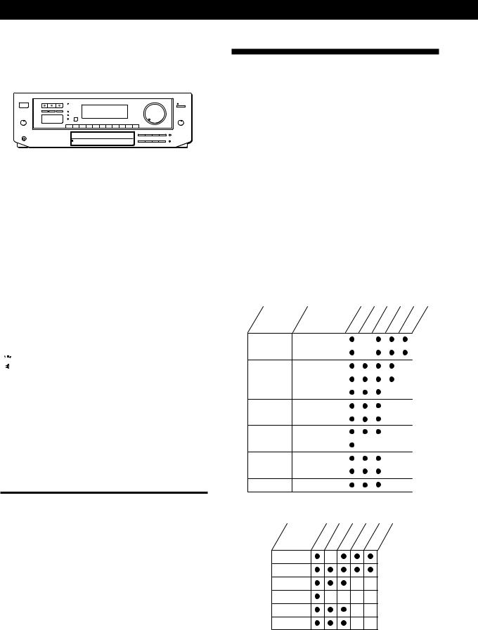
STR-DE705/STR-DE605/STR-D650Z
SOUND FIELD
ON/OFF
GENRE MODE
1Press SOUND FIELD ON/OFF to turn on the sound field.
One of the indicators lights up in the display.
2Press GENRE to select the type of sound field you desire.
3Press MODE to select the mode you desire from the respective genre.
Select the appropriate sound field according to the chart shown at right.
To play without surround effects
Select “Acoustic” from MUSIC 2. The surround effects are defeated but you can still adjust the tone parameter (see page 17).
To turn off the sound fields
Press SOUND FIELD ON/OFF.
You can find Dolby Surround-encoded software by looking at the packaging
However, some videos and laser discs may use Dolby Surround sound even if it's not indicated on the package.
Note
Make sure to select both speakers (A+B) with the SPEAKERS selector when you use two sets of speakers; otherwise, you will not obtain the full surround effect.
Sound Fields for STR-DE705/STR-DE605/STR-D650Z
GENRE |
MODE |
To |
|
|
|
PRO LOGIC |
PRO LOGIC |
Decode programs |
|
|
processed with Dolby |
|
|
Surround. |
|
|
|
|
ENHANCED |
Provide additional |
|
|
output to the rear |
|
|
speakers after |
|
|
decoding the Dolby |
|
|
Surround program |
|
|
|
MOVIE |
SMALL THEATER |
Add the acoustic |
|
|
reflections of a small |
|
|
theater to decoded |
|
|
Dolby Surround |
|
|
signals. |
|
|
|
|
LARGE THEATER |
Add the reflections of |
|
|
a larger theater. |
|
|
|
|
MONO THEATER |
Create a theater-like |
|
|
environment from |
|
|
movies with monaural |
|
|
soundtracks. |
|
|
|
MUSIC 1 |
SMALL HALL |
Reproduce the |
|
|
acoustics of a small |
|
|
rectangular concert |
|
|
hall. Ideal for soft |
|
|
acoustic sounds. |
|
|
|
|
LARGE HALL |
Reproduce the |
|
|
acoustics of a larger |
|
|
hall. |
|
|
|
MUSIC 2 |
KARAOKE |
Reduce the vocals of a |
|
|
stereo music source. |
|
|
|
|
ACOUSTIC |
Reproduce normal 2 |
|
|
channel stereo. |
|
|
(No surround effects) |
|
|
|
SPORTS |
ARENA |
Reproduce the feeling |
|
|
of being in the front |
|
|
row of a large concert |
|
|
arena. Great for Rock |
|
|
and Roll. |
|
|
|
|
STADIUM |
Reproduce the feeling |
|
|
of a large open-air |
|
|
stadium. Great for |
|
|
electric sounds. |
|
|
|
GAME |
– |
Obtain maximum |
|
|
audio impact from |
|
|
video game software. |
|
|
|
15EN
Using Surround Sound
STR-D550Z
|
|
|
|
|
|
|
|
|
|
|
SOUND FIELD |
|
|
|
|
|||
|
SOUND FIELD </> |
|
ON/OFF |
|
|
|
|
|||||||||||
|
|
|
|
|
|
|
|
|
|
|
|
|
|
|
|
|
|
|
|
|
|
|
|
|
|
|
|
|
|
|
|
|
|
|
|
|
|
|
|
|
|
|
|
|
|
|
|
|
|
|
|
|
|
|
|
|
|
|
|
|
|
|
|
|
|
|
|
|
|
|
|
|
|
|
|
|
|
|
|
|
|
|
|
|
|
|
|
|
|
|
|
|
|
|
|
|
|
|
|
|
|
|
|
|
|
|
|
|
|
|
|
|
|
|
|
|
|
|
|
|
|
|
|
|
|
|
|
|
|
|
|
|
|
|
|
|
|
|
|
|
|
|
|
|
|
|
|
|
|
|
|
|
|
|
|
|
|
|
|
|
|
|
|
|
|
|
|
|
|
|
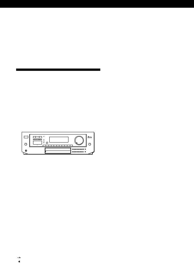
1Press SOUND FIELD ON/OFF to turn on the sound field.
One of the indicators lights up in the display.
2Press SOUND FIELD < or > repeatedly to select the sound field you desire.
Select the appropriate sound field according to the chart shown below.
To play without surround effects
Select MUSIC 2. The surround effects are defeated but you can still adjust the tone parameter (see page 17).
To turn off the sound fields
Press SOUND FIELD ON/OFF.

 You can find Dolby Surround-encoded software by looking at the packaging
However, some videos and laser discs may use Dolby Surround sound even if it's not indicated on the package.
Note
Make sure to select both speakers (A+B) with the SPEAKERS selector when you use two sets of speakers; otherwise, you will not obtain the full surround effect.
Sound Fields for STR-D550Z
Select |
To |
|
|
PRO LOGIC |
Decode programs processed with Dolby |
|
Surround. |
|
|
MOVIE |
Add the acoustic reflections of a movie |
|
theater to decoded Dolby Surround |
|
signals. |
|
|
MUSIC 1 |
Reproduce the acoustics of a small |
|
rectangular concert hall. Ideal for soft |
|
acoustic sounds. |
|
|
MUSIC 2 |
Reproduce normal 2 channel stereo. |
|
(No surround effects) |
|
|
SPORTS |
Reproduce the feeling of a large open-air |
|
stadium. Great for sporting events or |
|
electric sounds. |
|
|
GAME |
Obtain maximum audio impact from video |
|
game software. |
|
|
Taking Advantage of the
Sound Fields
How can you customize the sound fields?
Each sound field is composed of sound parameters — variables of sound that create sound image. You can customize the sound fields by adjusting some of the sound parameters to best suit your listening situation. See the following chart for the adjustable sound parameters.
Once you customize the sound fields, they are stored in memory unless the receiver is unplugged for about 1 week.
The adjustable parameters for each sound field are shown on the charts below.
STR-DE705/STR-DE605/STR-D650Z
GENRE |
MODE |
TONE |
EFFECT |
REAR |
CENTER DELAY |
|||||
PRO LOGIC |
PRO LOGIC |
|
|
|
|
|
|
|
|
|
|
|
|
|
|
|
|
|
|
|
|
|
ENHANCED |
|
|
|
|
|
|
|
|
|
|
|
|
|
|
|
|
|
|
|
|
MOVIE |
SMALL THEATER |
|
|
|
|
|
|
|
|
|
|
|
|
|
|
|
|
|
|
|
|
|
LARGE THEATER |
|
|
|
|
|
|
|
|
|
|
|
|
|
|
|
|
|
|
|
|
|
MONO MOVIE |
|
|
|
|
|
|
|
|
|
MUSIC 1 |
SMALL HALL |
|
|
|
|
|
|
|
|
|
|
|
|
|
|
|
|
|
|
|
|
|
LARGE HALL |
|
|
|
|
|
|
|
|
|
|
|
|
|
|
|
|
|
|
|
|
MUSIC 2 |
KARAOKE |
|
|
|
|
|
|
|
|
|
|
|
|
|
|
|
|
|
|
|
|
|
ACOUSTIC |
|
|
|
|
|
|
|
|
|
|
|
|
|
|
|
|
|
|
|
|
SPORTS |
ARENA |
|
|
|
|
|
|
|
|
|
|
|
|
|
|
|
|
|
|
|
|
|
STADIUM |
|
|
|
|
|
|
|
|
|
|
|
|
|
|
|
|
|
|
|
|
GAME |
GAME |
|
|
|
|
|
|
|
|
|
|
|
|
|
|
|
|
|
|
|
|
STR-D550Z
SOUND FIELD |
TONE |
EFFECT |
REAR |
CENTER DELAY |
PRO LOGIC
MOVIE
MUSIC 1
MUSIC 2
SPORTS
GAME
Note
The EFFECT parameter allows you to adjust the overall presence of the sound field.
16EN
Using Surround Sound
Before you get started
To take advantage of Dolby Pro Logic Surround sound, go to “Getting the Most Out of Dolby Pro Logic Surround Sound” on page 18. This section describes how to adjust the levels of your speaker system and customize the DOLBY SUR sound field.
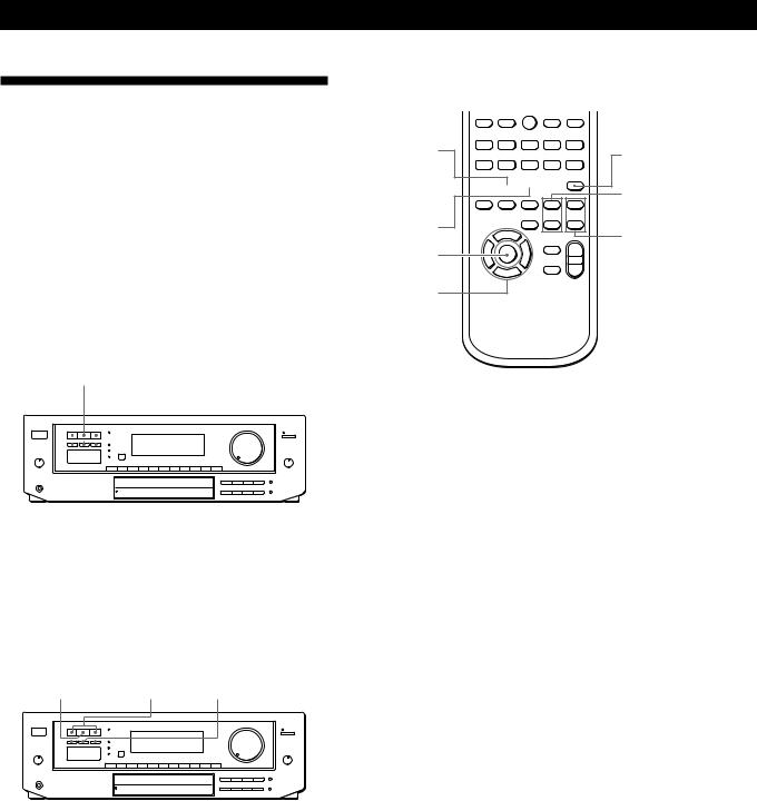
Customizing Sound Fields
You can customize the sound fields by adjusting the tone (bass or treble) and surround sound parameters while listening to a program source. The adjusted parameters are stored in memory automatically and you can use your custom sound fields just as you would use the pre-programmed ones. Before you start, select the sound field you want to customize and start playing a program.
TONE ON/OFF DPC MODE SUR indicator
|
|
|
|
|
|
|
|
|
|
|
|
|
|
|
|
|
|
|
|
|
|
|
|
|
|
|
|
|
|
|
|
|
|
|
|
|
|
|
|
|
|
|
|
|
|
|
|
|
|
|
|
|
|
|
|
|
|
|
|
|
|
|
|
|
|
|
|
|
|
|
|
|
|
|
|
|
|
|
|
|
|
|
|
|
|
|
|
|
|
|
|
|
|
|
|
|
|
|
|
|
|
|
|
|
|
|
|
|
|
|
|
|
|
|
|
|
|
|
|
|
|
|
|
|
|
|
|
|
|
|
|
|
|
|
|
|
|
|
|
|
|
|
|
|
|
|
|
|
|
|
|
|
|
|
|
|
|
|
|
Digital processing |
TONE indicator |
|
|
||||||||||||
|
control buttons |
|
|
|
|
|
|
||||||||
Adjusting the tone parameter
Adjust the tone (bass or treble) of the front, center and rear speakers for optimum sound. You can adjust the tone of all sounds fields, including Dolby Surround.
1Press TONE ON/OFF so that TONE ON appears in the display.
2Press DPC MODE repeatedly until the TONE indicator lights up.
3Use the digital processing control buttons ( /
/
 ) to select BASS or TREBLE.
4Use the digital processing control buttons ( /
/ ) to adjust the tone level.
The adjusted tone level is stored automatically.

 You can turn off the tone adjustments without erasing them
The tone adjustments and on/off setting are stored in each sound field. Press TONE ON/OFF to turn the tone parameter off or on.
Adjusting surround sound parameters
Change the surround parameters to fit your listening situation. Refer to the chart on the previous page for parameters you can adjust in each sound field.
To adjust the parameters of the DOLBY SUR sound field, see “Getting the Most Out of Dolby Pro Logic Surround Sound” on page 18.
1Press DPC MODE repeatedly until the SUR indicator lights up.
2Use the digital processing control buttons ( /
/
 ) to select the parameter you want.
3Use the digital processing control buttons ( /
/ ) to adjust the level of the parameter.
The adjusted parameters are stored automatically.
Note
If you make new adjustments to a sound field, the previous settings are replaced by the new ones.
Resetting customized sound fields to the factory settings
1If the power is on, press POWER to turn off the power.
2Hold down SOUND FIELD ON/OFF and press POWER.
“SURR CLEAR!” appears in the display and all the sound fields are reset at once.
17EN
Using Surround Sound
Getting the Most Out of Dolby
Pro Logic Surround Sound
To obtain the best possible Dolby Pro Logic Surround sound, first select the center mode according to your speaker system. Then, adjust the sound parameters of the PRO LOGIC sound field.
Note that you must have at least one additional pair of speakers and/or one center speaker to do the following adjustments.
STR-DE705/STR-DE605/STR-D650Z
SOUND FIELD
ON/OFF
GENRE |
MODE CENTER MODE |
|
|
|
|
|
|
|
|
|
|
|
|
|
|
|
|
|
|
|
|
|
|
|
|
|
|
|
|
|
|
|
|
|
|
|
|
|
|
|
|
|
|
|
|
|
|
|
|
|
|
|
|
|
|
|
|
|
|
|
|
|
|
|
|
|
|
|
|
|
|
|
|
|
|
|
|
|
|
|
|
|
|
|
|
|
|
|
|
|
|
|
|
|
|
|
|
|
|
|
|
|
|
|
|
|
|
|
|
|
|
|
|
|
|
|
|
|
|
|
|
|
|
|
|
|
|
|
|
|
|
|
|
|
|
|
|
|
|
|
|
|
|
|
|
|
|
|
|
|
|
|
|
|
|
|
|
|
|
|
|
|
|
|
|
|
|
|
|
|
|
|
|
|
|
|
|
|
|
|
|
|
|
|
|
|
|
|
|
|
|
|
|
|
|
|
|
|
|
|
|
|
|
|
|
|
|
|
|
|
|
|
|
|
|
|
|
|
TONE |
|
|
DPC |
SUR indicator |
|
|
|
|||||||||||||||
ON/OFF |
|
MODE |
|
|
|
|
|
|
|
|
|||||||||||||
|
|
|
|
|
|
|
|
|
|
|
|
|
|
|
|
|
|
|
|
|
|
|
|
Digital processing control buttons
STR-D550Z
SOUND FIELD |
SOUND FIELD |
|
ON/OFF |
</> |
CENTER MODE |
|
|
|
|
|
|
|
|
|
|
|
|
|
|
|
|
|
|
|
|
|
|
|
|
|
|
|
|
|
|
|
|
|
|
|
|
|
|
|
|
|
|
|
|
|
|
|
|
|
|
|
|
|
|
|
|
|
|
|
|
|
|
|
|
|
|
|
|
|
|
|
|
|
|
|
|
|
|
|
|
|
|
|
|
|
|
|
|
|
|
|
|
|
|
|
|
|
|
|
|
|
|
|
|
|
|
|
|
|
|
|
|
|
|
|
|
|
|
|
|
|
|
|
|
|
|
|
|
|
|
|
|
|
|
|
|
|
|
|
|
|
|
|
|
|
|
|
|
|
|
|
|
|
|
|
|
|
|
|
|
|
|
|
|
|
|
|
|
|
|
TONE |
|
|
DPC |
SUR indicator |
|
|
|
|
|||||||||||||
ON/OFF |
|
MODE |
|
|
|
|
|
|
|
|
|
||||||||||||
|
|
|
|
|
|
|
|
|
|
|
|
|
|
|
|
|
|
|
|
|
|
|
|
Digital processing control buttons
Remote (RM-P362/RM-U262)
|
|
|
|
0 |
) |
= |
+ |
GENRE |
|
|
TEST TONE |
|
|
|
|
9 |
( |
p |
P r |
SOUND FIELD 


ON/OFF
REAR
LEVEL (+/–)
MODE |
CENTER |
|
|
DPC MODE |
LEVEL (+/–) |
|
DIGITAL
PROCESSING
CONTROL
Selecting the center mode
The receiver offers you four center modes: PHANTOM, 3 CHANNEL LOGIC, NORMAL, and WIDE. Each mode is designed for a different speaker configuration. Select the mode that best suits your speaker system configuration.
1Press SOUND FIELD ON/OFF to turn on the sound fields.
2Press GENRE to select the PRO LOGIC sound field.
For STR-D550Z
Press SOUND FIELD < or > repeatedly to select the DOLBY SUR sound field and go to step 3.
3Press CENTER MODE repeatedly until the center mode you want appears in the display. Select the center mode by referring to the following chart.
18EN
 Loading...