


 Loading...
3-866-761-12(1)
Micro Satellite
System
Operating Instructions |
GB |
Mode d’emploi |
FR |
Owner’s Record
The model and serial numbers are located on the rear of the unit. Record the serial number in the space provided below. Refer to them whenever you call upon your Sony dealer regarding this product.
Model No. SA-VE505/VE502/VE305/VE302 |
Serial No. |
SA-VE505
SA-VE502
SA-VE305
SA-VE302
©1999 by Sony Corporation
WARNING
To prevent fire or shock hazard, do not expose the unit to rain or moisture.
To avoid electrical shock, do not open the cabinet. Refer servicing to qualified personnel only.
Do not install the appliance in a confined space, such as a bookcase or built-in cabinet.
NOTICE FOR THE CUSTOMERS IN THE USA
This symbol is intended to alert the user to the presence of uninsulated “dangerous voltage” within the product’s enclosure that may be of sufficient magnitude to constitute a risk of electric shock to persons.
This symbol is intended to alert the user to the presence of important operating and maintenance (servicing) instructions in the literature accompanying the appliance.
CAUTION
You are cautioned that any changes or modification not expressly approved in this manual could void your authority to operate this equipment.
Note to CATV system installer:
This reminder is provided to call CATV system installer’s attention to Article 820-40 of the NEC that provides guidelines for proper grounding and, in particular, specifies that the cable ground shall be connected to the grounding system of the building, as close to the point of cable entry as practical.
NOTICE FOR THE CUSTOMERS IN CANADA
CAUTION
TO PREVENT ELECTRIC SHOCK, DO NOT USE THIS POLARIZED AC PLUG WITH AN EXTENSION CORD, RECEPTACLE OR OTHER OUTLET UNLESS THE BLADES CAN BE FULLY INSERTED TO PREVENT BLADE EXPOSURE.
2

Table of Contents |
|
Hooking up the system ......................... |
4 |
Positioning the speakers ........................ |
7 |
Listening to the sound ........................... |
8 |
Adjusting the sound .............................. |
9 |
Precautions ............................................ |
11 |
Troubleshooting ................................... |
12 |
Specifications ........................................ |
12 |
About this manual
GB
The instructions in this manual are for SA-VE505, SA-VE502, SA-VE305, and SA-VE302, Sony Micro Satellite Systems.
Differences between the systems
•SA-VE505 and SA-VE305
The SA-VE505 and SA-VE305 are 5.1 channel speaker systems consisting of two front speakers, two rear speakers, one center speaker, and one subwoofer. Both support Sony Digital
Cinema Sound, Dolby* Pro Logic, and Dolby Digital (AC-3), and are thus geared towards the enjoyment of movies.
•SA-VE502 and SA-VE302
Consisting of two front speakers and one subwoofer, the SA-VE502 and SA-VE302 are suited for the enjoyment of music.
*Manufactured under license from Dolby Laboratories Licensing Corporation. DOLBY, the double-D symbol ;, “PRO LOGIC” and “Dolby Digital (AC-3)” are trademarks of Dolby Laboratories Licensing Corporation.
Any difference in operation is clearly indicated in the text, for example, “SA-VE505 only.”
3

Hooking up the system
Connect the speaker system to the speaker output terminals of an amplifier.
Make sure power to all components (included the subwoofer) is turned off before starting the hook-up.
Hookup A (for SA-VE505/VE305)
This configuration is used when the amplifier is connected to a DVD player, LD player, VCR or other video devices.
Subwoofer |
Center* |
|
Front (Right) |
Ee |
Front (Left) |
|
|
|
Ee LINE IN |
|
Ee |
Amplifier
FRONT
E
 e R
e R  L eEEe
WOOFER OUT CENTER R |
L |
REAR
|
Ee |
|
|
Ee |
|
|
|
|
|
|
|
Rear (Right) |
Rear (Left) |
||||
4

Hookup B (for SA-VE505/VE305)
Try this configuration instead of “Hookup A” in the following situations:
—When there are no jacks on the amplifier for a subwoofer.
—When you want stronger bass sound from the subwoofer.
Front (Right) Center* Front (Left)
Ee |
|
Ee |
|
Ee |
|
|
|
||
|
|
|
Subwoofer |
|
|
|
|
L |
L |
|
|
|
|
e |
|
|
|
|
E |
|
|
|
|
E |
|
|
|
|
e |
Amplifier |
|
|
R |
R |
|
FRONT |
|
|
|
|
|
SPEAKER |
SPEAKER |
|
E e R |
|
|
||
L |
|
IN |
OUT |
|
|
eEEe |
|
|
|
CENTER R |
L |
|
|
|
|
|
REAR |
|
|
|
Ee |
|
|
Ee |
|
|
|
|
|
|
|
Rear (Right) |
Rear (Left) |
||||
*(SA-VE505 only) Connect the center speaker to the amplifier and mount it onto the supplied speaker stand for placement on the top of the TV set (see page 7).
Terminal (jack) connections |
|
|
e |
E e |
|
e |
|
|
E |
e |
|
E |
||
|
E
continued 5

Hooking up the system (continued)
Hookup C (for SA-VE502/VE302)
This configuration is used when the amplifier is connected to a CD player, MD deck, cassette deck, or other audio devices.
Front (Right) |
|
|
|
Front (Left) |
Ee |
|
|
|
Ee |
|
|
|
Subwoofer |
|
|
|
|
L |
L |
|
|
|
|
e |
|
|
|
|
E |
Amplifier |
|
|
|
E |
FRONT |
|
|
e |
|
|
|
R |
R |
|
|
|
|
||
|
R |
|
L |
|
|
|
eEEe |
SPEAKER |
SPEAKER |
|
|
|
IN |
OUT |
Terminal connections |
|
|
|
|
e |
|
E e |
|
|
e |
|
|
|
|
E |
|
|
e |
|
E |
|
|
|
|
|
|
|
|
|
|
|
|
E |
|
Notes
•Make sure the plus (+) and the minus (–) terminals on the speakers are matched to the corresponding the plus
(+) and the minus (–) terminals on the amplifier.
•Be sure to tighten the screws of the speaker terminals securely since loose screws may become a source of noise.
•Make sure all connections are firm. Contact between bear speaker wires at the speaker terminals may cause a short-circuit.
•Do not connect the subwoofer to the amplifier’s CENTER output terminal (which is for Dolby Pro Logic or Dolby Digital (AC-3)). No bass will output from the subwoofer if you do.
•For details regarding the connections on the amplifier side, refer to the manual that was provided with your amplifier.
Tip
It is convenient to remember that all striped wires are minus (–) in polarity and should be connected to the minus (–) speaker terminals.
6
Positioning the speakers
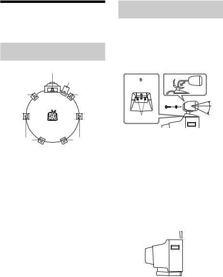
Location of each
speaker
Center* |
|
|
Subwoofer |
Front |
Front |
(Left) |
(Right) |
A |
A |
Rear* |
Rear* |
(Left) B |
B (Right) |
*SA-VE505/VE305 only |
|
Each speaker should face the listening position. Better surround effect will result if all speakers are set at the same distance from the listening position.
Place the front speakers at a suitable distance to the left and right of the television.
Place the subwoofer on either side of the television.
Place the center speaker on the top-center of the TV set.
The placement of rear speakers greatly depends on the configuration of the room. The rear speakers may be placed on both sides of the listening position A or behind the listening position B.
Tips
•Movies are best enjoyed in a room that produces no echoes (as in one with surrounding curtains).
•Music (especially classical music) is best enjoyed in a room that produces some echo.
Setting the center
speaker
SA-VE505
Attach the center speaker to supplied speaker stand and place it on a top of the TV set.
For optimum listening enjoyment, the speaker should face directly towards the listener. Adjust the angle of the speaker for that purpose.
1
3 |
2 |
3 |
|
15º |
|
|
|
25º |
Screws
Bottom view
1Pass the speaker cord into the hole on the back of the base and out from the hole at the bottom of the mount.
2Secure the center speaker to the mount with the supplied screw.
3Adjust the angle of the speaker stand. Loosen the two screws under the base to adjust the angle, then tighten them again afterwards.
SA-VE305
Attach the supplied foot pads to the bottom of the center speaker, one in each of the four corners. Set the speaker firmly on top of the TV set, then make sure it is completely level.
 Foot pads
continued 7
Positioning the speakers (continued)
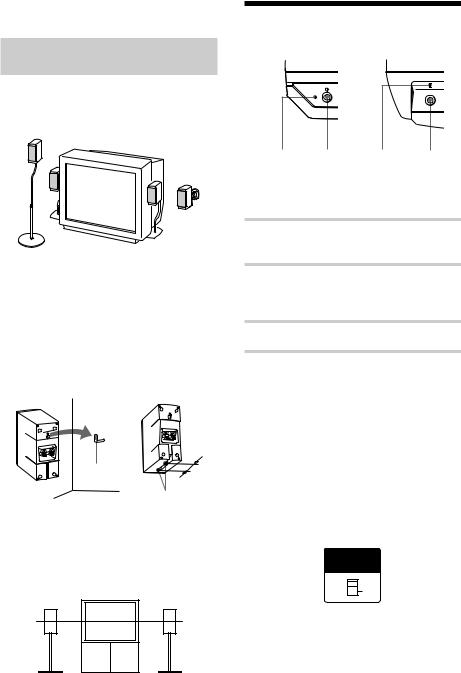
Setting up other
speakers
For greater flexibility in the positioning of the speakers, use the optional WS-FV10, WS-TV10, or WS-WV10 speaker stand (available only in certain countries).
WS-FV10 |
WS-TV10 |
WS-WV10 |
|
|
(for rear |
|
|
speakers) |
SA-VE505/VE502 only
You can attach the supplied foot pads to the bottom of the speakers, one in each corner.
SA-VE305/VE302 only
You can hang or install the front (and rear) speakers on a wall using hooks or nuts (commercially available).
Hook
60 mm
Nuts (M5)
Note
You are responsible for the proper selection and use of mounting hardware that you purchase at a hardware store, and for the proper and safe mounting of the speakers.
Tip (for SA-VE505/VE305)
The height of the front speakers should be adjusted to about the center of the TV screen.
Listening to the sound
SA-VE505/VE502 SA-VE305/VE302
ON/STANDBY
POWER
U
! indicator ! ! indicator !
First, turn down the volume on the amplifier. The volume should be set to minimum before you begin playing the program source.
1 Turn on the amplifier and select the program source.
2 Press ! on the subwoofer.
The ! indicator on the subwoofer lights up green.
3 Play the program source.
Power turns on and off automatically (SA-VE505/VE502 only)
When the subwoofer is on (i.e, the
!indicator lights up green) and there is no signal input for a few minutes, the
!indicator changes to red and the subwoofer enters power saving mode. While in this mode a signal is input to the subwoofer, the subwoofer automatically turns on (auto power on/off function).
To turn this feature off, slide the POWER SAVE switch on the rear panel to OFF.
POWER
SAVE
 AUTO
AUTO
OFF
Note
If you turn down the volume level of the subwoofer too low, the auto power on/off function may activate, causing the subwoofer to enter power saving mode.
8

Adjusting the sound
Slight adjustments to the system can enhance your sound enjoyment.
Adjusting the
subwoofer
SA-VE505/VE502
ON/STANDBY |
LEVEL |
MODE |
|
|
MOVIE |
MUSIC
MIN MAX
LEVEL MODE
1 Set MODE according to the program source as follows:
|
Source |
MODE |
|
DVD, LD, video cassette |
MOVIE |
|
or other video source |
|
|
|
|
|
MD, CD, cassette tape |
MUSIC |
|
or other audio source |
|
|
|
|
|
|
|
2 Rotate LEVEL to adjust the volume.
Set the volume level to suit the program source.
Notes
•Some amplifier functions for enhancing the sound may cause distortion in the subwoofer. If such distortion occurs, turn off those functions.
•To enjoy high-quality sound, do not turn the subwoofer volume too high.
•To increase the bass sound from the subwoofer, connect the system using “Hookup B” (see page 5).
SA-VE305/VE302
POWER |
LEVEL |
CUT OFF FREQ |
PHASE |
||
U |
MIN |
MAX |
50Hz |
200Hz |
øNORMAL |
|
|
|
|
ØREVERSE |
|
LEVEL CUT OFF FREQ PHASE
1 Rotate CUT OFF FREQ to set a cut-off frequency of 100 Hz to 150 Hz (or between 1 o’clock and 3 o’clock position, in terms of position).
For Dolby Digital (AC-3), set the cut-off frequency to the maximum level
(200 Hz).
2 Rotate LEVEL to adjust the volume.
Set the volume level to suit the program source.
3 Press PHASE to select the phase polarity (NORMAL or REVERSE).
Set PHASE to NORMAL when Dolby Digital (AC-3) is on.
Tip
The proper phase polarity depends on the location of a subwoofer or adjustment of the cut-off frequency.
Try both settings and select the one that suits your listening taste.
Notes
•Some amplifier functions for enhancing the sound may cause distortion in the subwoofer. If such distortion occurs, turn off those functions.
•To enjoy high-quality sound, do not turn the subwoofer volume too high.
•To increase the bass sound from the subwoofer, connect the system using “Hookup B” (see page 5).
continued 9
Loading...