


SAC-5-B
Table of contents
 Loading...
SA-C5B
AEP Model
UK Model
E Model
Australian Model
Chinese Model
SERVICE MANUAL
SPEAKER SYSTEM
Sony Corporation
Home Audio Company
Published by Sony Engineering Corporation
9-873-219-03
2002A1600-1
© 2002.1
• SA-C5B is the speaker system
in CMT-C5.
SPECIFICATIONS
Ver 1.2 2002. 01
Speaker system Two-way, bass reflex
system
Speaker units 9 cm dia., cone type
woofer
2.5 cm dia., balance drive
tweeter
Rated impedance 6 ohms
Dimensions (w/h/d) Approx. 149 × 248 ×
220 mm
Mass Approx. 1.9 kg net per
speaker
SAFETY-RELATED COMPONENT WARNING!!
COMPONENTS IDENTIFIED BY MARK 0 OR DOTTED LINE WITH
MARK 0 ON THE SCHEMATIC DIAGRAMS AND IN THE PARTS
LIST ARE CRITICAL TO SAFE OPERATION. REPLACE THESE
COMPONENTS WITH SONY PARTS WHOSE PART NUMBERS
APPEAR AS SHOWN IN THIS MANUAL OR IN SUPPLEMENTS
PUBLISHED BY SONY.
2
SA-C5B
SERVICE NOTE
[When bringing in the equipment for service]
The notice is shown on both Warranty Card and Repair Service column of operation manual, telling to bringing in both
of the equipment (HCD-C5) and speaker system (SA-C5B) together to service station when service (repair) is needed.
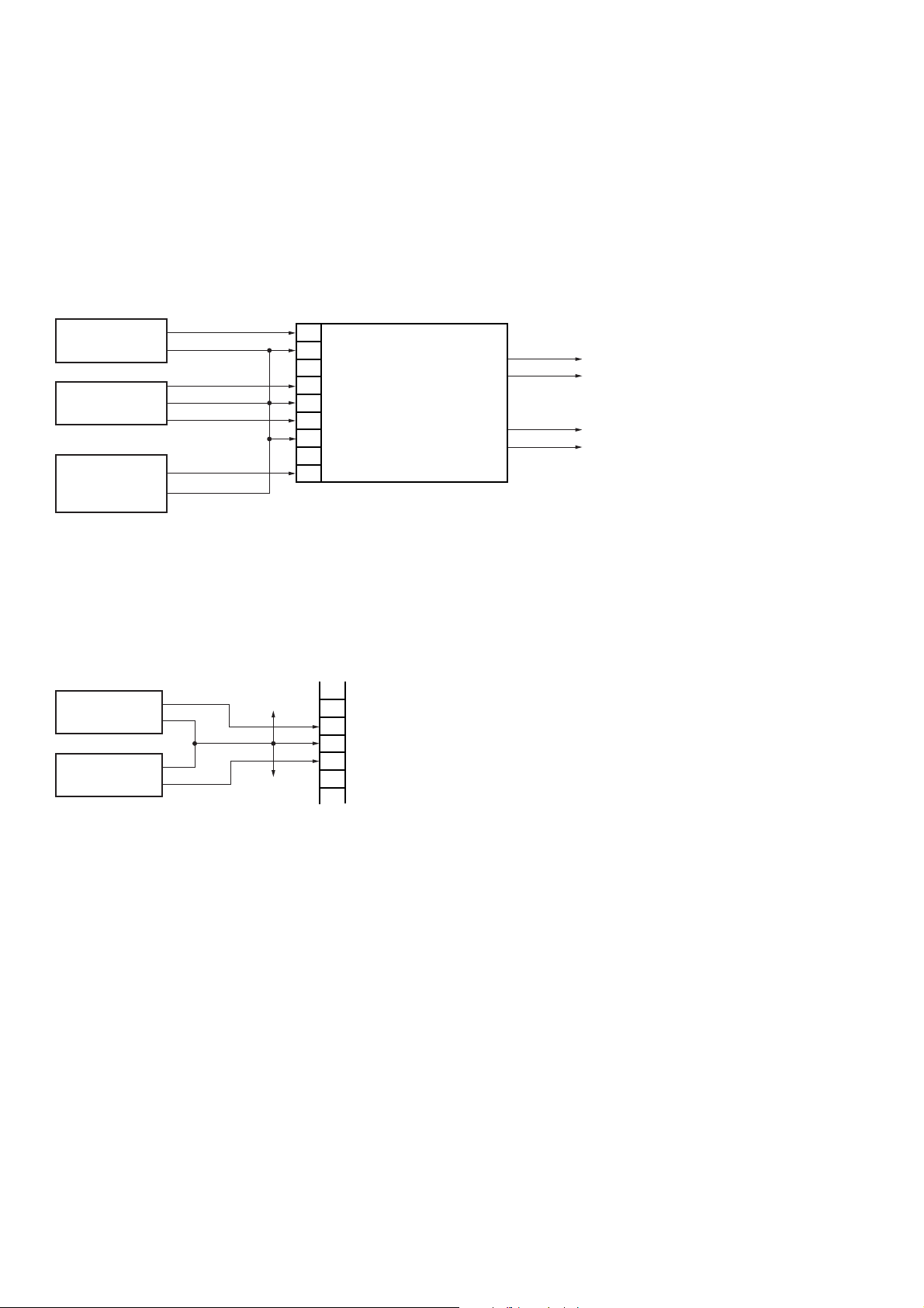
[How to check speaker only]
When only speaker is brought in for service, check its operations by supplying both the power and the signal to the AMP
board of the speaker as shown below.
Check method :
1.Perform connection as shown below.
• DC regulated power supply 1 (+5 V)
It functions to turn on the speaker relay driver.
• DC regulated power supply 2 (±20 V)
It is desirable to use the DC regulated power supply of the dual tracking type that can supply its output voltages in tw o
polarities of positive and negative polarities. However, the two units of the DC regulated pow er supply that supplies
only a single output voltage can also be used. (See the figure below.)
• Audio signal generator
Output frequency : 1 kHz
Output voltage : 100mV p-p or less
Output impedance : 600 Ω
2.Turn on the main power of the DC regulated power supply 2.
Then turn on the main power of the DC regulated power supply 1 (+ 5 V).
After that, input the output signal of the audio signal generator as shown.
3.Check that the LED (D831, D832 (BLUE)) turns on and the audio signal can be heard from the speaker.
Notes :
1 For the speaker cord, disconnect it from the speaker or leave it open.
2 Be careful not to apply an excessive input audio signal to the speaker.
3 If the power voltage is less than +/- 14 V, the speaker relay will not be activated.
[Caution when removing the front panel]
The special screwdriver (Sony part code No. 7-640-005-55) of star type (six star type) is required to remove the front
panel.
9
8
7
6
5
4
3
2
1
DC regulated
power supply 2
Audio signal
generator
RELAY
SP-GND
+B
POWER-GND
-B
SHIELD GND
PRE-SIGNAL
CN801 AMP board
LED (BLUE)
Speaker
DC regulated
power supply 1
+5V
GND
GND
+
+
+20V
-20V
AUDIO SIGNAL
COM
-
-
DC regulated
power supply
+
-
DC regulated
power supply
+
-
7
6
5
4
3
+B
POWER-GND
-B
CN801
+20V
-20V
Ver 1.1 2001.09
33
SA-C5B
• Semiconductor
Location
(AMP BOARD)
IC801
1
2
4
5
91
12
12
D831, D832
– BACK LIGHT FOR SP2 –
• Semiconductor
Location
(LED BOARD)
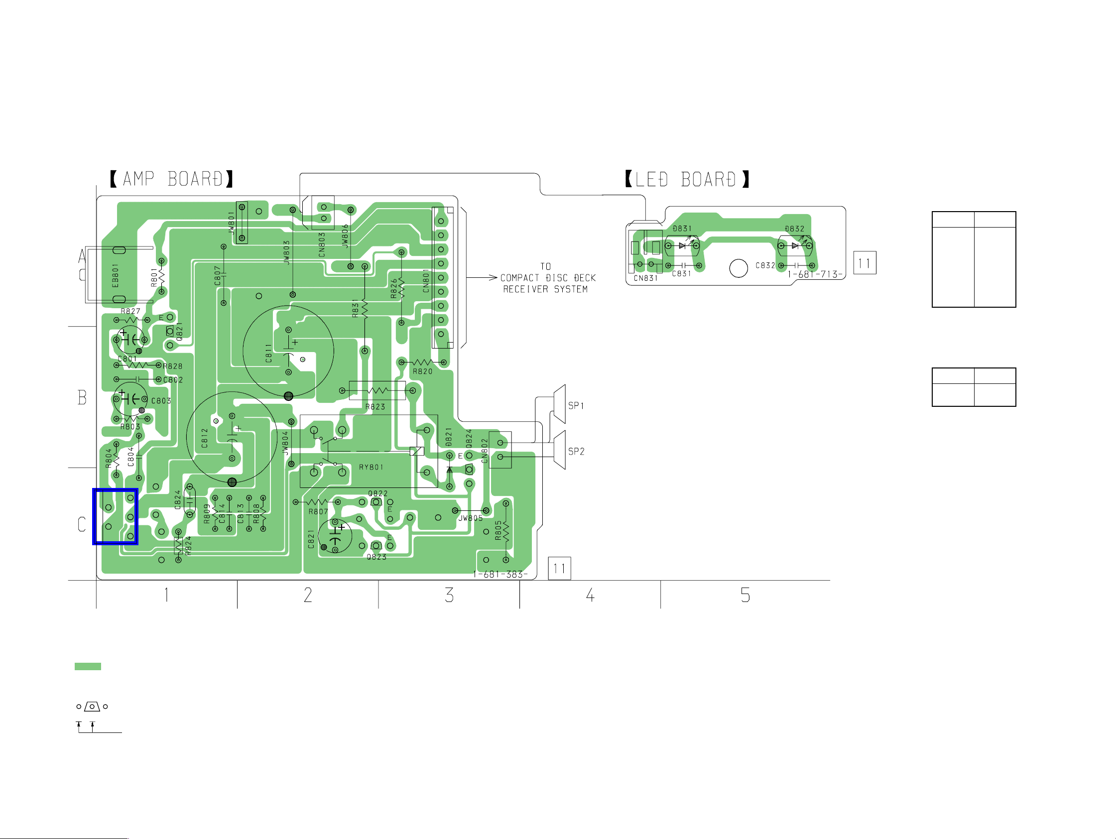
1-1. PRINTED WIRING BOARD
Ref. No. Location
D831 A-5
D832 A-5
Ref. No. Location
D821 B-3
IC801 C-1
Q821 B-1
Q822 C-2
Q823 C-2
Q824 C-3
SECTION 1
DIAGRAMS
Note on Printed Wiring Board:
• X : parts extracted from the component side.
• : Pattern from the side which enables seeing.
• Indication of transistor
B
These are omitted.
CE
Q
Loading...