


4-086-475-22 (1)
Trinitron®
Color Video Monitor
Operating Instructions |
|
|
US |
|||||||||||||||
|
|
|
|
|
|
|
|
|
|
|
|
|
|
|
|
|
|
|
Mode d’emploi |
|
|
FR |
|||||||||||||||
|
|
|
||||||||||||||||
|
|
|
|
|
|
|||||||||||||
Manual de instrucciones |
|
ES |
||||||||||||||||
|
|
|
|
|
|
|
|
|
|
|
|
|
|
|
|
|
|
|
|
|
|
|
|
|
|
|
|
|
|
|
|
|
|
|
|
|
|
|
|
|
|
|
|
|
|
|
|
|
|
|
|
|
|
|
|
|
|
|
|
|
|
|
|
|
|
|
|
|
|
|
|
|
|
|
|
|
|
|
|
|
|
|
|
|
|
|
|
|
|
|
|
|
|
|
|
|
|
|
|
|
|
|
|
|
|
|
|
|
|
|
|
|
|
PVM-14L5
PVM-20L5
2001 Sony Corporation

English
Owner’s Record
The model and serial numbers are located at the rear. Record these numbers in the spaces provided below. Refer to these numbers whenever you call upon your Sony dealer regarding this product.
Model No.
Serial No.
WARNING
To prevent fire or shock hazard, do not expose the unit to rain or moisture.
Dangerously high voltage are present inside the unit.
Do not open the cabinet. Refer servicing to qualified personnel only.
In the event of a malfunction or when maintenance is necessary, consult an authorized Sony dealer.
For the customers in the U.S.A.
This equipment has been tested and found to comply with the limits for a Class A digital device, pursuant to Part 15 of the FCC Rules. These limits are designed to provide reasonable protection against harmful interference when the equipment is operated in a commercial environment.
This equipment generates, uses, and can radiate radio frequency energy and, if not installed and used in accordance with the instruction manual, may cause harmful interference to radio communications. Operation of this equipment in a residential area is likely to cause harmful interference in which case the user will be required to correct the interference at his own expense.
You are cautioned that any changes or modifications not expressly approved in this manual could void your authority to operate this equipment.
For the customers in Canada
This Class A digital apparatus complies with Canadian ICES-003.
Pour les utilisateurs au Canada
Cet appareil numérique de la classe A est conforme à la norme NMB-003 du Canada.
ATTENTION – When the product is installed in a rack:
a)Elevated operating ambient temperature
If installed in a closed or multi-unit rack assembly, the operating ambient temperature of the rack environment may be greater than room ambient. Therefore, consideration should be given to installing the equipment in an environment compatible with the manufacture’s maximum rated ambient temperature (Tmra: 0°C to 35°C (32°F to 95°F)).
b)Reduced air flow
Installation of the equipment in a rack should be such that the amount of air flow required for safe operation of the equipment is not compromised.
c)Mechanical loading
Mounting of the equipment in the rack should be such that a hazardous condition is not achieved due to uneven mechanical loading.
d)Circuit overloading
Consideration should be given to the connection of the equipment to the supply circuit and the effect that overloading of circuits might have on overcurrent protection and supply wiring. Appropriate consideration of equipment nameplate ratings should be used when addressing this concern.
e)Reliable earthing
Reliable earthing of rack-mounted equipment should be maintained. Particular attention should be given to supply connections other than direct connections to the branch circuit (e.g., use of power strips).
f)Gap keeping
Upper and lower gap of rack-mounted equipment should be kept 44 mm (1 3/4 inches).
2 (US)

Precaution
On safety
•Operate the unit only with a power source as specified in “Specifications” section.
•The nameplate indicating operating voltage, power consumption, etc., is located at the rear.
•Should any solid object or liquid fall into the cabinet, unplug the unit and have it checked by qualified personnel before operating it any further.
•Do not drop or place heavy objects on the power cord. If the power cord is damaged, turn off the power immediately. It is dangerous to use the unit with a damaged power cord.
•Unplug the unit from the wall outlet if it is not to be used for several days or more.
•Disconnect the power cord from the AC outlet by grasping the plug, not by pulling the cord.
•The socket-outlet shall be installed near the equipment and shall be easily accessible.
On installation
•Allow adequate air circulation to prevent internal heat build-up.
Do not place the unit on surfaces (rugs, blankets, etc.) or near materials (curtains, draperies) that may block the ventilation holes.
•Do not install the unit in a location near heat sources such as radiators or air ducts, or in a place subject to direct sunlight, excessive dust, mechanical vibration or shock.
On cleaning of the CRT surface
•The surface of the CRT has an optional PET film treatment.
Clean the CRT surface using the following method to avoid damaging the surface.
•Clean the CRT with a soft cloth.
When the CRT is dirtied with oily hands or fingerprints, clean it with a soft cloth moistened with a mild detergent solution.
•Never use abrasive cleansers, alkaline soap, strong solvents such as alcohol, thinner or benzine, since they will damage the surface.
•Do not rub the surface of the CRT with a solid object or hit it.
On cleaning
To keep the unit looking brand-new, periodically clean it with a mild detergent solution. Never use strong solvents such as thinner or benzine, or abrasive cleansers since they will damage the cabinet. As a safety precaution, unplug the unit before cleaning it.
On repacking
Do not throw away the carton and packing materials. They make an ideal container which to transport the unit. When shipping the unit to another location, repack it as illustrated on the carton.
If you have any questions about this unit, contact your authorized Sony dealer.
US
English
3 (US)

Table of contents
|
|
|
..................................................................Precaution |
3 |
(US) |
Features ...................................................................... |
5 |
(US) |
Connections ............................................................... |
7 |
(US) |
How to Connect the AC Power Cord ............................. |
7 (US) |
|
How to Connect a Cable to a BNC Connector ............... |
7 (US) |
|
Location and Function of Parts and Controls ........ |
8 |
(US) |
Control Panels ................................................................ |
8 (US) |
|
Rear Panel .................................................................... |
10 (US) |
|
Selecting the Menu Language ................................ |
13 |
(US) |
Using the Menu ........................................................ |
14 |
(US) |
Display List .............................................................. |
15 |
(US) |
STATUS Menu .......................................................... |
17 |
(US) |
COLOR TEMP/BAL Menu ........................................ |
17 |
(US) |
USER CONTROL 1/2, 2/2 Menu .............................. |
18 |
(US) |
USER CONFIG 1/2, 2/2 Menu .................................. |
19 |
(US) |
REMOTE 1/2 PARALLEL Menu ............................... |
20 |
(US) |
REMOTE 2/2 SERIAL Menu ..................................... |
20 |
(US) |
OPTION CONFIG Menu ........................................... |
21 |
(US) |
KEY PROTECT Menu ............................................... |
22 |
(US) |
Troubleshooting ...................................................... |
22 |
(US) |
Specifications .......................................................... |
23 |
(US) |
The explanation given in this manual can be applied to the following models unless noted otherwise.
When explanation differs among models, this is clearly indicated in this manual.
•PVM-14L5 (14-inch monitor)
•PVM-20L5 (20-inch monitor)
Illustrations of the video monitor are of the PVM-14L5.
4 (US)

Features
The PVM-14L5/PVM-20L5 is a Trinitron color video monitor for professional use.
Picture
HR (High Resolution) Trinitron1) picture tube for PVM-14L5 and PVM-20L5
HR Trinitron tube provides a high resolution picture. Horizontal resolution is more than 800 TV lines at the center of the picture.
Comb filter
When NTSC video signals are received, a comb filter activates to make more accurate Y/C separation. This contributes to less of a decrease in resolution, cross color and cross luminance phenomena.
Beam current feedback circuit
The built-in beam current feedback circuit assures stable white balance.
Two color system available
The monitor can display NTSC and PAL signals. The appropriate color system is selected automatically.
Auto chroma phase function
The chroma and phase of the decoder are automatically adjusted with the auto chroma phase function.
Blue only mode
In the blue only mode, an apparent monochrome display is obtained with all three of the R/G/B cathodes driven with a blue signal. This facilitates color saturation and phase adjustments and observation of VCR noise.
Input
Analog RGB/component input connectors
Analog RGB or component (Y, R-Y and B-Y) signals from video equipment can be input through these connectors. Select either of two signals using the RGB/ COMP input switch button.
Y/C input connectors (S-input connector)
The video signal, split into the luminance signal (Y) and the chrominance signal (C), can be input through this connector, eliminating the interference between the two signals, which tends to occur in a composite video signal, ensuring video quality.
Expandable input capability
You can easily expand the input capability by installing an input adaptor (not supplied) in the input option slot in the rear of the monitor.
External sync input
When the EXT SYNC selector is in the on position, the monitor can be operated on the sync signal supplied from an external sync generator.
Automatic termination (connector with  mark only)
The input connector is terminated at 75 ohms inside when nothing has been connected to the output connector. If a cable is connected to the output connector, the internal terminal is automatically released and the signals input to the input connector are output to the output connector (loop-through).
Functions
Multiformat
The monitor supports the principal formats (480I/ 480P/720P/1080I) for digital broadcasts as well as conventional NTSC and PAL color systems — a wide variety of signals whose horizontal frequency is between 15 kHz and 45 kHz.
Underscan mode
The signal normally scanned outside of the screen can be monitored in the underscan mode.
Note
When the monitor is in the underscan mode, the dark RGB scanning lines may appear on the top edge of the screen. These are caused by an internal test signal, rather than the input signal.
Horizontal/vertical delay mode
The horizontal and vertical sync signals can be monitored simultaneously in the H/V delay mode.
.........................................................................................................................................................................................................
1) “Trinitron” is a registered trademark of Sony Corporation.
5 (US)

Features
Internal Caption Vision (Closed Caption) Decoder
When the image signals with caption vision signals are input, the English subtitles are superimposed and displayed on the screen. You can select the caption ON/OFF and the caption type in the menu.
Auto/manual degaussing
The CRT is automatically degaussed when the power is turned on. You can manually degauss the CRT by pressing the DEGAUSS button.
In the menu, you can set the time to automatically degauss after turning on the power.
Note
The DEGAUSS button is disabled when the screen menu is being displayed.
To manually degauss the CRT, exit the screen menu by pressing the MENU button.
On-screen menus
You can set color temperature, CHROMA set up, and other settings by using the on-screen menus.
EIA 19-inch rack mount bracket available
The monitor may be mounted on an EIA-standard 19inch rack, using an optional mounting bracket MB-521 or slide rail SLR-104 (for PVM-14L5 and PVM20L5).
For details on mounting the monitor on the rack, refer to the Operating Instructions of the mounting bracket or slide rail.
6 (US)
Connections
How to Connect the AC Power
Cord
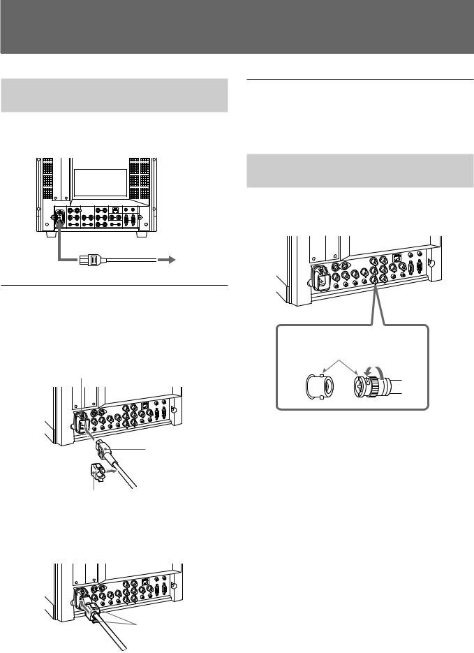
Connect the AC power cord (supplied) to the AC IN socket on the rear panel and to a wall outlet.
to AC IN
to a wall outlet
To connect an AC power cord securely with AC plug holder
1 Plug the power cord into the AC IN socket. Then, attach the AC plug holder (supplied) on top of the AC power cord.
AC IN socket
AC power plug
AC plug holder
2 Slide the AC plug holder over the cord until it locks.
Lock levers
To remove the AC power cord
Pull out the AC plug holder while pressing the lock levers.
How to Connect a Cable to a
BNC Connector
Connect a coaxial cable with the BNC plugs to the BNC connectors on the rear panel as illustrated below.
Insert the BNC plug into the connector on the rear panel, matching the slit and pin, and turn the BNC plug clockwise to secure the connection.
7 (US)

LocationLocationand FuandctionFunctionof Parts a dofControlsParts and Controls
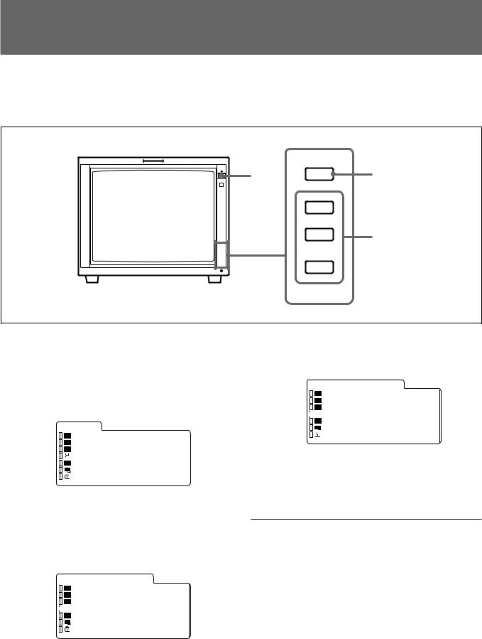
Control Panels
qd qf qg qh qj qk
ql w; wa ws wd wf wg wh
LINE
A
LINE
B
RGB/
COMP
OPTION
A
OPTION
B
EXT
SYNC
UNDER SCAN
16:9
BLUE ONLY
MONO
H/V
DELAY
4:3
MARKER
DEGAUSS
RESET
qa |
1 |
|
CONTROL
2
VOLUME 3
CONTRAST 4
qs
PHASE 5
CHROMA |
6 |
|
BRIGHT |
7 |
|
MENU |
8 |
|
UP |
9 |
|
DOWN |
||
|
||
ENTER |
0 |
1 POWER switch ( )
)
Press the switch to turn on the power. The operation buttons on both sides of the unit turn on. Press the switch again to turn off the power.
2 CONTROL button
Press this button to turn on and enables the operation button. Press this button again to turn off and disables the operation buttons.
You can adjust the brightness of the operation buttons by using the UP or DOWN buttons.
3 VOLUME control button
Press the + button to increase the volume or – button to decrease the volume.
4 CONTRAST control button
Press the + button to make the contrast higher or the – button to make it lower.
5 PHASE control button
Press the + button to make the complexion greenish or the – button to make it purplish.
6 CHROMA control button
Press the + button to increase the color intensity or the
– button to decrease it.
7 BRIGHT (brightness) control button
Press the + button to increase the brightness or the – button to decrease it.
Notes
•The PHASE (5) and CHROMA (6) control buttons have no effect on the pictures of RGB signals.
•The PHASE (5) control button has no effect on the PAL signals and pictures of component signals.
8 MENU button
Press this button to display or exit the main menu.
8 (US)

9UP button Down button
Use these buttons to select an item from a menu or adjust the values. If the menu is not displayed, you can use these buttons to adjust the brightness for the control panels. You can adjust the brightness at 5 levels.
0 ENTER button
Press the button to confirm a selected item on the menu.
qa Tally lamp
Lights up when the video camera connected to this monitor is selected, indicating that the picture is being recorded.
For details on how to light the tally lamp, see page 25 (US).
qs POWER indicator
Press the POWER switch, the indicator will light green.
qd LINE A (INPUT A) select button
Press this button to monitor the signal through the LINE A connector.
qf LINE B (INPUT B) select button
Press this button to monitor the signal through the LINE B connector.
qg RGB/COMP select button
Press this button to monitor the signal through the RGB/COMPONENT connectors.
You can set the RGB/COMPONENT in the menu screen. For details, see page 19 (US).
qh OPTION A button
This button is used if an option board has been installed in the option slot in the monitor’s rear. Press this button to monitor the image/audio signals from the option board input 1.
qj OPTION B button
This button is used if an option board has been installed in the option slot in the monitor’s rear. Press this button to monitor the image/audio signals from the option board input 2.
(This button is disabled if BKM-129X or BKM155DV is used.)
qk EXT SYNC (external sync) button
Press this button to operate the monitor on an external sync signal through the EXT SYNC IN connector.
ql UNDER SCAN button
Press this button (light on) for underscanning.
The display size is reduced by approximately 5% so that four corners of the raster are visible.
w; 16:9 button
Press this button to monitor the signals of 16:9 picture.
Note
The aspect ratio is fixed to 16:9 when the signal other than 4:3 signal format is input.
wa BLUE ONLY button
Press this button to eliminate the red and green signals. Only blue signal is displayed as an apparent monochrome picture on the screen. This facilitates “chroma” and “phase” adjustments and observation of VCR noise.
ws MONO button
Press this button to display a monochrome picture. When the buttons is pressed again, the monitor switches automatically to color mode.
wd H/V DELAY button
Press this button to observe the horizontal and vertical sync signals at the same time.
The horizontal sync signal is displayed in the left quarter of the screen; the vertical sync signal is displayed near the center of the screen.
wf 4:3 MARKER button
When this button is pressed, a 4:3 marker is displayed and it is possible to check the 4:3 aspect area.
Note
The 4:3 marker is not displayed when the signals of the 4:3 aspect ratio are monitored or the monitor is in H/V delay mode
wg DEGAUSS button
Press this button momentarily. The screen will be demagnetized. Wait for 10 minutes or more before using this button again.
wh RESET button
Pressing this button while changing the menu setting resets the menu to the previous setting. Pressing this button while changing VOLUME, PHASE, CHROMA or BRIGHT resets the respective setting to the default.
9 (US)

Location and Function of Parts and Controls
Rear Panel |
|
|
|
|
|
|
|
|
|
|
|
1 |
|
|
|
|
|
|
|
|
|
2 |
3 |
|
4 |
|
5 |
6 |
7 |
|
8 |
|
AC IN |
LINE A |
|
LINE B |
RGB/COMPONENT |
PARALLEL REMOTE |
OPTION AUDIO INPUT |
||||
|
|
|
|
|
G/Y |
|
|
|
1 |
2 |
IN |
OUT |
IN |
OUT |
IN |
OUT |
IN |
EXT |
OUT |
SERIAL REMOTE |
|
|
VIDEO |
|
VIDEO |
|
B/PB |
|
SYNC |
|
IN |
OUT |
|
|
|
|
|
|
|
|
|||
IN |
OUT |
IN |
OUT |
IN |
OUT |
IN |
AUDIO |
OUT |
|
|
|
AUDIO |
|
AUDIO |
|
R/PR |
|
|
|
|
|
|
|
|
|
|
|
|
|
|
9 |
|
1 Option slot
You can insert an option board into this option slot. To use this slot, remove the slot cover by removing the screws.
You can install only one option board. For details on how to install a board, refer to the Operating Instructions supplied with the option board.
2 AC IN socket
Connect the supplied AC power cord to this socket and to a wall outlet.
3 LINE A connectors
Line input connectors for the Y/C separate input/ output of a VCR, composite video and audio signals and their loop-through output connectors.
To monitor the input signal through these connectors, press the LINE A select button on the front panel.
If you connect the Y/C input and video input simultaneously, the Y/C input is selected first.
Y/C IN (4-pin mini-DIN)
Connect to the Y/C separate output of a VCR, video camera or other video equipment.
Y/C OUT (4-pin mini-DIN)
Loop-through output of the Y/C IN connector. Connect to the Y/C separate input of a VCR or another monitor.
When the cable is connected to this connector, the 75-ohm termination of the input is automatically released, and the signal input to the Y/C IN connector is output from this connector.
VIDEO IN (BNC)
Connect to the video output of video equipment, such as a VCR or a color video camera.
For a loop-through connection, connect to the video output of another monitor.
10 (US)
VIDEO OUT (BNC)
Loop-through output of the VIDEO IN connector. Connect to the video input of a VCR or another monitor.
When the cable is connected to this connector, the 75-ohm termination of the input is automatically released, and the signal input to the VIDEO IN connector is output from this connector.
AUDIO IN (phono jack)
Connect to the audio output of a VCR or to a microphone via a suitable microphone amplifier. For a loop-through connection, connect to the audio output of another monitor.
AUDIO OUT (phono jack)
Loop-through output of the AUDIO IN connector. Connect to the audio input of a VCR or another monitor.
4 LINE B connectors
Line input connectors for the composite video and audio signals and their loop-through output connectors. To monitor the input signal through these connectors, press the LINE B select button on the front panel.
VIDEO IN (BNC)
Connect to the video output of video equipment, such as a VCR or a color video camera.
For a loop-through connection, connect to the video output of another monitor.
VIDEO OUT (BNC)
Loop-through output of the VIDEO IN connector. Connect to the video input of a VCR or another monitor.
When the cable is connected to this connector, the 75-ohm termination of the input is automatically released, and the signal input to the VIDEO IN connector is output from this connector.
AUDIO IN (phono jack)
Connect to the audio output of a VCR or to a microphone via a suitable microphone amplifier. For a loop-through connection, connect to the audio output of another monitor.
AUDIO OUT (phono jack)
Loop-through output of the AUDIO IN connector. Connect to the audio input of a VCR or another monitor.
5 RGB/COMPONENT connectors
RGB signal or component (G/Y, B/PB, R/PR) signal input/output connectors and their loop-through output connectors.
To monitor the input signal through these connectors, press the RGB/COMP select button on the front panel.
G/Y, B/PB, R/PR IN (BNC)
When the EXT SYNC button on the front panel is not pressed (the indicator lights in green), the monitor operates on the sync signal from the G/Y signal.
To monitor the RGB signal
Connect to the analog RGB signal outputs of a video camera, etc.
To monitor the component signal
Connect to the component signal outputs of a Sony Betacam video camera, etc.
G/Y, B/PB, R/PR OUT (BNC)
Loop-through outputs of the G/Y, B/PB, R/PR IN connectors.
When the cables are connected to these connectors, the 75-ohm termination of the inputs is automatically released, and the signal inputs to G/ Y, B/PB, R/PR IN connectors are output from these connectors.
To output the RGB signal
Connect to the analog RGB signal inputs of a video printer or another monitor.
To output the component signal
Connect to the component signal inputs of a Betacam video recorder, etc.
AUDIO IN (phono jack)
Connect to the audio output of video equipment when the analog RGB or component signal is input.
AUDIO OUT (phono jack)
Loop-through output of the AUDIO IN connector.
11 (US)

Location and Function of Parts and Controls
6 EXT SYNC (external sync) connectors
Press the EXT SYNC button on the front panel (the indicator lights in amber) to use the sync signal through this connector.
IN (BNC)
When this monitor operates on an external sync signal, connect the reference signal from a sync generator to this connector.
OUT (BNC)
9SERIAL REMOTE connector (D-sub 9 pins)
SERIAL REMOTE IN
Connect this connector to the Serial Remote Control connector on the BVM series unit.
You can control the functions except the menu in the control panel of the unit from the BVM.
SERIAL REMOTE OUT
Loop-through output of the SERIAL REMOTE IN connector.
Loop-through output of the IN connector. Connect to the external sync input of video equipment to be synchronized with this monitor.
When the cable is connected to this connector, the 75-ohm termination of the input is automatically released, and the signal input to the IN connector is output from this connector.
7 PARALLEL REMOTE terminal (modular connector)
Form a parallel switch and controls the monitor externally.
For details on the pin assignment and factory setting function assigned to each pin, see page 25 (US).
8 OPTION AUDIO INPUT 1, 2 input connectors
If an option board has been installed in the option slot, input the audio into these connectors. Connect to the audio output of a VCR or to a microphone amplifier. You can connect up to 2 systems. To monitor the audio signals input from the OPTION AUDIO INPUT 1/2, press either the OPTION A or OPTION B buttons.
Note
If you use an optional board (e.g. BKM-150CP) with the audio capability, the audio input into this connector is ignored.
12 (US)
Selecting the Menu Language
You can select one of six languages (English, German, French, Italian, Spanish, Japanese) for displaying the menu and other on-screen displays.
The factory setting is ENGLISH (English).
1 MENU
UP
DOWN
2
3,4,5
ENTER
1 Press the POWER switch to turn on the monitor.
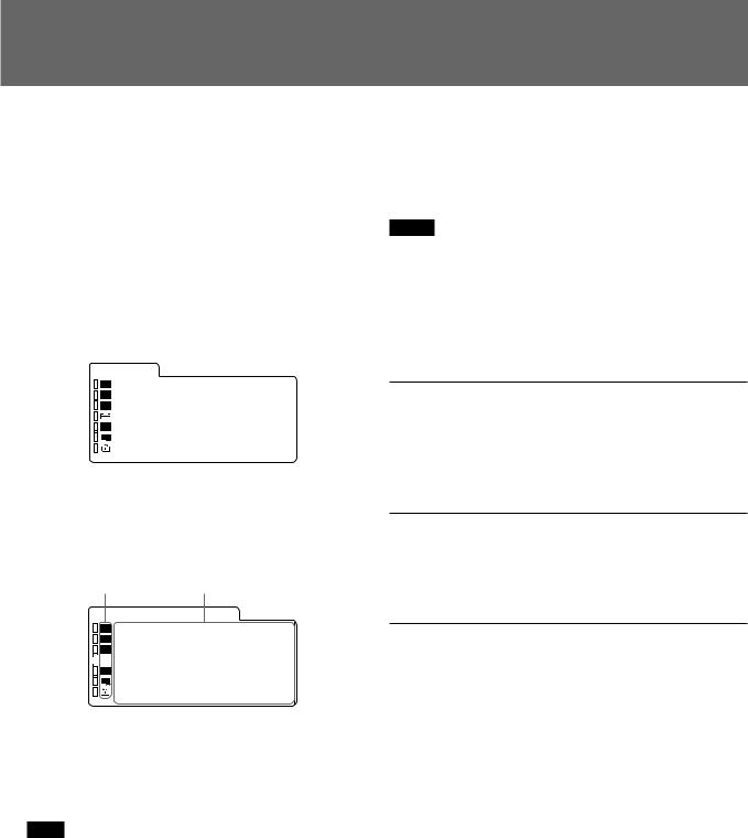
2 Press the MENU button. The menu appears.
The menu presently selected is shown as a yellow button.
S T A T U S
|
|
|
|
F O R M A T |
C O M P O N E N T |
|
|
|
|
|
|
|
1 0 8 0 / 6 0 I |
|
|
|
|
|
|
|
|
|
|
|
|
|
|
|
|
|
|
C O L O R T E M P |
|
D 9 3 |
|
|
|
|
C O M P L E V E L |
|
S M P T E |
|
|
|
|
N T S C S E T U P |
|
0 |
|
|
|
|
R G B / C O M P S E L |
C O M P |
|
|
|
|
|
|||
|
|
|
|
|||
|
|
|
|
O P T I O N |
|
|
|
|
|
|
|
|
|
3 Press the UP or DOWN button to select the USER CONFIG 1/2 (User Configuration 1/2) menu, then press the ENTER button.
The setting items (icons) in the selected menu are displayed in yellow.
U S E R C O N F I G 1 / 2
|
|
|
|
xR G B / C O M P S E L |
C O M P |
|
|
|
|
|
· 1 1 2 5 / 6 0 I S Y S |
1 0 8 0 |
|
|
|
|
|
|
||
|
|
|
|
|
||
|
|
|
|
· M A T R I X |
6 0 1 |
|
|
|
|
|
· C O M P L E VE L |
S M P T E |
|
|
|
|
|
· N T S C SE T U P |
0 |
|
|
|
|
|
· F O R M A T D I S P |
A U T O |
|
|
|
|
|
· L A N G UA G E |
E N G L I S H |
|
|
|
|
|
|
|
|
4 Press the UP or DOWN button to select “LANGUAGE,” then press the ENTER button. The selected item is displayed in yellow.
U S E R C O N F I G 1 / 2
|
|
|
|
· R G B / C O M P S E L |
C O M P |
|
|
|
|
|
· 1 1 2 5 / 6 0 I S Y S |
1 0 8 0 |
|
|
|
|
|
|
||
|
|
|
|
|
||
|
|
|
|
· M A T R I X |
6 0 1 |
|
|
|
|
|
· C O M P L E VE L |
S M P T E |
|
|
|
|
|
· N T S C SE T U P |
0 |
|
|
|
|
|
· F O R M A T D I S P |
A U T O |
|
|
|
|
|
|
||
|
|
|
|
x L A N G U A G E |
E N G L I S H |
|
|
|
|
|
|
|
|
5 Press the UP or DOWN button to select a language, then press the ENTER button. The menu changes to the selected language.
To clear the menu
Press the MENU button.
The menu disappears automatically if a button is not pressed for one minute.
13 (US)
Using the Menu
The monitor is equipped with an on-screen menu for making various adjustments and settings such as picture control, input setting, set setting change, etc. You can also change the menu language displayed in the on-screen menu.
To change the menu language, see “Selecting the Menu Language” on page 13 (US).
1 Press the MENU button. The menu appears.
The menu presently selected is shown as a yellow button.
S T A T U S
|
|
|
|
F O R M A T |
C O M P O N E N T |
|
|
|
|
|
|
|
1 0 8 0 / 6 0 I |
|
|
|
|
|
|
|
|
|
|
|
|
|
|
|
|
|
|
C O L O R T E M P |
|
D 9 3 |
|
|
|
|
C O M P L E V E L |
|
S M P T E |
|
|
|
|
N T S C S E T U P |
|
0 |
|
|
|
|
R G B / C O M P S E L |
C O M P |
|
|
|
|
|
|||
|
|
|
|
O P T I O N |
|
|
|
|
|
|
|
|
|
2 Use the UP or DOWN button to select a menu, then press the ENTER button.
The menu icon presently selected is shown in yellow and setting items are displayed.
Menu |
Setting items |
||||||
U S E R C O N F I G 1 / 2 |
|
|
|||||
|
|
|
|
xR G B / C O M P S E L |
C O M P |
|
|
|
|
|
|
· 1 1 2 5 / 6 0 I S Y S |
1 0 8 0 |
|
|
|
|
|
|
|
|||
|
|
|
|
|
|||
|
|
|
|
· M A T R I X |
6 0 1 |
|
|
|
|
|
|
· C O M P L E VE L |
S M P T E |
|
|
|
|
|
|
· N T S C |
SE T U P |
0 |
|
|
|
|
|
· F O R M A T D I S P |
A U T O |
|
|
|
|
|
|
· L A N G UA G E |
E N G L I S H |
|
|
|
|
|
|
|
|
|
|
3 Select an item.
Use the UP or DOWN button to select the item, then press the ENTER button.
The item to be changed is displayed in yellow.
Note
If the menu consists of multiple pages, press UP/ DOWN to go to the desired menu page.
4 Make the setting or adjustment on an item.
When changing the adjustment level:
To increase the number, press the UP button.
To decrease the number, press the DOWN button. Press the ENTER button to confirm the number, then restore the original screen.
When changing the setting:
Press the UP or DOWN button to change the setting.
Press the ENTER button to confirm the setting.
Notes
•An item displayed in blue cannot be accessed. You can access the item if it is displayed in white.
•If the key protect has been turned on, all items are displayed in blue. To change any of the items, turn
the key protect to OFF first.
For details on the key protect, see page 22 (US).
To clear the menu
Press the MENU button.
The menu disappears automatically if a button is not pressed for one minute.
About the memory of the settings
The settings are automatically stored in the monitor memory.
To reset items that have been adjusted
Pressing the RESET button while you are adjusting the VOLUME, CONTRAST, PHASE, CHROMA or BRIGHT buttons on the control panels resets the level to the standard. Pressing the RESET button while you are adjusting any of the menu items resets the menu item to the previous setting.
14 (US)
Display List
STATUS menu
S T A T U S |
|
|
||||
|
|
|
|
F O R M A T |
C O M P O N E N T |
|
|
|
|
|
|
|
1 0 8 0 / 6 0 I |
|
|
|
|
|
|
|
|
|
|
|
|
|
|
|
|
|
|
C O L O R T E M P |
|
D 9 3 |
|
|
|
|
C O M P L E V E L |
|
S M P T E |
|
|
|
|
N T S C S E T U P |
|
0 |
|
|
|
|
R G B / C O M P S E L |
C O M P |
|
|
|
|
|
|||
|
|
|
|
O P T I O N |
|
|
|
|
|
|
|
|
|
COLOR TEMP/BAL menu
When D65 or D93 is selected. (In |
|
When USER is selected. |
|
|||||||||||
the illustration, D65 is selected.) |
|
|
|
|
|
|
|
|
||||||
|
C O L O R T E M P / B A L |
|
|
C O L O R T E M P / B A L |
|
|||||||||
|
|
|
|
|
· CO L O R T E M P |
D 9 3 |
|
|
|
|
xC O L O R T E M P |
U S E R |
||
|
|
|
|
|
M A N U A L A D J |
|
|
|
|
|
M A N U A L A D J |
|
||
|
|
|
|
|
· A D J U S T |
G A I N ... |
|
|
|
|
|
· A D J U S T |
G A I N ... |
|
|
|
|
|
|
· A D J U S T |
B I A S ... |
|
|
|
|
|
· A D J U S T |
B I A S ... |
|
|
|
|
|
|
· C O P Y F R O M |
D 9 3 |
|
|
|
|
· C O P Y F R O M |
D 9 3 |
||
|
|
|
|
|
|
|
|
|
|
|
|
|
|
|
|
|
|
|
|
|
|
|
|
|
|
|
|
|
|
USER CONTROL 1/2, 2/2 menu
(NTSC)
U S E R C O N T R O L 1 / 2 |
U S E R C O N T R O L 2 / 2 |
|
||||||||||||||
|
|
|
|
A U T O C H R O M A / P H A S E |
|
|
|
|
|
|
|
|
|
S U B C O N T R O L |
|
|
|
|
|
|
· A U T O A D J V A L U E O F F |
|
|
|
|
|
|
|
|
|
xC O N T R A S T |
5 0 |
|
|
|
|
|
|
|
|
|
|||||||||
|
|
|
|
|
|
|
|
|||||||||
|
|
|
|
· S T AR T ... |
|
|
|
|
|
|
|
|
|
|
· B R I G H T |
0 |
|
|
|
|
U S E R M E M O R Y |
|
|
|
|
|
|
|
|
|
|
· C H R O M A |
5 0 |
|
|
|
|
|
|
|
|
|
|
|
|
|
|
· P H A S E |
0 |
|
|
|
|
|
· L O A D |
S T A N D A R D |
|
|
|
|
|
|
|
|
|
· A P ER T U R E |
O F F |
|
|
|
|
|
|
|
|
|
|
|
|
|||||
|
|
|
|
· SA V E |
M E M O R Y 1 |
|
|
|
|
|
|
|
|
|
|
|
|
|
|
|
|
|
|
|
|
|
|
|
|
|
|
|
|
15 (US)

Display List
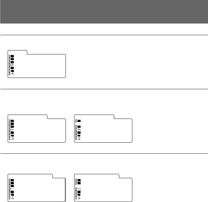
USER CONFIG 1/2, 2/2 menu
(USER CONFIG 1/2 menu) |
|
|
(USER CONFIG 2/2 menu) |
|
|||||||||||||
|
U S E R C O N F I G 1 / 2 |
|
|
|
U S E R C O N F I G 2 / 2 |
|
|||||||||||
|
|
|
|
|
· R G B / C O M P S E L |
C O M P |
|
|
|
|
|
|
|
|
|
xC A P T I O N |
O F F |
|
|
|
|
|
· 1 1 2 5 / 6 0 I S Y S |
1 0 8 0 |
|
|
|
|
|
|
|
|
|
· D E GA U S S D E L A Y |
0 |
|
|
|
|
|
|
|
|
|
|||||||||
|
|
|
|
|
|
|
|
|
|||||||||
|
|
|
|
|
· M A T R I X |
6 0 1 |
|
|
|
|
|
|
|
|
|
· MA R K E R P H A S E |
0 |
|
|
|
|
|
· C O M P L E VE L |
S M P T E |
|
|
|
|
|
|
|
|
|
· MA R K E R W I D T H |
0 |
|
|
|
|
|
· N T S C SE T U P |
0 |
|
|
|
|
|
|
|
|
|
|
|
|
|
|
|
|
· F O R M A T D I S P |
A U T O |
|
|
|
|
|
|
|
|
|
|
|
|
|
|
|
|
· L A N G UA G E |
E N G L I S H |
|
|
|
|
|
|
|
|
|
|
|
|
|
|
|
|
|
|
|
|
|
|
|
|
|
|
|
|
|
REMOTE 1/2 PARALLEL menu, 2/2 SERIAL menu
(REMOTE 1/2 PARALLEL menu) |
(REMOTE 2/2 SERIAL menu) |
|
|
|||||||||||||||
|
R E M O T E 1 / 2 P A R A L L E L |
|
R E M O T E 2 / 2 S E R I A L |
|
||||||||||||||
|
|
|
|
|
· 1 P I N |
L I N E A |
|
|
|
|
|
|
|
|
|
xS I N G L E A D D R E S S |
0 |
|
|
|
|
|
|
· 2 P I N |
L I N E B |
|
|
|
|
|
|
|
|
|
· GR O U P A D D R E S S |
0 |
|
|
|
|
|
|
|
|
|
|
||||||||||
|
|
|
|
|
|
|
|
|
||||||||||
|
|
|
|
|
· 3 P I N |
T A L L Y R |
|
|
|
|
|
|
|
|
|
· C H ( 1 – 4 ) C O N F I G |
C H 1 |
|
|
|
|
|
|
· 4 P I N |
T A L L Y G |
|
|
|
|
|
|
|
|
|
· I N P U T |
L I N E A |
|
|
|
|
|
|
· 6 P I N |
E X T S Y N C |
|
|
|
|
|
|
|
|
|
· AS P E C T |
|
4 : 3 |
|
|
|
|
|
· 7 P I N |
U ND E R S C A N |
|
|
|
|
|
|
|
|
|
· SC A N S I Z E |
N O R M A L |
|
|
|
|
|
|
· 8 P I N |
1 6 : 9 |
|
|
|
|
|
|
|
|
|
|
|
|
|
|
|
|
|
|
|
|
|
|
|
|
|
|
|
|
|
|
|
OPTION CONFIG menu
For details on the OPTION CONFIG menu screens, see page 21 (US).
KEY PROTECT menu
K E Y P R O T E C T
· K E Y P R O TE C T O F F
16 (US)

STATUS Menu
The STATUS menu is used to display the current status of the monitor. The following items are displayed:
•Signal format
•Color temperature
•Component level
•NTSC setup
•RGB/COMP select
•Option
COLOR TEMP/BAL
Menu
The COLOR TEMP/BAL menu is used for adjusting the picture white balance.
You need to use the measurement instrument to adjust the white balance.
COLOR TEMP
Select the color temperature from among D65, D93 and USER setting.
MANUAL ADJ
If you set the [COLOR TEMP] to USER setting, the item displayed is changed from blue to white, which means you can adjust the color temperature.
ADJUST GAIN…
Adjust the color balance (GAIN).
Select [ADJUST GAIN…]. The [ADJUST GAIN…] screen appears. Adjust the gain by pressing the UP or DOWN button.
ADJUST BIAS…
Adjust the color balance (BIAS).
Select [ADJUST BIAS…]. The [ADJUST BIAS…] screen appears. Adjust the bias by pressing the UP or DOWN button.
COPY FROM
If you select D65 or D93 with the UP or DOWN button, the white balance data for the selected color temperature will be copied in the user setting.
17 (US)

USER CONTROL 1/2, 2/2 Menu
The USER CONTROL 1/2, 2/2 menu is used for adjusting the picture.
Items that cannot be adjusted depending on the input signal are displayed in blue.
AUTO CHROMA/PHASE
Adjusts color intensity (CHROMA) and tones (PHASE).
AUTO ADJ VALUE
Selects ON or OFF of the Auto adjustment. When set to OFF, this parameter is reset to the factory setting. When set to ON the automatically adjusted value is enabled.
START…
Display the color bar signals (Full/SMPTE/EIA/HD) on the screen and press ENTER. The AUTO ADJUSTMENT screen starts. Exit from the AUTO ADJUSTMENT screen using the MENU button after finishing adjustment. When the adjustment is done correctly, the AUTO ADJ VALUE is automatically enabled.
Note
If you have selected the full color bars, enter eight color bars.
USER MEMORY
SAVE
Saves the current VOLUME, CONTRAST, PHASE, CHROMA or BRIGHT settings on the control panels. You can select MEMORY1 or MEMORY2 area to save the data.
LOAD
Loads the VOLUME, CONTRAST, PHASE, CHROMA or BRIGHT setting of the control panels from the setting saved in a memory described above. If you select Standard, the settings are reset to the standards.
SUB CONTROL
You can finely adjust the adjustment range of buttons on the right-side of the front panel; CONTRAST, PHASE, CHROMA and BRIGHT buttons.
CONTRAST
Adjusts the picture contrast. You can adjust the contrast from 0 to 100.
BRIGHT
Adjusts the picture brightness. You can adjust the brightness from –50 to +50.
CHROMA
Adjusts color intensity. The higher the setting, the greater the intensity.
The lower the setting, the lower the intensity. You can adjust the color intensity from 0 to 100.
PHASE
Adjusts color tones. The higher the setting, the complexion becomes greenish.
The lower the setting, the picture becomes purplish. You can adjust the color tones from –50 to +50.
APERTURE
Adjusts the picture sharpness. The higher the setting, the sharper the picture. You can adjust the color sharpness from OFF to 100.
18 (US)

USER CONFIG 1/2, 2/2 Menu
You can select a language, RGB and component. The settings in parentheses [ ] are factory settings.
RGB/COMP SEL
To monitor the signal fed through the RGB/ COMPONENT connectors, set the RGB or COMP (component) signal in this menu. Press the UP or DOWN button to select the RGB or COMP signal.
[COMP]
1125/60I SYS
Select the effective scanning lines for the 1125/60I signal input. Select 1080 or 1035 of the scanning lines. If the HD SDI is input, the system automatically selects the scanning line type.
[1080]
MATRIX
Applied to normal image signal, 15K or 31K component signals.
Press the UP or DOWN button to select 709 or 601.
[601]
COMP LEVEL
Select the component level from among three modes. N10/SMPTE for 100/0/100/0 signal
BETA 7.5 for 100/7.5/75/7.5 signal BETA 0 for 100/0/75/0 signal
[BETA 7.5]
NTSC SETUP
Select the NTSC setup level from two modes.
The 7.5 setup level is mainly used in North America. The 0 setup level is mainly used in Japan.
[7.5]
FORMAT DISP
Select the display mode of the signal format from among ON, OFF and AUTO.
[AUTO]
LANGUAGE
You can select the menu or message language from among six languages (Japanese, English, German, French, Italian, Spanish).
Select a language by pressing the UP or DOWN button, then press the ENTER button. The selected language is displayed.
[ENGLISH]
CAPTION
Select the caption display mode from among the followings:
OFF, CAPTION 1, CAPTION 2, TEXT 1 and TEXT 2.
[OFF]
DEGAUSS DELAY
Set the delay time of auto degaussing to start working after the power is turned on. The delay time can be set within 0 to 99 seconds.
[0]
LANDING
This menu is provided only for PVM-20L5.
If the color is not uniform even after you press the DEGAUSS button, you can adjust the landing so as to obtain color uniformity on this screen. [50] The following two methods are available to adjust the landing.
When the signals of the horizontal lines are input and displayed:
Press the UP or DOWN button until the lines are displayed on the screen as horizontally as possible. The horizontal lines can be adjusted within 0 to 100.
When the signals of the white color are input and displayed:
Press the UP or DOWN button until the white color on the screen become as uniform as possible. The level of the white color signals can be adjusted within 0 to 100.
MARKER PHASE
You can adjust the 4:3 marker position within –10 to +10.
[0]
MARKER WIDTH
You can adjust the 4:3 marker width within –10 to +10.
[0]
19 (US)

REMOTE 1/2
PARALLEL Menu
Select the PARALLEL REMOTE connector pins for which you want to change the function.
You can assign various functions to 1 to 4 pins and 6 to 8 pins. The following lists the functions you can assign to the pins.
• – – (“– –”: No function |
• UNDERSCAN |
is assigned.) |
• 16:9 |
• LINE A |
• EXT SYNC |
• LINE B |
• H/V DELAY |
• RGB/COMP |
• BLUE ONLY |
• OPTION A |
• MONO |
• OPTION B |
• 4:3 MARKER |
• TALLY RED |
• DEGAUSS |
• TALLY GREEN |
|
Note
If you use the PARALLEL REMOTE function, you need to connect cables. For more details, see page 25 (US).
REMOTE 2/2 SERIAL
Menu
When you control this unit by using the serial remote mode from the BVM series unit, set the monitor single address and group address, or the channel number you want to assign in this menu.
SINGLE ADDRESS
The following lists the functions that can be performed by a serial remote command from a BVM series unit:
• CONTRAST adjustment |
• Horizontal delay |
• BRIGHT adjustment |
button* |
• CHROMA adjustment |
• Vertical delay button* |
• PHASE adjustment |
• Monochrome button |
• Numeric keypad 1 |
• Aperture button |
button |
• 16:9 button |
• Numeric keypad 2 |
• SYNC button |
button |
• Blue only button |
• Numeric keypad 3 |
• Safe area button |
button |
• Degauss button |
• Numeric keypad 4 |
* The system of this unit |
button |
functions in the H/V |
• Underscan button |
DELAY mode. |
GROUP ADDRESS
Set the monitor group address number. You can set within 0 to 99.
CH(1-4) CONFIG
Set the channel numbers (1 to 4) that have been assigned to the direct keys in the BVM series unit. Select from among CH1, CH2, CH3 and CH4. You can set the channel for INPUT, ASPECT and SCAN SIZE.
INPUT
Sets the input system to the selected channels. Select from among LINE A, LINE B, RGB/COMP, OPTION A and OPTION B.
ASPECT
Sets the aspect ratio of the picture.
Select 16:9 or 4:3.
SCAN SIZE
Sets the size of a picture which is displayed by scanning the input signal.
Select UNDER or NORMAL.
BVM-Series PVM-14L5/20L5 PVM-14L5/20L5
Serial Remote Control Configuration Example
Note
If you perform a single control multiple times continuously in the serial mode, the remote state may be disabled. In this case, execute the same control command several times until the remote state is recovered.
20 (US)
OPTION CONFIG Menu
Sets the option boards installed in the rear. Depending on the installed board, the displayed screen may differ. If no board is installed, the item settings are not displayed. After assigning the input signal, adjust the monitor’s AUTO CHROMA/PHASE.
When installing the optional board BKM150CP:
O P T I O N C O N F I G
|
|
|
|
B K M – 1 5 0 C P |
|
|
|
|
|
S E R I A L |
x x x x x x x x |
|
|
|
|
||
|
|
|
|
||
|
|
|
|
F A N |
O K |
|
|
|
|
· F O R M A T |
S D T I – C P |
|
|
|
|
· A U D I O C H |
C H 1 + C H 2 |
|
|
|
|
· T I M E C O D E |
O F F |
|
|
|
|
|
|
FORMAT
Sets the signal type.
Select SDTI-CP or SDI.
AUDIO
Selects an audio channel. D1-SDI:
Select from among CH1+CH2 through CH15+CH16, or CH1 through CH16.
SDTI-CP:
Select from among CH1+CH2 through CH7+CH8, or CH1 through CH8.
The audio signal input to the OPTION AUDIO INPUT 1/2 jack is ignored.
TIME CODE
Selects the time code display. D1-SDI:
Select VITC, RP188 or OFF. SDTI-CP:
Select VITC, CP-TC1, CP-TC2, ES-TC1, ES-TC2 or OFF.
The following lists the abbreviations in the menu and their full names:
CP-TC1: SMPTE 331M System Item USER DATE/ TIME STAMP
CP-TC2: SMPTE331M System Item CREATION DATE/TIME STAMP
ES-TC1: SMPTE 328M MPEG ES Editing Information TIME CODE1
ES-TC2: SMPTE 328M MPEG ES Editing Information TIME CODE2
PR188: SMPTE RP188 Time Code
VITC: SMPTE 12M VITC, SMPTE 266M D-VITC
When installing the optional board BKM155DV:
O P T I O N C O N F I G
|
|
|
|
B K M – 1 5 5 D V |
|
|
|
|
|
S E R I A L |
x x x x x x x x |
|
|
|
|
||
|
|
|
|
||
|
|
|
|
F O R M A T |
D V |
|
|
|
|
· A U D I O C H |
C H 1 + C H 2 |
|
|
|
|
F A N |
O K |
|
|
|
|
|
|
|
|
|
|
|
|
AUDIO
Selects an audio channel.
Select from among CH1+CH2, CH3+CH4, CH1/3, CH2/4, CH1/3+CH2/4, or CH1 through CH4.
The audio signal input to the OPTION AUDIO INPUT 1/2 jack is ignored.
When installing the optional board BKM120D:
O P T I O N C O N F I G
B K M – 1 2 0 D |
|
S E R I A L |
x x x x x x x x |
When installing the optional board BKM142HD:
O P T I O N C O N F I G
|
|
|
|
|
B K M – 1 4 2 H D |
|
|
|
|
|
|
|
S E R I A L |
x x x x x x x x |
|
|
|
|
|
|
|
||
|
|
|
|
|
|
||
|
|
|
|
|
F A N |
O K |
|
|
|
|
|
|
|
|
|
|
|
|
|
|
|
|
|
|
|
|
|
|
|
|
|
|
|
|
|
|
|
|
|
When installing the optional board BKM129X:
O P T I O N C O N F I G
|
|
|
|
B K M – 1 2 9 |
X |
|
|
|
|
S E R I A L |
x x x x x x x x |
|
|
|
|
||
|
|
|
|
||
|
|
|
|
|
|
|
|
|
|
|
|
|
|
|
|
|
|
If the cooling fan in the BKM-142HD, BKM-150CP or BKM-155DV is stopped, the screen shows the following message in red “BKM-xxxxx FAN ERROR”. In this case, you cannot select Option A or Option B.
21 (US)

KEY PROTECT Menu |
|
Troubleshooting |
|
|
|
You can lock the settings so that they cannot be changed by an unauthorized user.
Select OFF or ON.
If you set ON, all items are displayed in blue, indicating the items are locked.
This section may help you isolate the cause of a problem and as a result, eliminate the need to contact technical support.
•The display is colored in green or purple. t
Select the correct input by pressing one of the buttons related to input.
•The unit cannot be operated. tThe key protection function works. Set the KEY PROTECT setting to OFF in the KEY PROTECT menu.
•The BKM-142HD, BKM-150CP or BKM-155DV has been installed. The error message “BKMxxxxx FAN ERROR” is displayed and you cannot select Option A or Option B. tRepair the BKMxxxxx.
22 (US)

Specifications
General
System
|
Total lines |
Active lines |
Frame |
Scanning |
Aspect |
|
|
System |
rate |
Standard |
|||||
per frame |
per frame |
format |
ratio |
||||
|
(Hz) |
|
|||||
|
|
|
|
|
|
||
|
|
|
|
|
|
|
|
575/50I (PAL) |
625 |
575 |
25 |
2:1 Interlace |
16:9/4:3 |
ITU 601 |
|
|
|
|
|
|
|
|
|
480/60I (NTSC) |
525 |
483 |
30 |
2:1 Interlace |
16:9/4:3 |
ITU 601 |
|
|
|
|
|
|
|
|
|
576/50P |
625 |
576 |
50 |
Progressive |
16:9/4:3 |
— |
|
|
|
|
|
|
|
|
|
480/60P |
525 |
483 |
60 |
Progressive |
16:9/4:3 |
SMPTE 293M |
|
|
|
|
|
|
|
|
|
1080/48I |
1125 |
1080 |
24 |
2:1 Interlace |
16:9 |
— |
|
|
|
|
|
|
|
|
|
1080/50I |
1125 |
1080 |
25 |
2:1 Interlace |
16:9 |
SMPTE 294M |
|
|
|
|
|
|
|
|
|
1035/60I |
1125 |
1035 |
30 |
2:1 Interlace |
16:9 |
BTA S-001B |
|
|
|
|
|
|
|
|
|
1080/60I |
1125 |
1080 |
30 |
2:1 Interlace |
16:9 |
SMPTE 274M/BTA S-001B |
|
|
|
|
|
|
|
|
|
720/60P |
750 |
720 |
60 |
Progressive |
16:9 |
SMPTE 296M |
|
|
|
|
|
|
|
|
PVM-14L5 |
|
CRT: |
HR Trinitron, SMPTE-C standard |
|
luminescent material |
Power: |
AC100 to 240V, 50/60Hz |
Power consumption: |
|
|
Maximum 120W, 1.2 to 0.6A |
|
(when the optional BKM-150CP |
|
has been installed) |
|
Standard: 110W, 1.1 to 0.5A |
|
(Without optional board, 720/60P |
|
input) |
Dimensions (max.): |
|
|
Approx. 346 × 280 × 424mm |
|
(13 5/8 × 11 1/8 × 16 3/4 inches) |
|
(w/h/d) |
Mass: |
Approx. 17kg (37 lb 8 oz) |
PVM-20L5 |
|
CRT: |
HR Trinitron, SMPTE-C standard |
|
luminescent material |
Power: |
AC100 to 240V, 50/60Hz |
Power consumption: |
|
|
Maximum 140W, 1.4 to 0.7A |
|
(when the optional BKM-150CP |
|
has been installed) |
|
Standard: 130W, 1.3 to 0.6A |
|
(Without optional board, 720/60P |
|
input) |
Dimensions (max.): |
|
|
Approx. 452 × 414 × 500mm |
|
(17 7/8 × 16 3/8 × 19 3/4 inches) |
|
(w/h/d) |
Mass: |
Approx. 31kg (68 lb 5 oz) |
Input/output connectors
Input
LINE A input connector
Y/C input 4-pin mini-DIN (1)
See the pin assignment
VIDEO input
BNC type (1) 1Vp-p ± 6dB negative synchronization
AUDIO input
Pin jack (1) –5dBu 47 kΩ or higher
LINE B input connector VIDEO input
BNC type (1) 1Vp-p ± 6dB negative synchronization
AUDIO input
Pin jack (1) –5dBu 47 kΩ or higher
RGB/Component input connector BNC type (3)
RGB input 0.7Vp-p ± 6dB (Sync On Green, 0.3Vp-p negative sync.)
Component input
0.7Vp-p ± 6dB (75% chrominance standard color bar signal)
AUDIO input
Pin jack (1) –5dBu 47 kΩ or higher
Externally synchronized input
BNC type (1) 0.3 to 8Vp-p
± bipolarity ternary or negative polarity binary
23 (US)

Specifications
Optional AUDIO input
Pin jack (2) –5dBu 47 kΩ or higher
Remote input Serial remote
D-Sub 9-pin (1) Parallel remote
Modular connector 8-pin (1)
Output
LINE A output connector
Y/C output 4-pin mini-DIN (1) Loop-through, with 75 Ω automatic terminal function
VIDEO output
BNC type (1) Loop-through, with 75 Ω automatic terminal function
AUDIO output
Pin jack (1) Loop-through
LINE B output connector VIDEO output
BNC type (1) Loop-through, with 75 Ω automatic terminal function
AUDIO output
Pin jack (1) Loop-through
RGB/Component output connector
BNC type (3) RGB/Component output Loop-through, with 75 Ω automatic
terminal function AUDIO output
Pin jack (1) Loop-through
Externally synchronized output
BNC type (1) Loop-through, with 75 Ω automatic terminal function
Remote output Serial remote
D-Sub 9-pin (1) Loop-through Built-in speaker output
0.8W (monaural)
Video signal
Frequency response
575/50I, 480/60I component inputs 50 Hz to 10 MHz (0 dB/–3 dB)
Models other than the above or RGB inputs
48 Hz to 24 MHz, (0 dB/ –3 dB) Aperture compensation1)
OFF: 0 dB
ON: 2 dB to 6 dB
575/50I, 480/60I inputs: 5 MHz Input other than the above: 16 MHz
Picture performance
Normal scan |
7% overscan of CRT effective |
|
|
screen area |
|
Underscan |
5% underscan of CRT effective |
|
|
screen area |
|
Linearity |
PVM-14L5 |
|
|
H: 4% or less |
|
|
V: 4% or less |
|
|
PVM-20L5 |
|
|
H: 5% or less |
|
|
V: 5% or less |
|
Color temperature |
|
|
|
D65, D93/USER (Adjustable color |
|
|
temperature: 5000K to 10000K) |
|
Convergence error |
|
|
|
PVM-14L5 |
|
|
Center: |
0.4mm (1/32 inch) |
|
|
or less |
|
Peripheral: 0.5mm (1/32 inch) |
|
|
|
or less |
|
PVM-20L5 |
|
|
Center: |
0.5mm (1/32 inch) |
|
|
or less |
|
Peripheral: 0.7mm (1/32 inch) |
|
|
|
or less |
.........................................................................................................................................................................................................
1) The aperture cannot be compensated for RGB input signals.
24 (US)
 Loading...