


COMMUNICATION SYSTEM
PCS-1
PCS-1P
SYSTEM INTEGRATION MANUAL 1st Edition (Version 2.2 and later)

! WARNING
This manual is intended for qualified service personnel only.
To reduce the risk of electric shock, fire or injury, do not perform any servicing other than that contained in the operating instructions unless you are qualified to do so. Refer all servicing to qualified service personnel.
! WARNUNG
Die Anleitung ist nur für qualifiziertes Fachpersonal bestimmt.
Alle Wartungsarbeiten dürfen nur von qualifiziertem Fachpersonal ausgeführt werden. Um die Gefahr eines elektrischen Schlages, Feuergefahr und Verletzungen zu vermeiden, sind bei Wartungsarbeiten strikt die Angaben in der Anleitung zu befolgen. Andere als die angegeben Wartungsarbeiten dürfen nur von Personen ausgeführt werden, die eine spezielle Befähigung dazu besitzen.
! AVERTISSEMENT
Ce manual est destiné uniquement aux personnes compétentes en charge de l’entretien. Afin de réduire les risques de décharge électrique, d’incendie ou de blessure n’effectuer que les réparations indiquées dans le mode d’emploi à moins d’être qualifié pour en effectuer d’autres. Pour toute réparation faire appel à une personne compétente uniquement.
PCS-1/1P
Table of Contents
1. |
Installation |
|
|
1-1. |
Caution on Installation ................................................................................ |
1-1 |
|
|
1-1-1. Lay Out the Videoconferencing Room ...................................... |
1-1 |
|
|
1-1-2. |
Operating Environment .............................................................. |
1-6 |
1-2. |
Flowchart of Installation ............................................................................. |
1-7 |
|
1-3. |
System Connections .................................................................................... |
1-8 |
|
|
1-3-1. When Used in LAN (100BASE-TX/10BASE-T) ...................... |
1-8 |
|
|
1-3-2. When Used in ISDN ................................................................... |
1-9 |
|
1-4. |
Initialization .............................................................................................. |
1-10 |
|
|
1-4-1. Inserting Batteries into the Remote Commander ..................... |
1-10 |
|
|
1-4-2. |
Turning On/Off the TV Monitor Together With the |
|
|
|
Communication Terminal ........................................................ |
1-11 |
|
1-4-3. Adjust the Volume of a Monitor Television ............................ |
1-12 |
|
|
1-4-4. Installing the Communication Terminal and Camera .............. |
1-12 |
|
|
1-4-5. |
Turning On ............................................................................... |
1-13 |
|
1-4-6. When the power is first turned on after installation ................. |
1-14 |
|
1-5. |
System Setting ........................................................................................... |
1-17 |
|
1-6. Flowchart of Opening Test ........................................................................ |
1-22 |
||
|
1-6-1. Dialing Procedure of ISDN ...................................................... |
1-23 |
|
|
1-6-2. Answering Procedure of ISDN ................................................ |
1-25 |
|
|
1-6-3. Dialing Procedure of LAN ....................................................... |
1-26 |
|
|
1-6-4. Answering Procedure of LAN ................................................. |
1-28 |
|
2. |
Maintenance |
|
2-1. Confirmation Procedure of Local Terminal Operation Using Self-Loop |
... 2-1 |
|
2-2. LAN Communication Test using Ping ........................................................ |
2-2 |
|
2-3. |
Locating the Components ........................................................................... |
2-3 |
2-4. |
Operation Log ............................................................................................. |
2-5 |
2-5. |
Updating of Software ................................................................................ |
2-15 |
|
2-5-1. Updating Using Memory Stick ................................................ |
2-15 |
2-6. |
Service Mode ............................................................................................ |
2-16 |
3. Compatibility in LAN Network |
|
|
3-1. |
Connection via Hub ..................................................................................... |
3-1 |
3-2. |
Connection via Router ................................................................................. |
3-3 |
3-3. |
Connection via DHCP ................................................................................. |
3-5 |
3-4. |
Connection via Gatekeeper ......................................................................... |
3-7 |
3-5. Connection via DHCP and Gatekeeper ....................................................... |
3-9 |
|
3-6. |
Connection beyond NAT .......................................................................... |
3-11 |
3-7. |
Connection using PPPoE ........................................................................... |
3-13 |
PCS-1/1P |
1 |
4. |
Technical Data |
|
|
4-1. PCS-1/1P Port Number Used ...................................................................... |
4-1 |
||
|
4-1-1. During P-P Connection (Default) ............................................... |
4-1 |
|
|
4-1-2. P-P Connection (Custom: When TCP port number is |
|
|
|
|
set to 3000 and UDP port number is set to 3100) ...................... |
4-1 |
|
4-1-3. During Use of Internal MCU Function (Default) ...................... |
4-2 |
|
|
4-1-4. |
During Use of Internal MCU Function (Custom: When TCP |
|
|
|
port number is set to 3000 and when UDP port number is set |
|
|
|
to 3100) ...................................................................................... |
4-2 |
4-2. Setting of PCS-1 and HUB ......................................................................... |
4-3 |
||
4-3. Audio and Video Input/Output Characteristics ........................................... |
4-3 |
||
|
4-3-1. Audio input/output characteristics of PCS-1/1P ........................ |
4-3 |
|
|
4-3-2. Video input/output characteristics of PCS-1/1P ........................ |
4-3 |
|
4-4. Audio Selection List of PCS-1/1P ............................................................... |
4-4 |
||
4-5. |
Remote Motion Picture Display during Multipoint |
|
|
|
Connection of PCS-1/1P ............................................................................. |
4-6 |
|
|
4-5-1. |
Remote Motion Picture Displayed at Each Point in |
|
|
|
Audio Detection Mode ............................................................... |
4-6 |
|
4-5-2. |
Remote Motion Picture at Each Point in Broadcast |
|
|
|
Selection Mode ........................................................................... |
4-6 |
|
4-5-3. Remote Motion Picture at Each Point in Split Mode ................. |
4-7 |
|
4-6. Display Transition List of PCS-1/1P ........................................................... |
4-9 |
||
4-7. Priority Level List of Video and Audio Codec ......................................... |
4-11 |
||
4-8. |
Conference Connection Format and Its Corresponding |
|
|
|
Usable Codec List ..................................................................................... |
4-12 |
|
2 |
PCS-1/1P |

Section 1
Installation
1-1. Caution on Installation
1-1-1. Lay Out the Videoconferencing Room
Arrange it in consideration of the space of a camera and microphone when laying out the videoconferencing room.
Camera Range

 represents the shooting area of the camera when the zoom has been extended fully.
 indicates the shooting area of the camera when the left/right angling function is fully utilized. Use the measurements below as a guide for the layout of your videoconference room.
Top view (horizontal range at maximum zoomout)
1.5 m (4.92 ft)
100d  100d
100d
4 m |
65d |
(13.12 ft) |
5.1 m (16.73 ft)
Side view (vertical range at maximum zoom-out)
|
25d |
3.1 m |
42d |
(8.41 ft) |
|
|
25d |
|
4 m (13.12 ft) |
PCS-1/1P |
1-1 |

Highly directional range of microphone
The ideal directional range of a microphone is shown below. The numeric value is a rough standard. Use the value as the reference of the videoconferencing room used.
1: For internal microphone
90d
2 m
2: For extension microphone (PCS-A300)
0.5 to 1 m
120d
3: For extension microphone (PCS-A1)
0.5 to 1.2 m
1-2 |
PCS-1/1P |
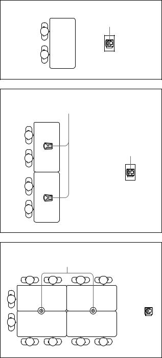
The microphone built in the PCS-C1/C1P Camera Unit is assumed to be used to conduct a conference among about three participants. You can connect the optional PCS-A1 or PCS-A300 microphone to the System, allowing more persons to participate in the conference.
Microphone layout examples
Microphone built in the PCS-1/1P
PCS-1/1P
PCS-A300 microphones
PCS-A300
PCS-1/1P
PCS-A1 microphones
PCS-A1
PCS-1/1P
Notes on installation of the microphones
. Install microphone about 50 cm away from the participants.
. Install the speakers behind the microphones.
. Place the microphone in a quiet, echo-free location.
. Install microphones away from equipment that may cause noise.
.Avoid covering a microphone with paper, etc., or moving it. If you do either, extreme noise and echo may be heard temporarily by the remote party. In this case, wait until the echo disappears.
|
|
|
|
|
|
|
|
|
|
|
|
PCS-1/1P |
1-3 |
||

Installation of document stand
a.Adjust the direction of an infrared light emitter.
Install so that the infrared light emitter of the document stand is linear in direction with the infrared photosensor of PCS-1/1P when the video signal input to a document stand is transmitted to PCS-1/1P using an infrared video transmission function. The range in which infrared rays reach is a maximum of about 5 m.
Connect it with PCS-1/1P using a MONITOR OUT terminal when the infrared light emitter is used in excess of about 5 m.
PCS-1/1P
Infrared rays
Infrared photosensor
Document stand
Infrared light emitter
 The blue line in the light emitter indicates the direction of infrared rays.
: Adjustment in vertical direction
: Adjustment in horizontal direction
1-4 |
PCS-1/1P |

b.Installation range (Reference)
If an image is disturbed in the range shown below, bring it near PCS-1/1P with the infrared light emitter of a documents stand turned toward PCS-1/1P.
Infrared light emitter
|
PCS-1/1P |
Infrared |
|
light emitter |
|
15d |
|
5 m |
30d 45d |
|
|
|
Infrared |
Infrared |
photosensor |
|
|
light emitter 3.5 m |
2.5 m |
m
.Install so that the infrared light emitter of a document stand is linear in direction with the infrared photosensor of PCS-1/1P. Do not put an object that interrupts transmission. When the direction of the
infrared light emitter is shifted by five degrees or more, normal reception cannot be carried out, that is, an image is disturbed or stands still.
.Multiple document stands cannot be used at the same time. Infrared rays interfere and any signal cannot be received.
.The resolution of an image deteriorates when a video signal is transmitted using an infrared video transmission function. Connect the infrared light emitter with PCS-1/1P using a MONITOR OUT
terminal when you do not want to deteriorate the resolution.
.Connect the infrared light emitter with PCS-1/1P using a MONITOR OUT terminal when an infrared video transmission function cannot be used due to the situation of a videoconferencing room.
.An image may be disturbed when other infrared light emitters are used or when a remote controller is used near the photosensor. Stop the use of other infrared light emitters or connect them with PCS-1/1P using a MONITOR OUT terminal.
PCS-1/1P |
1-5 |

1-1-2. Operating Environment
Layout Considerations
. Avoid having large, moving objects, especially people, behind the participants, as the quality of the picture transmitted to the remote party will deteriorate.
.Do not seat participants in front of a wall with fine stripe patterns.
. Choose a room where echo will not occur.
. Do not install the system near noise sources such as air conditioners or copy machines.
.Avoid placing the system in a room where there are the speakers used for an in-house broadcasting system.
Lighting Considerations
Do not point the camera toward a window where sunlight comes in as back lighting may decrease the contrast. If it is necessary, cover the window with a thick curtain.
Adjust room lighting so that it falls on the participants. Avoid direct light on the TV monitor. Light intensity on faces should be about 300 lux or more.
If an inverter type or brightness-adjustable type of fluorescent lamp is used, the sensitivity of the Remote Commander may deteriorate.
Installing the Communication Terminal and Camera
|
|
|
|
|
|
|
|
|
|
|
|
|
|
|
|
|
|
|
|
|
|
|
|
|
|
|
|
|
|
|
|
|
|
|
|
|
|
|
|
|
|
|
|
|
|
|
|
|
|
|
|
|
|
|
|
|
|
|
|
|
|
|
|
|
|
|
|
|
|
|
|
|
|
|
|
|
|
|
|
|
|
|
|
|
|
|
|
|
|
|
|
|
|
|
|
|
|
|
|
|
|
|
|
|
|
|
|
|
|
|
|
|
|
|
|
|
1-6 |
|
|
|
|
|
|
|
|
|
|
|
PCS-1/1P |
1-2. Flowchart of Installation
Place used
Unpacking
Check of supplied accessories
Power and cable connection, and preparation
Start the power of the system and initialize.
Initialize the related block.
End
<Refer to “1-1. Caution on Installation” on page 1-1.>
<Refer to “1-3. System Connections” on page 1-8.>
<Refer to “1-4. Initialization” on page 1-10.>
<“1-5. System Setting” on page 1-17.>
PCS-1/1P |
1-7 |
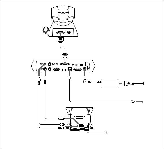
1-3. System Connections
This section describes the typical system connections. m
. Be sure to turn off all the equipment before making any connections.
.Do not connect/disconnect the camera cable with the power on. Doing so may damage the Camera Unit or Communication Terminal.
.For safety, do not connect the 100BASE-TX/10BASE-T connector to a network that applies an excess voltage via the 100BASE-TX/10BASE-T connector
1-3-1. When Used in LAN (100BASE-TX/10BASE-T)
PCS-C1/C1P Camera Unit
TERMINAL VISCA OUT
|
to TERMINAL |
|
PCS-P1/P1P |
Camera cable* |
|
|
||
Communication |
to CAMERA UNIT |
|
Terminal |
||
|
AUDIO OUT |
AUX1–VIDEO IN–AUX2 |
AUDIO IN |
CAMERA UNIT |
MIC |
ISDN UNIT |
WHITE |
||
|
|
|
|
|
(PLUG IN POWER) |
|||
|
|
|
|
|
1 |
2 |
|
BOARD |
(MIXED) |
VIDEO OUT |
|
|
|
100BASE-TX |
|
|
DC 19.5V |
|
|
|
|
|
|
|||
AUX |
MAIN– MONITOR– SUB |
RGB OUT |
|
10BASE-T |
|
DSB |
|
|
|
|
|
|
|
IR OUT |
|
|
|
|
|
|
|
1 |
2 |
|
|
|
to AUDIO |
to VIDEO |
to DC19.5 V |
Power cord* |
|
|
|
|||
OUT |
OUT |
|
|
|
|
MONITOR |
to 100BASE-TX/ |
|
|
|
MAIN |
PCS-AC195 |
to wall outlet |
|
|
10BASE-T |
|||
|
|
|
||
|
|
AC adaptor |
|
|
|
|
|
|
|
Audio |
S-video |
UTP cable (category 5, straight)** |
|
|
connecting |
connecting |
TV monitor** |
|
|
cable* |
cable* |
|
to LAN |
|
to S-video
input |
|
to audio input |
to a wall outlet |
* supplied |
|
**not supplied |
|
1-8 |
PCS-1/1P |

1-3-2. When Used in ISDN
n
Do not connect/disconnect the camera cable or the interface cable with the power on. Doing so may damage the Camera Unit, Communication Terminal or ISDN Unit.
PCS-C1/C1P Camera Unit
TERMINAL VISCA OUT
|
to TERMINAL |
|
PCS-P1/P1P |
Camera cable* |
|
|
||
Communication |
to CAMERA UNIT |
|
Terminal |
||
|
AUDIO OUT |
AUX1–VIDEO IN–AUX2 |
AUDIO IN |
CAMERA UNIT |
MIC |
ISDN UNIT |
WHITE |
||
|
|
|
|
|
(PLUG IN POWER) |
|||
|
|
|
|
|
1 |
2 |
|
BOARD |
(MIXED) |
VIDEO OUT |
|
|
|
100BASE-TX |
|
|
DC 19.5V |
|
|
|
|
|
|
|||
AUX |
MAIN– MONITOR– SUB |
RGB OUT |
|
10BASE-T |
|
DSB |
|
|
|
|
|
|
|
IR OUT |
|
|
|
|
|
|
|
1 |
2 |
|
|
|
to AUDIO |
to VIDEO |
to DC19.5 V |
|
|
|
Power cord* |
||||
to ISDN |
|
|
|
|
||||||
OUT |
OUT |
UNIT |
|
|
|
|
|
|
|
|
|
|
MONITOR |
|
|
|
|
to a wall outlet |
|||
|
|
MAIN |
|
PCS-AC195 |
|
|||||
|
|
|
|
|
|
|
|
|||
|
|
|
Interface cable |
|
|
|
|
|
||
|
|
|
AC adaptor |
|
|
|
|
|
||
|
|
(supplied with the PCS-B768) |
|
|
|
|
|
|
|
|
|
|
|
|
to |
Front |
|
|
|
|
|
|
|
|
|
TERMINAL |
|
|
|
|
|
|
|
|
|
|
|
|
|
|
|
|
|
Audio |
S-video |
|
|
1 |
2 |
3 |
4 |
5 |
6 |
|
|
|
|
|
|
|
|
|
|||
connecting |
connecting |
PCS-B768 ISDN Unit** |
|
|
|
|
|
|
||
cable |
* |
* |
|
|
|
|
|
|
||
|
cable |
|
|
to ISDN 1-6 |
|
|
|
|||
|
|
|
|
|
|
|
|
|||
|
|
|
TV monitor** |
|
ISDN modular |
|
to ISDN |
|||
|
|
|
|
|
|
|
||||
|
|
|
|
|
cable** |
|
|
|
||
|
|
to S-video |
|
|
|
|
|
|
|
|
|
|
input |
|
|
|
|
|
|
|
|
|
|
to audio input |
|
|
to a wall outlet |
|
|
|||
* supplied |
|
|
|
|
|
|
|
|
|
|
** not supplied |
|
|
|
|
|
|
|
|
|
|
PCS-1/1P |
1-9 |

1-4. Initialization
1-4-1. Inserting Batteries into the Remote Commander
Most of the operations with the Video Communication System can be controlled with the supplied Remote Commander.
1. Remove the battery compartment cover.
2.Insert two size AA (R6) batteries (supplied) with correct polarities into the battery compartment.
n
Be sure to insert the batteries _side first. Inserting them forcibly +side first may damage the insulated film covering the batteries and cause a short circuit.
3. Replace the cover. m
Battery life
When the Remote Commander does not function properly, replace both the batteries with new ones.
Notes on batteries
. To avoid damage from possible battery leakage or corrosion, observe the following:
. Make sure to insert the batteries with the polarities in the correct direction.
. Do not mix old and new batteries, or different types of batteries.
. Do not attempt to charge the batteries.
.If you do not intend to use the Remote Commander for a long period of time, remove the batteries.
.If battery leakage occurs, clean the battery compartment and replace all the batteries with new ones.
1-10
PCS-1/1P
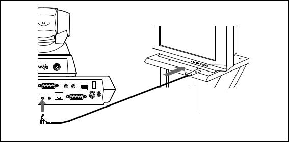
1-4-2. Turning On/Off the TV Monitor Together With the Communication
Terminal
If you use a Sony TV, insert the IR repeater under the remote sensor of the TV. Once you set the IR repeater, the TV will turn on or go to standby together with the Communication Terminal when you press the I/O button on the supplied Remote Commander.
|
|
|
|
TV monitor |
CAMERA UNIT |
MIC |
ISDN UNIT |
WHITE |
|
|
(PLUG IN POWER) |
|||
|
1 |
2 |
|
BOARD |
|
100BASE-TX |
|
|
DC 19.5V |
|
10BASE-T |
|
DSB |
|
|
IR OUT |
|
|
Remoted sensor |
1 |
2 |
|
|
|
|
|
|
|
|
|
|
|
|
IR repeater (supplied) |
to IR OUT |
|
|
|
|
n
If the TV monitor is not turned on by pressing the I/O button on the Remote Commander, change the “IR Repeater Mode” setting in the General Setup menu.
For details on the “IR Repeater Mode” setting, see “General Setup Menu” on page 1-18.
PCS-1/1P |
1-11 |

1-4-3. Adjust the Volume of a Monitor |
1-4-4. Installing the Communication |
Television |
Terminal and Camera |
Adjust the television side after the volume is adjusted on the PCS-1/1P side.
1.Press the volume/bright button of a remote controller and adjust so that the volume adjustment bar is in the center position
2.Adjust the volume of a monitor television.
Set to the volume in which the remote voice can be heard well.
After adjustment is completed, adjust the volume on the PCS-1/1P side.
You can fix the Communication Terminal or the Camera to your chosen place of installation using the supplied Velcro.
1.Stick the supplied Velcro to the bottom of the Communication Terminal or Camera.
Bottom of the Communication
Terminal
Bottom of the Camera Unit
2.Stick another piece of Velcro to the installation place.
3.Install the Communication Terminal or the Camera on the installation place by securing the two pieces of Velcro.
1-12 |
PCS-1/1P |

1-4-5. Turning On
1.Turn on the TV monitor.
If the IR repeater is installed in the TV monitor, set the TV monitor to standby mode. The TV monitor will turn on simultaneously when the Communication Terminal is turned on.
2.Turn on the power of any other equipment to be used for the videoconference.
3.Set the power switch on the right side of the Communication Terminal to the on position (I).
Power switch
POWER indicators (Light in green.)
The Communication Terminal turns on after a while. Three indicators on the front of the Communication Terminal and the POWER indicator on the camera light, then only the POWER indicators on both units remain on in green. The launcher menu will appear on the monitor screen and the picture shot by the local camera will also appear in the launcher menu.
Launcher menu
Connect |
|
Phone Book |
|
Dial |
|
Menu |
Angle Adj. |
Show Help |
|
IP:0.0.0.0 |
ISDN:012345678912 |
Video:Main |
Audio:MIC(INT)+AUX |
m
. After the power is turned on, the camera moves automatically for trial operation. Be careful not to catch your finger.
.If you use force to prevent the camera moving, it may not resume moving and not output a signal to the
Communication Terminal. In this case, turn off the Terminal, and turn it on again.
.When you turn on the power of the Communication Terminal for the first time after installation, the setup
wizard will appear after the self-diagnosis is completed. Set up your system following the wizard.
.For setups using the wizard, see “Setting Up the System for the First Time - Initial Setup Wizard” on page 1-14.
Standby Mode Function
To save power the Communication Terminal will enter standby mode if you do not operate it for a specified period of time.
When the Communication Terminal is in standby mode, the POWER indicator lights in orange. Once the Communication Terminal receives a call, the standby mode is automatically released.
To release the standby mode
Press the I/O button on the Remote Commander.
To specify the standby time
Specify the time that you want the system to remain on before entering into standby mode (1 to 99 minutes) using “Standby Time” in the General Setup menu. If you do not want the system to enter the standby mode, set “Standby Mode” in the General Setup menu to “Off”.
For the “Standby Time” and “Standby Mode” settings, see
“General Setup Menu” on page 1-18. m
.The POWER indicator on the camera goes off when the system enters standby mode.
.If you use a Sony TV monitor with the IR repeater installed under the remote sensor, the TV monitor will enter standby mode together with the Communication Terminal.
PCS-1/1P |
1-13 |

1-4-6. When the power is first turned on after installation
When the power is first turned on after installation, the wizard for initialization is displayed if self-diagnosis is completed. Register according to the wizard.
The items set according to the wizard can also be later changed on the menu screen.
n
The wizard for initialization is also displayed when ISDN unit PCS-B384 or PCS-B768 is newly installed after system installation. Similarly, register according to the wizard in this case.
1. Press the ↑ and ↓ buttons of a remote controller and select the language displayed in a menu or message.
Language:
You can select the desired language from English, French, German, Japanese, Spanish, Italian, Simplified Chinese, PORT (Portuguese), Traditional Chinese, and Korean*.
*Korean is added by upgrading.
Language Setup Wizard |
|
|
Language |
English |
|
|
Next |
Cancel |
2. Press the ↑ , ↓ , ← , and → buttons of a remote controller and click the “Next” button. Press the Enter button.
The monitor setting wizard is displayed. n
The monitor setting wizard is set when two or more monitors are connected to this unit. When only one monitor television is connected, select “Next” and proceed to step 5.
3.Set a monitor that outputs a signal. n
Notice that any menu screen is not displayed on monitors other than the set monitor when “Monitor output” is set.
ISDN Setup Wizard |
|
|
Country/Region |
USA |
|
Country/Region Code |
1 |
|
Protocol |
National ISDN |
|
Previous |
Next |
Cancel |
Dual monitor:
Sets whether to use one monitor for a motion picture monitor using a dual monitor function when two monitors are connected.
ON:
Set when using a dual monitor function. A still picture, computer picture, or whiteboard picture is displayed in the second monitor.
OFF:
Set when not using a dual monitor function. Monitor output (or Sub-monitor output): Select whether to output a signal to the monitor
connected to which output terminal. The “Monitor output” is changed to “Sub-monitor output” when “Dual monitor” is set to “ON”. In this case, select whether to output a signal to the sub-monitor (the second monitor) connected to which output terminal.
RGB of main unit:
Set when outputting a signal from the RGB OUT terminal of a communication terminal.
DSB RGB:
Set when outputting a signal from the RGB OUT terminal of a data solution box.
VIDEO of main unit:
Set when outputting a signal from the VIDEO OUT MONITOR MAIN or SUB terminal of a communication terminal.
1-14 |
PCS-1/1P |

4. Press the ↑ , ↓ , ← , and → buttons of a remote controller and click the “Next” button. Press the Enter button.
The ISDN setting wizard is displayed when ISDN unit PCS-B384 or PCS-B768 is connected.
The LAN setting wizard is displayed when an ISDN unit is not connected. Proceed to step 11.
5.Set the country, region, and protocol in which an ISDN line is used.
Country/region:
Select the country or region in which this unit is used. Select “Japan” when you use this unit in Japan.
Country/region No.:
Enter the country, region’s national number, or region number in which this unit is used.
Enter “81” when you use this unit in Japan. (“81” is automatically displayed when you select “Japan” in “Country/region”.)
Protocol:
Select the protocol of the ISDN line used. Select
“NTT” when you use this unit in Japan.
6. Press the ↑ , ↓ , ← , and → buttons of a remote controller and click the “Next” button. Press the Enter button.
7.Enter the telephone number of an ISDN line that this unit uses.
For one line, enter the same number in columns A1 and A2.
Area Code |
Local Number |
A1
A2
B1
B2
C1
C2
Previous |
Next |
Cancel |
Area code:
Enter the area code.
Do not enter the first “0” of an area code.
Local code:
Enter the local code. n
Select a blank column and press the Enter button of a remote controller. The setting contents of an item in
the above column are then copied.
PCS-1/1P
n
During use of ISDN unit PCS-B384, enter telephone numbers in columns B1 to C2 when two or three ISDN lines are connected.
During use of ISDN unit PCS-B768, enter telephone numbers in columns B1 to F2 when two to six ISDN lines are connected. To display columns D1 to F2, select “Next” and press the Enter button.
8. Press the ↑ , ↓ , ← , and → buttons of a remote controller and click the “Next” button. Press the Enter button.
9.Enter a sub-address.
In the sub-address, only numeric characters are valid. For one line, enter the same number in columns A1 and A2.
Sub Address
A1
A2
B1
B2
C1
C2
Previous |
Next |
Cancel |
n
During use of ISDN unit PCS-B384, enter subaddresses in columns B1 to C2 when two or three ISDN lines are connected.
During use of ISDN unit PCS-B768, enter subaddresses in columns B1 to F2 when two to six ISDN lines are connected. To display columns D1 to F2, select “Next” and press the Enter button.
10. Press the ↑ , ↓ , ← , and → buttons of a remote controller and click the “Next” button. Press the Enter button.
The LAN setting wizard is then displayed. n
When you do not use LAN, select “Next” and display a confirmation message. After that, proceed to step 13.
1-15

11. Set the following items on LAN.
LAN Setup Wizard |
|
|
|
DHCP Mode |
Auto |
|
|
Host Name |
|
|
|
IP Address |
. |
. |
. |
Network Mask |
. |
. |
. |
Gateway Address |
. |
. |
. |
DNS Address |
. |
. |
. |
Previous |
Next |
|
Cancel |
DHCP mode:
Sets DHCP (Dynamic Host Configuration Protocol).
AUTO:
Acquires an IP address, network mask, gateway address, and DNS address automatically.
OFF:
Sets DHCP to “OFF”. Enter an IP address, network mask, gateway address, and DNS address when you set DHCP to “OFF”.
Host name:
Enter a host name.
IP address:
Enter the IP address of this unit.
Network mask:
Enter a network mask.
Gateway address:
Enter a default gateway address.
DNS address:
Enter a DNS (Domain Name System) server address. n
The automatically acquired IP address can be confirmed in a launcher menu or information menu when the “DHCP mode” is set to “AUTO”.
Consult the network administrator when you cannot understand the method of setting on LAN.
12. Press the ↑ , ↓ , ← , and → buttons of a remote controller and click the “Next” button. Press the Enter button.
A confirmation message is then displayed.
13. Press the ↑ , ↓ , ← , and → buttons of a remote controller and click the “Save” button. Press the Enter button.
Save
Previous Cancel
The setting is then saved.
To stop the setting
Press the ↑ , ↓ , ← , and → buttons of a remote controller and click the “Cancel” button. Press the Enter button.
To return to the preceding wizard
Press the ↑ , ↓ , ← , and → buttons of a remote controller and click the “Return” button. Press the Enter button.
1-16 |
PCS-1/1P |
1-5. System Setting
The contents of a setting menu are shown in the table below. Change the setting as required.
*For the -marked initial value, the value input in the initialization wizard (Section 1-4-6) is set.
|
Item |
|
Contents of setting |
Initial value |
|
|
|
|
|
Dial Setup |
Page |
Line I/F |
Select the line interface [LAN, ISDN, or ISDN (Telephone)] used. |
LAN |
|
1/4 |
Bonding |
Select the bonding mode in which the remaining lines can also be connected by |
Auto |
|
|
|
only dialing one line when multiple ISDN lines are used. Select “On” when |
|
|
|
|
connecting a line in the bonding mode. Select “Auto” when automatically |
|
|
|
|
adjusting a line to the remote party. |
|
|
|
Number of Lines |
Select the number of ISDN lines used during dialing of ISDN from 1B (64K), 2B |
12B (768K) |
|
|
|
(128K), 3B (192K), 4B (256K), 5B (320K), 6B (384K), 8B (512K), or 12B |
|
|
|
|
(768K). |
|
|
|
LAN Bandwidth |
Set the bandwidth (bit rate) when communicating via a LAN line. |
1024Kbps |
|
|
Prefix |
Set the prefix number used when connecting using an ISDN line. |
None |
|
|
Restrict |
Select the transmission rate (Auto or 56K) when connecting using an ISDN line. |
Auto |
|
|
|
In a few countries (America, etc.) and regions, two types of rates (64 Kbps and |
|
|
|
|
56 Kbps) are used. Usually, select “Auto” as the transmission rate of ISDN. |
|
|
|
|
|
|
|
Page |
Video Mode |
Select a video coding system. |
All capabilities |
|
2/4 |
Video Frame |
Select the maximum number of video transmission frames (15 fps or 30 fps). |
15fps |
|
|
Audio Mode |
Select an audio coding system. |
All capabilities |
|
|
Far End Camera |
Set to “On” when controlling the camera on the remote party. Set to “Off” when |
On |
|
|
Control |
not controlling it. |
|
|
|
|
|
|
|
|
T.120 Data |
Set to “On” when making the data conference conforming to T.120 using |
Off |
|
|
|
NetMeeting. Set to “Off” when not making it. |
|
|
|
H.239 |
Set to “On” when using the dual video presentation mode based on the H.239 |
On |
|
|
|
standard. Set to “Off” when not using it. |
|
|
|
|
|
|
|
Page |
Prefix -A/-B/-C |
Set the prefix (dial number). |
Blank |
|
3/4 |
|
|
|
|
|
|
|
|
|
Page |
Telephone Mode |
Select the voice compression system during voice meeting. |
Auto |
|
4/4 |
More Options |
Set to “On” when you want to set the items in the dial setup menu for each dial |
Off |
|
|
Enable |
list. Set to “Off” when you do not want. |
|
|
|
|
|
|
|
|
User Name Input |
Set to “On” when recording the user name in a communication log before |
Off |
|
|
|
communication. Set to “Off” when not recording it. |
|
Answer Setup |
Page |
Auto Answer |
Select “Auto Answer” when automatically performing connection during |
Auto Answer |
|
1/2 |
|
reception of an answering call from the remote party. Select “Off” when |
|
|
|
|
confirming connection. |
|
|
|
Number of Lines |
Select the number of ISDN lines used during answering of ISDN from 1B (64K), |
12B (768K) |
|
|
|
2B (128K), 3B (192K), 4B (256K), 5B (320K), 6B (384K), 8B (512K), or 12B |
|
|
|
|
(768K). |
|
|
|
Restrict |
Select the transmission rate (Auto or 56K) when connecting (answering) using |
Auto |
|
|
|
an ISDN line. In a few countries (America, etc.) and regions, two types of rates |
|
|
|
|
(64 Kbps and 56 Kbps) are used. |
|
|
|
|
Usually, select “Auto” as the transmission rate of ISDN. |
|
|
|
LAN Bandwidth |
Set the bandwidth (bit rate) when communicating (incoming) via a LAN line. |
1024Kbps |
|
|
ISDN MSN |
Select “On” when employing multiple subscriber numbers during connection |
Off |
|
|
|
(answering) using an ISDN line. Select “Off” when not employing them. |
|
|
|
|
|
|
|
Page |
Video Mode |
Select a video coding system. |
ALL |
|
2/2 |
Video Frame |
Select the maximum number of video transmission frames (15 fps or 30 fps). |
15fps |
|
|
Audio Mode |
Select an audio coding system. |
ALL |
|
|
Far End Camera |
Set to “On” when controlling the camera on the remote party. Set to “Off” when |
On |
|
|
Control |
not controlling it. |
|
|
|
T.120 Data |
Set to “On” when making the data conference conforming to T.120 using |
Off |
|
|
|
NetMeeting. Set to “Off” when not making it. |
|
|
|
|
|
|
|
|
H.239 |
Set to “On” when using the dual video presentation mode based on the H.239 |
On |
|
|
|
standard. Set to “Off” when not using it. |
|
PCS-1/1P |
1-17 |
|
Item |
|
Contents of setting |
Initial value |
|
|
|
|
|
General Setup |
Page |
Terminal Name |
Enter the terminal name to be notified to MCU. |
PCS-1 |
|
1/4 |
Dual Monitor |
Set to “On” when using a dual monitor function with the two monitors |
Off |
|
|
|
connected. |
|
|
|
|
|
|
|
|
Monitor Output |
Select whether a signal should be output to the monitor connected to which |
VIDEO OUT |
|
|
(Sub-Monitor |
output terminal. When “Dual Monitor” is set to “On”, the menu is changed to |
|
|
|
Output) |
“Sub-Monitor Output”. Select whether a signal should be output to the sub- |
|
|
|
|
monitor connected to which output terminal. |
|
|
|
Standby Mode |
Set to “On” when using the standby mode. Set to “Off” when not using it. |
Off |
|
|
Standby Time |
Set the time (1 to 99 minutes) required until the unit is put into the standby mode |
|
|
|
|
when the standby mode is set to “On”. |
|
|
|
Time Display |
Set to “On” when displaying the elapsed time in the upper-right position of the |
On |
|
|
|
screen during the conference. Set to “Off” when not displaying it. |
|
|
|
|
|
|
|
Page |
Clock Set |
Set the current date and time. |
|
|
2/4 |
Last Number |
Set to “On” when registering the remote user in the Phone Book after a |
On |
|
|
Registration |
conference is terminated. Set to “Off” when not registering it. |
|
|
|
|
|
|
|
|
T.120 PC Address |
Enter the IP address of the computer used when the data conference conforming |
Blank |
|
|
|
to T.120 is made using NetMeeting. |
|
|
|
|
|
|
|
|
Whiteboard |
Select whether to attach the optional mimio Xi vertically or horizontally on the |
Vertical |
|
|
Attachment |
whiteboard. |
|
|
|
Whiteboard Size |
Select the size (height xwidth) of the whiteboard used. |
3’0”x4’0” |
|
|
Whiteboard |
Select whether to display the whiteboard size in inches or meters. |
Inches |
|
|
Measurement Size |
|
|
|
Page |
Language |
Select the language of the menu and message displayed on the screen. |
English |
|
3/4 |
IR Repeater Mode |
Select the mode for putting the monitor into the standby state or turning on the |
MODE1 |
|
|
|
power when a Sony’s monitor is used. Usually, set to “MODE 1”. |
|
|
|
Control by Far End |
Set to “On” when receiving the camera control command from the remote party. |
On |
|
|
|
Set to “Off” when not receiving it. |
|
|
|
|
|
|
|
|
Character Input |
Select whether to display the balloon help appearing when entering characters or |
On |
|
|
Help |
numeric characters. |
|
|
|
|
|
|
|
|
Memory Stick |
Execute the format of the Memory Stick. |
|
|
|
Format |
|
|
|
Page |
Video Input |
The input device names displayed in a launcher menu or video input select menu |
All blanks |
|
4/4 |
Selection Name |
can be changed to arbitrary names, respectively. |
|
|
|
.Main |
|
|
|
|
.Object |
|
|
|
|
.AUX1 |
|
|
|
|
.AUX2 |
|
|
Audio Setup |
Page |
Input Select |
Select the audio input (MIC, AUX, or MIC +AUX). |
MIC |
|
1/2 |
Mic Selection |
Select the microphone used (Internal, External, or DSB MIC). |
Internal |
|
|
CTE |
Select whether to use communication transducer CTE-600 and select the input |
Off |
|
|
|
terminal to be connected. Select “Off” when not using CTE-600. Select “AUX” |
|
|
|
|
when inputting to the AUDIO IN terminal of the main unit and select “DSB |
|
|
|
|
AUX IN” when inputting to the AUX IN terminal of a data solution box. |
|
|
|
|
* When CTE-600 is set so that it is used, “Input Select”, “Mic Select”, and |
|
|
|
|
“Echo Canceller” are automatically determined and cannot be changed. |
|
|
|
|
|
|
|
|
Echo Canceller |
Select “Internal” when using the echo canceller of the main unit and select |
Internal |
|
|
|
“External” when using an external echo canceller. Select “Off” when not using |
|
|
|
|
the echo canceller of the main unit. |
|
|
|
|
|
|
|
|
Lip Sync |
Select “On” when using a lip sync function that synchronizes the lip motion and |
Off |
|
|
|
voice of a speaker. Select “Off” when not using it. |
|
|
|
|
|
|
|
|
Recording Mute |
Set to “On” when outputting a voice to the AUDIO OUT (MIXED) terminal. |
On |
|
|
|
Set to “Off” when not outputting it. |
|
|
Page |
Beep Sound |
Set to “On” when generating a beep sound during pressing of a remote controller |
On |
|
2/2 |
|
button. Set to “Off” when not generating it. |
|
|
|
|
|
|
|
|
Sound Effect |
Set to “On” when generating an effect sound during system start up, conference |
On |
|
|
|
start, conference end. Set to “Off” when not generating it. |
|
|
|
|
|
|
|
|
Dial Tone |
Set to “On” when generating a ring-back tone during dialing or a busy tone |
On |
|
|
|
during talking. Set to “Off” when not generating it. |
|
|
|
Ringer Tone |
Set to “On” when generating a ringer tone during calling. Set to “Off” when not |
On |
|
|
|
generating it. |
|
|
|
|
|
|
1-18 |
PCS-1/1P |
|
Item |
|
Contents of setting |
Initial value |
|
|
|
|
|
LAN Setup |
Page |
DHCP Mode |
Set whether to use DHCP (Dynamic Host Configuration Protocol). Set to |
Off |
|
1/8 |
|
“Auto” when automatically acquiring an IP address, net mask, gateway address, |
|
|
|
|
and DNS address. Set to “Off” when not automatically acquiring them. |
|
|
|
|
|
|
|
|
Host Name |
Set the host name of this unit. |
Blank |
|
|
IP Address |
Set the IP address of this unit. |
Blank |
|
|
Network Mask |
Set the network mask of this unit. |
Blank |
|
|
Gateway Address |
Set a default gateway address. |
Blank |
|
|
DNS Address |
Set a DNS (Domain Name System) server address. |
Blank |
|
Page |
Gatekeeper Mode |
Set to “On” when using a gatekeeper and set to “Off” when not using it. Set to |
Off |
|
2/8 |
|
“Auto” when automatically searching a gatekeeper. |
|
|
|
Gatekeeper |
Set the IP address of a gatekeeper. |
Blank |
|
|
Address |
|
|
|
|
|
|
|
|
|
User Alias |
Set the user name (H.323 alias) registered in a gatekeeper. |
Blank |
|
|
User Number |
Set the user number (E.164 number) registered in a gatekeeper. |
Blank |
|
Page |
SNMP Mode |
Set to “On” when enabling the service of an SNMP (Simple Network |
Off |
|
3/8 |
|
Management Protocol) agent. Set to “Off” when disabling it. |
|
|
|
Trap Destination |
Set the IP address of an SNMP manager that transmits a trap. |
Blank |
|
|
Community |
Set the community name that an SNMP manager manages. Usually, set to |
Public |
|
|
|
“Public”. |
|
|
|
Description |
This is the description of this device. It has been entered as “Videoconference |
Videoconference |
|
|
|
Device”. Cannot be changed. |
Device |
|
|
|
|
|
|
|
Location |
Set the place in which this unit is installed. |
Blank |
|
|
Contact |
Set the information on the administrator of this unit. |
Blank |
|
Page |
NAT Mode |
Set to “On” when connecting this unit to the local network in which NAT |
Off |
|
4/8 |
|
(Network Address Translation) is used. Set to “Off” when not connecting it. |
|
|
|
NAT Address |
Set the IP address on the global side that NAT uses. |
Blank |
|
|
Packet Resent |
Set to “On” when requesting retransmission with the packets lost during |
On |
|
|
Request |
communication. Set to “Off” when not requesting it. |
|
|
|
|
|
|
|
|
Adaptive Rate |
Set to “On” when optimizing the LAN bandwidth. Set to “Off” when not |
On |
|
|
Control |
optimizing it. |
|
|
|
|
* This item is fixed to “On” when “Packet Retransmission Request” is “On”. |
|
|
|
|
|
|
|
|
LAN Mode |
Select the interface type and communication mode during LAN connection. |
Auto Negotiation |
|
Page |
Port Number Used |
Select whether to fix the TCP port number and UDP port number. |
Default |
|
5/8 |
|
User setting: The port number that the user sets is used. |
|
|
|
|
Default value: The default port number is used. |
|
|
|
|
TCP port number 2253 and UDP port number 49152 are set. |
|
|
|
TCP Port Number |
Set the TCP port number when “Port Number Used” is “Custom”. |
2253 |
|
|
UDP Port Number |
Set the UDP port number when “Port Number Used” is “Custom”. |
49152 |
|
Page |
TOS |
Select the definition of a TOS (Type of Service) field. Set to “Off” when not |
OFF |
|
6/8 |
|
defining the TOS field. Select “IP Precedence” when defining in IP Precedence |
|
|
|
|
and select “Diffserve” when defining in Diffserve. |
|
|
|
|
* For the items below, the display dynamically varies depending on the |
|
|
|
|
selection. |
|
|
|
|
|
|
|
|
During IP Precedence selection |
|
|
|
|
IP Precedence |
Enter IP Precedence values (0 to 7). |
0 |
|
|
Low Delay |
Select low delay bit On/Off of TOS field. |
Off |
|
|
High Throughput |
Select high throughput bit On/Off of TOS field. |
Off |
|
|
High Reliability |
Select high reliability bit On/Off of TOS field. |
Off |
|
|
Minimum Cost |
Select minimum cost bit On/Off of TOS field. |
Off |
|
|
During Diffserve selection |
|
|
|
|
Diffserve |
Enter Diffserve value (0 to 64). |
0 |
|
Page |
PPPoE |
Select PPPoE termination On/Off using this unit. |
Off |
|
7/8 |
PPPoE User Name |
Enter the PPPoE connection user name (account) acquired from a provider. |
Blank |
|
|
PPPoE Password |
Enter the PPPoE connection password acquired from a provider. |
Blank |
|
Page |
Fixed IP for |
Set to “On” when acquiring the PPPoE connection-fixed IP address. Set to |
Off |
|
8/8 |
PPPoE |
“Off” when automatically acquiring for each session. |
|
|
|
|
|
|
|
|
Fixed IP Address |
Enter the fixed IP address acquired from a provider when “Fixed IP for PPPoE” |
Blank |
|
|
for PPPoE |
is “On”. |
|
|
|
|
|
|
|
|
PPPoE DNS |
Select “Obtain automatically” when acquiring the IP address of the DNS server |
Obtain |
|
|
|
from the server during PPPoE connection. Select “Set” when the fixed IP |
automatically |
|
|
|
address exists. |
|
|
|
|
|
|
|
|
Primary DNS |
Enter the IP address of the primary DNS server when “PPPoE DNS” is “Set”. |
|
|
|
Secondary DNS |
Enter the IP address of the secondary DNS server when “PPPoE DNS” is “Set”. |
|
|
|
|
|
|
PCS-1/1P |
1-19 |
|
Item |
|
Contents of setting |
Initial value |
|
|
|
|
|
Administrator |
Page |
Administrator |
Set the password for an administrator. The administrator can operate a setup |
Blank |
Setup |
1/2 |
Password |
menu and phone book menu. |
|
|
|
|
|
|
|
|
Superuser |
Set the password for a super-user. The super-user can operate a phone book |
Blank |
|
|
Password |
menu. |
|
|
|
Remote Access |
Set the password when accessing through Web control. |
Blank |
|
|
Password |
|
|
|
|
|
|
|
|
|
Web Monitor |
Select whether to permit the state monitoring function (the updating of JPEG |
On |
|
|
|
screen) via Web access. |
|
|
|
|
|
|
|
Page |
Save Phone Book |
Save the data in a phone book in a Memory Stick. |
|
|
2/2 |
Load Phone Book |
Load the phone book data saved in a Memory Stick to the main unit. |
|
|
|
Auto Dialing |
Select whether to use the automatic dialing function of a private phone book. |
On |
|
|
Create Private |
Create a private phone book newly in a Memory Stick. |
|
|
|
Phone Book |
|
|
|
|
Delete Private |
Delete the private phone book created in a Memory Stick. |
|
|
|
Phone Book |
|
|
|
|
|
|
|
|
|
Copy to Private |
Copy the phone book data of the main unit to a Memory Stick as private phone |
|
|
|
Phone Book |
book data. |
|
|
|
|
|
|
ISDN Setup |
Page |
Country/Region |
Select the country and region in which this unit is used. |
USA |
|
1/7 |
Country/Region |
Enter the country, region’s national number, and region number in which this |
1 |
|
|
Code |
unit is used. |
|
|
|
|
* The Country/Region No. is automatically set when it is uniquely determined |
|
|
|
|
by the selection of “Country/Region”. |
|
|
|
Protocol |
Select the protocol of the ISDN line used. |
National ISDN |
|
Page |
Area Code |
Enter the area code of the ISDN line used. |
Blank |
|
2/7 |
(A1 to C2) |
* Do not enter the first “0” of an area code. |
|
|
|
Local Number |
Enter the telephone number (local number) of the ISDN line used. |
Blank |
|
|
(A1 to C2) |
|
|
|
|
|
|
|
|
Page |
Area Code |
Enter the area code of the ISDN line used. |
Blank |
|
3/7 |
(D1 to F2) |
* Do not enter the first “0” of an area code. |
|
|
|
|
|
|
|
|
Local Number |
Enter the terephone number (local number) of the ISDN line used. |
Blank |
|
|
(D1 to F2) |
|
|
|
Page |
Sub Address |
Enter the sub-addresses when registering them. |
Blank |
|
4/7 |
(A1 to C2) |
|
|
|
|
|
|
|
|
Page |
Sub Address |
Enter the sub-addresses when registering them. |
Blank |
|
5/7 |
(D1 to F2) |
|
|
|
|
|
|
|
|
Page |
SPID |
Enter the telephone numbers and the Auto SPID tab. |
Blank |
|
6/7 |
(A1 to C2) |
* This item is used only for customers in the U.S.A. and Canada. |
|
|
Page |
SPID |
Enter the telephone numbers and the Auto SPID tab. |
Blank |
|
7/7 |
(D1 to F2) |
* This item is used only for custormers in the U.S.A. and Canada. |
|
|
|
|
|
|
Multipoint Setup |
Page |
Multipoint Mode |
Select “On” when this unit is used as the master unit (MCU) of a multipoint |
Off |
* Validated only |
1/2 |
|
conference. Select “Off” when not making a multipoint conference. |
|
when the |
|
|
|
|
|
Broadcast Mode |
Select “Divide” when displaying the video in the connected terminals on the split |
Split |
|
optional software |
|
|
screen. Select “Audio detect” when detecting the speaker position and |
|
for a multipoint |
|
|
transmitting the video in the terminal to all other terminals. |
|
conference is |
|
|
|
|
|
Number of Lines |
Select the number of channels in the line used for connection at the first point |
2B (128K) |
|
installed. |
|
|
during ISDN connection. |
|
|
|
Total LAN |
Select the whole bandwidth when making a multipoint conference during LAN |
1024Kbps |
|
|
Bandwidth |
connection. |
|
|
|
|
|
|
|
|
Restrict |
Select the communication network rate of ISDN. Select “Auto” when using a |
Auto |
|
|
|
normal ISDN line. Select “56K” when connecting with the country or region in |
|
|
|
|
which the line rate per 1B is 56 Kbps. |
|
|
|
|
|
|
|
Page |
Video Mode |
Select the video system during multipoint conference. |
ALL |
|
2/2 |
Audio Mode |
Select the audio system during multipoint conference. |
ALL |
|
|
Display Terminal |
Select whether to display the terminal name of the connected terminal when a |
On |
|
|
Name |
multipoint conference is terminated. |
|
|
|
Far End Camera |
Select whether to control the camera on the remote party. |
On |
|
|
Control |
|
|
|
|
|
|
|
|
|
Reject Answer |
Select “On” when rejecting connection to the access from a remote party during |
Off |
|
|
|
multipoint conference. Select “Off” when permitting connection. |
|
|
|
|
|
|
1-20 |
PCS-1/1P |
 Loading...