


HK-PSU02
Table of contents
 Loading...
Sony HK-PSU02, MKS-8013A, MKS-8014A, MKS-8015A, MKS-8017A Installation Manual
...
CENTER CONTROL PANEL PACK
CCP-8000
MKS-8010A
HK-PSU02
MKS-8011A MKS-8013A MKS-8014A
MKS-8015A MKS-8017A MKS-8018A
MKS-8019A MKS-8020A MKS-8021A
MKS-8021ASC MKS-8022A MKS-8022ASC
MKS-8023A MKS-8023AB MKS-8024A
MKS-8025MS MKS-8026A MKS-8027A
MKS-8028A MKS-8030A MKS-8031AJS
MKS-8031ATB MKS-8032A MKS-8033A
MKS-8034ADK MKS-8034AFB MKS-8035A
MKS-8036A MKS-8040 MKS-8041
MKS-8042 MKS-8075A MKS-8076
SWC-5002 SWC-5005 SWC-5010
INSTALLATION MANUAL
2nd Edition (Revised 2)

! WARNING
This manual is intended for qualified service personnel only.
To reduce the risk of electric shock, fire or injury, do not perform any servicing other than that
contained in the operating instructions unless you are qualified to do so. Refer all servicing to
qualified service personnel.
! WARNUNG
Die Anleitung ist nur für qualifiziertes Fachpersonal bestimmt.
Alle Wartungsarbeiten dürfen nur von qualifiziertem Fachpersonal ausgeführt werden. Um die
Gefahr eines elektrischen Schlages, Feuergefahr und Verletzungen zu vermeiden, sind bei
Wartungsarbeiten strikt die Angaben in der Anleitung zu befolgen. Andere als die angegeben
Wartungsarbeiten dürfen nur von Personen ausgeführt werden, die eine spezielle Befähigung
dazu besitzen.
! AVERTISSEMENT
Ce manual est destiné uniquement aux personnes compétentes en charge de l’entretien. Afin
de réduire les risques de décharge électrique, d’incendie ou de blessure n’effectuer que les
réparations indiquées dans le mode d’emploi à moins d’être qualifié pour en effectuer d’autres.
Pour toute réparation faire appel à une personne compétente uniquement.
MKS-8010A Serial No. 10001 and Higher
MKS-8011A Serial No. 10001 and Higher
MKS-8013A Serial No. 10001 and Higher
MKS-8014A Serial No. 10001 and Higher
MKS-8015A Serial No. 10001 and Higher
MKS-8017A Serial No. 10001 and Higher
MKS-8018A Serial No. 10001 and Higher
MKS-8019A Serial No. 10001 and Higher
MKS-8020A Serial No. 10001 and Higher
MKS-8021A Serial No. 10001 and Higher
MKS-8021ASC Serial No. 10001 and Higher
MKS-8022A Serial No. 10001 and Higher
MKS-8022ASC Serial No. 10001 and Higher
MKS-8023A Serial No. 10001 and Higher
MKS-8023AB Serial No. 10001 and Higher
MKS-8024A Serial No. 10001 and Higher
MKS-8025MS Serial No. 10001 and Higher
MKS-8026A Serial No. 10001 and Higher
MKS-8027A Serial No. 10001 and Higher
MKS-8028A Serial No. 10001 and Higher
MKS-8030A Serial No. 10001 and Higher
MKS-8031AJS Serial No. 10001 and Higher
MKS-8031ATB Serial No. 10001 and Higher
MKS-8032A Serial No. 10001 and Higher
MKS-8033A Serial No. 10001 and Higher
MKS-8034ADK Serial No. 10001 and Higher
MKS-8034AFB Serial No. 10001 and Higher
MKS-8035A Serial No. 10001 and Higher
MKS-8036A Serial No. 10001 and Higher
MKS-8040 Serial No. 10001 and Higher
MKS-8041 Serial No. 10001 and Higher
MKS-8042 Serial No. 10001 and Higher
MKS-8075A Serial No. 10001 and Higher
MKS-8076 Serial No. 10001 and Higher
HK-PSU02 Serial No. 10001 and Higher
SWC-5002 Serial No. 10001 and Higher
SWC-5005 Serial No. 10001 and Higher
SWC-5010 Serial No. 10001 and Higher
CCP-8000 IM

Attention-when the product is installed in Rack:
1. Prevention against overloading of branch circuit
When this product is installed in a rack and is
supplied power from an outlet on the rack, please
make sure that the rack does not overload the supply
circuit.
2. Providing protective earth
When this product is installed in a rack and is
supplied power from an outlet on the rack, please
confirm that the outlet is provided with a suitable
protective earth connection.
3. Internal air ambient temperature of the rack
When this product is installed in a rack, please make
sure that the internal air ambient temperature of the
rack is within the specified limit of this product.
4. Prevention against achieving hazardous
condition due to uneven mechanical loading
When this product is installed in a rack, please make
sure that the rack does not achieve hazardous
condition due to uneven mechanical loading.
5. Install the equipment while taking the operating
temperature of the equipment into consideration
For the operating temperature of the equipment, refer
to the specifications of the Operation Manual.
Voor de Klanten in Nederland
Gooi de batterij niet weg, maar lever hem in als KCA.
Voor het verwijderen van de batterij kunt u contact
opnemen met uw Sony onderhoudsdienst.
Für Kunden in Deutschland
Batterien und Akkus gehören in den Sondermüll. Unter
keinen Umständen mit dem normalen Haushaltsmüll
entsorgen.
Zum Entnehmen der Batterie wenden Sie sich bitte an
lhren Sony Kundendienst.
6. When performing the installation, keep the rear of
the unit 10 cm (4 inches) or more away from walls
in order to obtain proper exhaust and radiation of
heat.
When using a LAN cable:
For safety,do not connect to the connector for
peripheral device wiring that might have excessive
voltage.
CCP-8000 IM
1 (P)


Table of Contents
Manual Structure
Purpose of this manual ................................................................. 3
Related manuals ........................................................................... 3
Contents ........................................................................................ 3
1. Installation
1-1. Operating Environment ..................................................1-1
1-2. Power Supply .................................................................. 1-1
1-3. Installation Space ............................................................ 1-2
1-3-1. External Dimensions ............................................. 1-2
1-3-2. Main Panel/AUX Panel Configuration List .......... 1-6
1-3-3. Installation Space .................................................. 1-8
1-4. Installing the Main Panel ..............................................1-12
1-5. Installing the AUX Panel .............................................. 1-13
1-6. Installing Menu Panel ...................................................1-14
1-7. Rack Mounting ............................................................. 1-15
1-7-1. Rack Mounting the System Control Unit
MKS-8010A ........................................................ 1-15
1-7-2. Rack Mounting the MKS-8075A
(Extension Adaptor)/MKS-8076
(Memory Card/USB Adaptor) ............................. 1-17
1-8. Matching Connectors and Cables ................................. 1-18
1-9. Input/Output Signals of Connectors ............................. 1-19
1-10. Checks on Completion of Installation .......................... 1-21
1-10-1. Description of On-board Switches and LEDs ..... 1-21
1-11. System Connection ....................................................... 1-23
1-11-1. System Connection of the MVS-8000 Series ...... 1-23
1-11-2. Connecting the Center Control Panel ..................1-24
3. Service Overview
3-1. Troubleshooting ..............................................................3-1
3-1-1. MKS-8010A .......................................................... 3-1
3-1-2. MKS-8011A .......................................................... 3-1
3-1-3. Main Panel/AUX Panel .........................................3-2
3-2. Periodic Inspection and Maintenance .............................3-2
3-2-1. Periodic Inspection ................................................3-2
3-2-2. Cleaning ................................................................ 3-3
3-3. About the Data Backup Capacitor .................................. 3-4
2. Installing the Options
2-1. Opening and Closing the Front Panel .............................2-1
2-2. Installing the HK-PSU02 ................................................2-2
2-3. Installing the Operation Modules ................................... 2-2
2-3-1. Installing Modules .................................................2-2
2-4. Connecting the MKS-8075A/MKS-8076 .......................2-8
2-4-1. How to Connect the MKS-8075A and
the MKS-8076 .......................................................2-8
2-4-2. How to Connect the Cables .................................2-12
CCP-8000 IM
1


Purpose of this manual
Related manuals
Manual Structure
This manual is the installation manual of Center Control Panel Pack CCP-8000 and
the optional boards and units.
This manual is intended for use by trained system and service engineers, and
describes the information on installing the CCP-8000.
The following manuals are prepared for CCP-8000 and the optional boards and
units.
..
. Operation Manual (Supplied with CCP-8000)
..
This manual describes the overview, system connection example and specifications of options of CCP-8000.
..
. User’s Guide (Volume 1, Volume 2) (Supplied with CCP-8000)
..
This manual describes the application and operation of CCP-8000.
Contents
..
. Maintenance Manual (Available on request)
..
This manual describes the detailed service information.
If this manual is required, please contact your local Sony Sales Office/Service
Center.
This manual is organized by following section.
Section 1 Installation
This section describes the operating environment, power supply, installation space,
rack mounting, connectors, input and output signals of connectors, checking upon
completion of installation, system configuration, and setup.
Section 2 Installing the Options
This section describes the installation of option.
Section 3 Service Overview
This section describes the troubleshooting and periodic inspection and maintenance.
CCP-8000 IM
3

Section 1
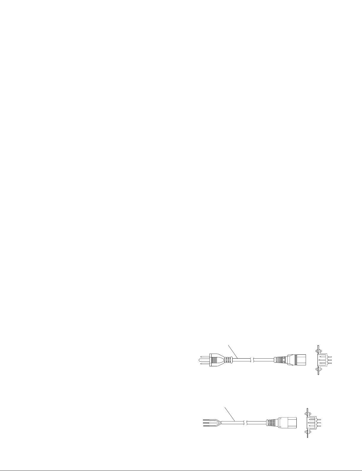
For customers in the U.S.A. and Canada
1 Power cord, 125 V 10 A (2.4 m) : ! 1-551-812-31
AC inlet
1
Installation
1-1. Operating Environment
Operating guaranteed temperature : +5 dC to +40 dC
Performance guaranteed temperature : +10 dC to +35 dC
Operating humidity : 10 % to 90 %
Storage temperature : _20 dC to +60 dC
Mass
MKS-8010A : Approx. 11 kg
Main panel (4ME): Approx. 42 kg
(3ME): Approx. 24 kg
(2ME): Approx. 20 kg
Prohibited locations for installation
. Areas where the unit will be exposed do direct sunlight
or any other strong lights.
. Dusty areas
. Areas subject to vibration.
. Areas with strong electric or magnetic fields.
. Areas near heat sources.
. Areas where is subject to electrical noise.
. Areas subject to static electricity.
Ventilation
The inside of the MKS-8010A is cooled by a fan (side on
the rear).
The power supply can be damaged if the exhaust vent (side
on the rear) and air intake (front panel) are blocked or the
fan is stopped.
For the MKS-8010A, leave a blank space of more than 10
cm in the front and back sides, and more than 5 cm in the
right and left sides.
n
As the inrush current flows at turn-on, the capacity of the
AC power source must be commensurate with this load.
If the capacity of the AC power is not adequately large, the
AC power source breaker will operate or the unit will
abnormally operate.
Inrush current
MKS-8010A: Maximum 14 A (at 100 V)/64 A (at 240 V)
2. Recommended power cord
This unit does not come with a power cord.
To get a power cord, please contact your local Sony Sales
Office/Service Center.
w
. Use the approved Power Cord (3-core mains lead)/
Appliance Connector/Plug with earthing-contacts that
conforms to the safety regulations of each country if
applicable.
. Use the Power Cord (3-core mains lead)/Appliance
Connector/Plug conforming to the proper ratings (Voltage, Ampere).
If you have questions on the use of the above Power Cord/
Appliance Connector/Plug, please contact your local Sony
Sales Office/Service Center.
w
. Never use an injured power cord.
. Plugging the power cord in the AC inlet, push as far as it
will go.
1-2. Power Supply
1. Power specifications
A switching regulator is used for the power supply of
MKS-8010A. A voltage within the range of 100 V to 240
V can be used without changing the supply voltage.
Power requirements: AC 100 to 240 V ± 10 %
Power frequency: 50/60 Hz
Current consumption: MKS-8010A: Maximum 3.0 A
CCP-8000 IM
For customers in the all European countries
1 Power cord, 250 V 10 A (2.5 m) : ! 1-782-929-12
1
AC inlet
1-1

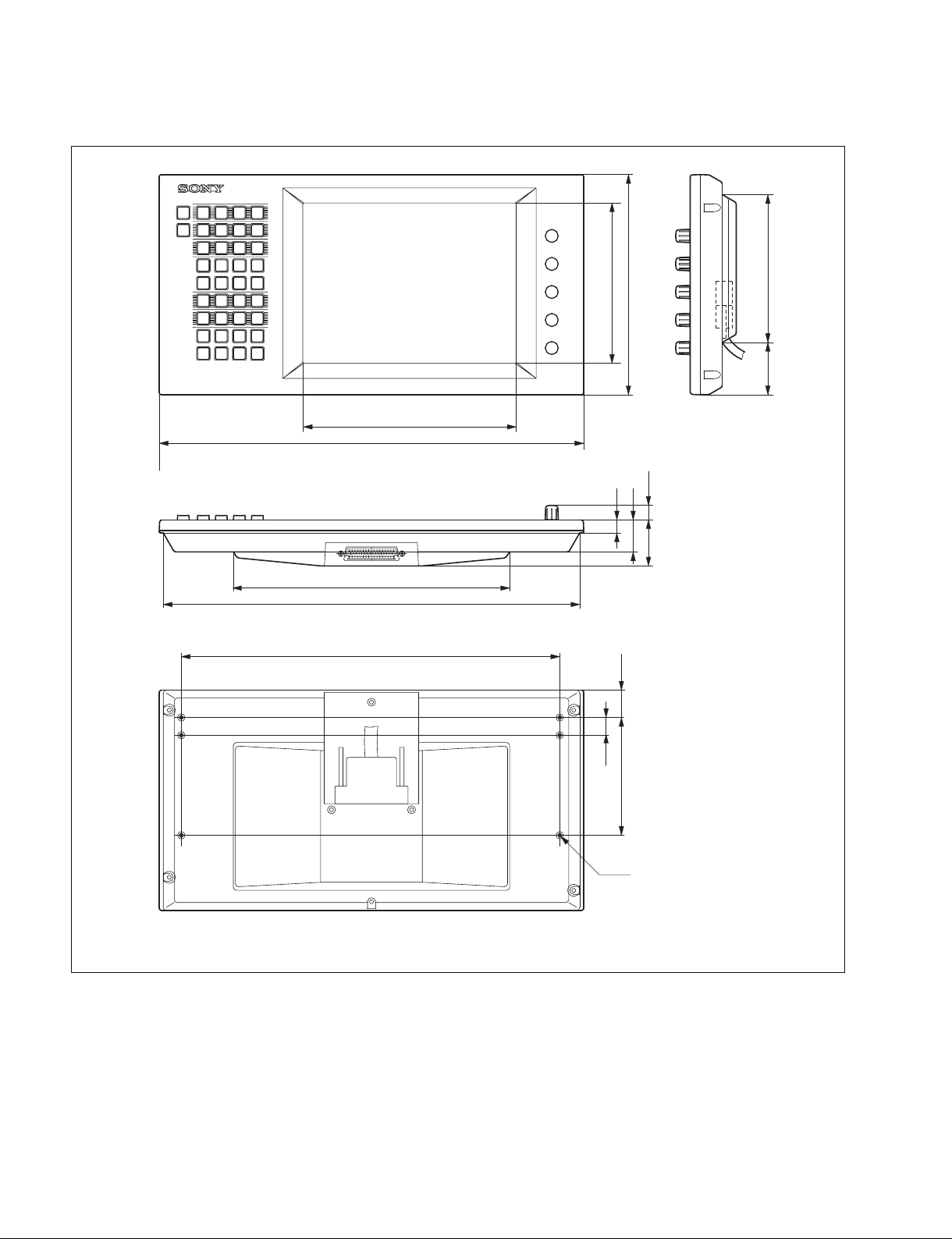
1-3. Installation Space
1-3-1. External Dimensions
System control unit MKS-8010A
520
390
ø26
7
43.6
440
372
482
63.1
52.2
Unit : mm
1-2
CCP-8000 IM

Main panel/AUX panel/Menu panel MKS-8011A
46
424
213
220
160
132
528
KF
TO
KF
+/-
CLR
EFF
GPI
AUTO
TRANS
SHOT
SNAP
XPT
XPT
XPT
M/E3M/E
M/E
M/E
M/E
UNDO
RATE
MCRO
BOX
SHOT
EFF
FTB
DSK1 DSK2 DSK3 DSK4
BKGD
DSK3
KEY3
KEY3
HOLD
HOLD
HOLD
3
1
1
1
SHIFT
SHIFT
SHIFT
DISS
TRANS
9
654
87
STORE
STATSTCSTORE
RTR
P/P
P/P
ALL P-BUS GPI
23
234
M/E M/E
USER USER USER
MASTR
1
1
M/E
USER
32
M/E
M/E
1
M/E
AUTO
K-SS
K-SS
STORE
K-TR
ENBL
ENBL
K-MOD
DMEWIPEMIX
DSK1 DSK2 DSK3 DSK4
MIX
DME
SUPER
MIX NAM
PST
MIX
COLOR
KEY
ALL WIPE
PRIOR
DSK4
ASGN
MCRO
KEY4
ASGN
MCRO
KEY4
ASGN
MCRO
XPT
XPT
XPT
HOLD
HOLD
HOLD
ENBL
MCRO
ENBL
MCRO
ENBL
MCRO
32
32
M/EM/E32M/EM/E
M/EM/E32M/EM/E
2
M/E2M/E
1
1
1
M/E
M/E
M/E
SHIFT
SHIFT
SHIFT
SHIFT
SHIFT
SHIFT
TRIM
ENBL
321
1
DEV
DME
234
DME DME
1
DME
M/E
2K 3K
M/E
1K
M/E
ONONONON
DSK1 DSK2 DSK3 DSK4
PVW
TRANS
REVNORM
/REV
NORM
SET
PRIOR
RUN
RUN
RUN
AUTO
AUTO
AUTO
XPT
XPT
XPT
HOLD
HOLD
HOLD
3
32
32
M/E3M/E
M/EM/E32M/EM/E
M/EM/E32M/EM/E
2
M/E2M/E
1
1
1
M/E1M/E
M/E1M/E
M/E1M/E
SHIFT
SHIFT
SHIFT
ENTER
0
RCALL
6782
DME DME DME DEV
5
DME
DMEKP/PPST
V
DME
K
P/P
AUTO
TRANS
AUTO
TRANS
AUTO
TRANS
AUTO
TRANS
KF
SET
LIMIT
PTN
LIMIT
CUT
AUTO
TRANS
UTIL
UTIL
UTIL
XPT
XPT
XPT
HOLD
HOLD
HOLD
SHIFT
SHIFT
SHIFT
1443
FROM
NEXT
PAUSE
GO TO
KF
KF
LOOP
PREV
GO TO
TURN
LOC
LOC
ASP
AXIS
SHOT
ONONONON
KEY1 KEY2 KEY3 KEY4
PVW
TRANS
REVNORM
/REV
NORM
SET
PRIOR
RUN
AUTO
XPT
HOLD
32
M/EM/E32M/EM/E
1
M/E1M/E
SHIFT
OVER
PASTE
EFF
DUR
DUR TC
CONST
DEL MOD UNDO
COPY ALL
KF
DUR
EDIT
ENBL
SHIFT INS
DELAY
Z
ROT
Y CTR
XYZ
X
SIZE
CLR
BUFR
SKEW
PERS
KF
FF
STOP
NEXT
RE
RUN
LOC
SHIFT WORK
SEL
BANK1BANK0BANK
BOX
MCRO
AUTO
TRANS
AUTO
TRANS
AUTO
TRANS
AUTO
TRANS
KF
SET
LIMIT
PTN
LIMIT
CUT
AUTO
TRANS
UTIL
XPT
HOLD
SHIFT
WIND
EFF
NORM REV
NORM
/REV
LOOP
ONONONON
K-SS
K-SS
AUTO
STORE
TRANS
K-TR
ENBL
ENBL
K-MOD
AUTO
TRANS
DMEWIPEMIX
AUTO
TRANS
KEY1 KEY2 KEY3 KEY4
KEY1 KEY2 KEY3 KEY4
AUTO
TRANS
KF
SET
LIMIT
PTN
LIMIT
PVW
CUT
TRANS
MIX
DME
SUPER
REVNORM
AUTO
TRANS
/REV
NORM
MIX NAM
PST
MIX
COLOR
KEY1 KEY2 KEY3 KEY4
KEY
ALL WIPE
SET
BKGD
PRIOR
PRIOR
SEL
BANK1BANK0BANK
UNDOWIPE
RATE
STATS
STORE
TRANS
DME
EFF
BOX
SNAP
SHOT
SHOT
MCRO
RUN
KEY3
KEY4
UTIL
AUTO
ASGN
MCRO
XPT
XPT
XPT
XPT
HOLD
HOLD
ENBL
MCRO
HOLD
HOLD
32
32
M/EM/E32M/EM/E
M/EM/E32M/EM/E
1
1
1
M/E
M/E
M/E1M/E
SHIFT
SHIFT
SHIFT
SHIFT
SHIFT
432
8765
FM
DMEDMEDME
FEED
DELEG
MON
KEY
PROC
1
DME
PTNCVKCRKLUM
TRANSKEY4KEY3KEY2
P/P
3
M/E
2
LIN
M/E
1
M/E
KEY1
K-SS
K-SS
K-TR
ENBL
K-MOD
KEY1 KEY2 KEY3 KEY4
MIX
SUPER
MIX NAM
KEY1 KEY2 KEY3 KEY4
KEY
BKGD
PRIOR
UNDOWIPE
RATE
STATS
STORE
TRANS
DME
SNAP
SHOT
KEY3
KEY4
ASGN
MCRO
XPT
XPT
HOLD
HOLD
ENBL
MCRO
32
M/EM/E32M/EM/E
1
1
M/E
M/E
SHIFT
SHIFT
SHIFT
DEV
DME DME DME DME
RIDE
OVER
EDGE
SOFT
EMBOS
KEY
OUT
DROP
SHDW
FILL
MATTE
BDR
DROP
SPLIT
BDR
SEL
AUTO
ONONONON
STORE
ENBL
DMEWIPEMIX
KEY1 KEY2 KEY3 KEY4
PVW
TRANS
DME
REVNORM
/REV
NORM
PST
MIX
COLOR
ALL WIPE
SET
PRIOR
EFF
SHOT
RUN
AUTO
XPT
HOLD
32
M/EM/E32M/EM/E
1
M/E1M/E
SHIFT
RUN
MORE
USER
CTRL
8
4
DME
DME
P/P
SRC TRGT
P/P
LINE
ZABTN TRACE
SUB
DME
DME
MASK
MASK
MAIN AUTO
KEY
SHOW
AUTO
TRANS
AUTO
TRANS
AUTO
TRANS
AUTO
TRANS
LIMIT
PTN
CUT
AUTO
TRANS
SEL
BANK1BANK0BANK
BOX
MCRO
UTIL
XPT
HOLD
SHIFT
GLB
67
23
DME
DME
M/E M/E
LOCAL
123
5
M/E1DME
DME
MENU
UNDOWIPE
RATE
STATS
STORE
TRANS
DME
EFF
SNAP
SHOT
KF
SET
K-SS
K-SS
STORE
LIMIT
K-TR
ENBL
ENBL
K-MOD
DMEWIPEMIX
KEY1 KEY2 KEY3 KEY4
MIX
DME
SUPER
MIX NAM
PST
MIX
COLOR
KEY1 KEY2 KEY3 KEY4
KEY
ALL WIPE
BKGD
PRIOR
KEY3
KEY4
ASGN
MCRO
XPT
XPT
HOLD
HOLD
ENBL
MCRO
32
M/EM/E32M/EM/E
1
1
M/E
M/E
SHIFT
SHIFT
SHIFT
69.569.5
1304
1407
782
80
57
652
BLACK
BLACK
BLACK
BLACK
BLACK
BLACK
BLACK
BLACK
BLACK
BLACK
BLACK
BLACK
BLACK
BLACK
BLACK
BLACK
BLACK
73
4873
9.5
72
300
BLACK
BLACK
BLACK
BLACK
BLACK
BLACK
BLACK
49 59.7
59
98
104
Unit : mm
CCP-8000 IM
1-3
Menu panel MKS-8011A detailed dimensions
276
416
378
213
424
160
13
220
27.3
32
147.8
52.3
14.5
46
1-4
17.7
117.7
6-M3
Unit : mm
CCP-8000 IM
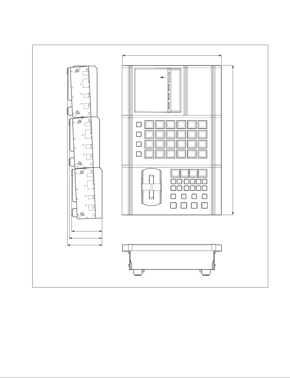
Extension adaptor MKS-8075A/Memory card/USB adaptor MKS-8076
BANK
1
BANK
2
BANK
3
BANK
4
DSK3
DSK4
DSK3
ONONON
DSK2
ON
DSK1
DSK1
DSK4
DSK2
K-SS
STORE
TAKE TAKE TAKE TAKE
WIPE
MIX
DME
CUT
K-SS
SHIFT
UNDO
263
396
79
85
91
Unit : mm
CCP-8000 IM
1-5
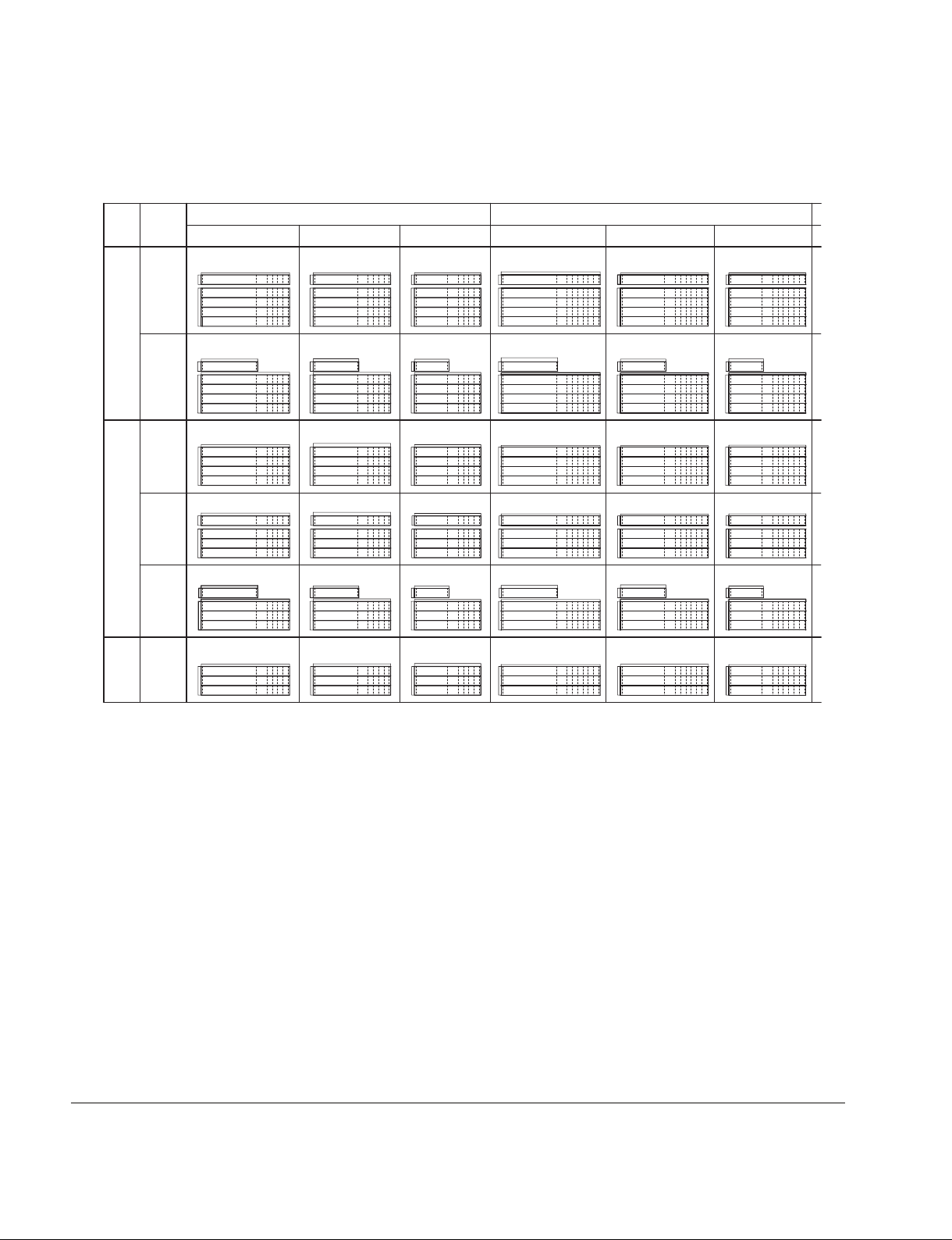
1-3-2. Main Panel/AUX Panel Configuration List
ME
4ME
3ME
2ME
AUX
SEPARATE
FULL
SEPARATE
ONLY
BUILT
-IN
SEPARATE
FULL
SEPARATE
ONLY
BUILT
-IN
NARROW MEDIUM
32XPT 24XPT 16XPT 24XPT32XPT 16XPT
432NF ASSY 424NF ASSY
1223
528 132
782
132
528
528
332NF ASSY 316NF ASSY
396 132
332NO ASSY 324NO ASSY
132
396
232NB ASSY 224NB ASSY
396
1223
1223
1223
782
1223
1223
1071
132
528
424NO ASSY432NO ASSY
630
132
528
324NB ASSY332NB ASSY
1071
528
324NF ASSY
1071
132
396
630
132
396
1071
396
1071
1071
416NF ASSY
919
132
528
416NO ASSY
478
132
528
528
396
132
396
396
919
316NB ASSY
919
919
132
316NO ASSY
478
919
216NB ASSY
919
1369.7
132
528
782
132
528
528
132
396
132
396
396
1369.7
332MB ASSY
1369.7
332MF ASSY
1369.7
332MO ASSY
782
1369.7
232MB ASSY 224MB ASSY
1369.7
424MF ASSY432MF ASSY
132
528
424MO ASSY432MO ASSY
630
132
528
324MB ASSY
528
324MF ASSY
132
396
324MO ASSY
630
132
396
396
1217.7
1217.7
1217.7
1217.7
1217.7
1217.7
416MF ASSY
1065.7
132
528
416MO ASSY
478
1065.7
132
528
316MB ASSY
1065.7
528
316MF ASSY
1065.7
132
396
316MO ASSY
478
1065.7
132
396
216MB ASSY
1065.7
396
NARROW: Configuration that a module having width of 220 mm such as 10 Key Pad Module MKS-8026A is installed outside of the panel
with the use of the Extension Adaptor MKS-8075A.
MEDIUM: Configuration that the Compact Transition Module MKS-8027A / 8028A is going to be used.
STANDARD: Configuration that a module having width of 220 mm such as 10 Key Pad Module MKS-8026A is installed inside the panel.
WIDE: Configuration that the Simple Transition Compact Module MKS-8021ASC / 8022ASC is going to be used.
1-6
CCP-8000 IM

132
1443
STANDARD
24XPT32XPT 16XPT
424TF ASSY432TF ASSY
1291
132
416TF ASSY
1139
132
WIDE
32XPT 16XPT24XPT
432WF ASSY 424WF ASSY
1516.3
132
132
1364.3
416WF ASSY
1212.3
132
528
782
132
332TB ASSY
528 528
332TF ASSY
132
396
332TO ASSY
782
132
396
232TB ASSY 224TB ASSY
396
1443
1443
1443
1443
1443
528
424TO ASSY432TO ASSY
630
132
528
324TB ASSY
528
324TF ASSY
132
396
324TO ASSY
630
132
396
396
1291
1291
1291
1291
1291
528
416TO ASSY
478
132
528
316TB ASSY
1139
528
316TF ASSY
1139
132
396
316TO ASSY
478
132
396
216TB ASSY
1139
396
1139
1139
528
432WO ASSY 424WO ASSY
782
132
528
332WB ASSY
528
332WF ASSY
132
396
332WO ASSY
132
396
396
1516.3
1516.3
1516.3
782
1516.3
1516.3
528
630
132
528
324WB ASSY
528
324WF ASSY
132
396
324WO ASSY
630
132
396
224WB ASSY232WB ASSY
396
1364.3
1364.3
1364.3
1364.3
1364.3
528
416WO ASSY
478
132
528
316WB ASSY
1212.3
528
316WF ASSY
1212.3
132
396
316WO ASSY
478
132
396
216WB ASSY
1212.3
396
Unit : mm
1212.3
1212.3
CCP-8000 IM
1-7
Loading...