


3-863-129-11 (1)
Camera Control Unit
Operating Instructions
Before operating the unit, please read this manual thoroughly and retain it for future reference.
CCU-TX50/50P
© 2004 Sony Corporation

WARNING
To prevent fire or shock hazard, do not expose the unit to rain or moisture.
To avoid electrical shock, do not open the cabinet. Refer servicing to qualified personnel only.
THIS APPARATUS MUST BE EARTHED.
This symbol is intended to alert the user to the presence of important operating and maintenance (servicing) instructions in the literature accompanying the appliance.
For the customers in the USA (for CCU-TX50)
This equipment has been tested and found to comply with the limits for a Class A digital device, pursuant to Part 15 of the FCC Rules. These limits are designed to provide reasonable protection against harmful interference when the equipment is operated in a commercial environment. This equipment generates, uses, and can radiate radio frequency energy and, if not installed and used in accordance with the instruction manual, may cause harmful interference to radio communications. Operation of this equipment in a residential area is likely to cause harmful interference in which case the user will be required to correct the interference at his own expense.
You are cautioned that any changes or modifications not expressly approved in this manual could void your authority to operate this equipment.
The shielded interface cable recommended in this manual must be used with this equipment in order to comply with the limits for a digital device pursuant to Subpart B of Part 15 of FCC Rules.
WARNING: THIS WARNING IS APPLICABLE FOR USA ONLY.
Using this unit at a voltage other than 120V may require the use of a different line cord or attachment plug, or both. To reduce the risk of fire or electric shock, refer servicing to qualified service personnel.
For the customers in Europe (for CCU-TX50P)
This product with the CE marking complies with both the EMC Directive (89/336/EEC) and the Low Voltage Directive (73/23/EEC) issued by the Commission of the European Community.
Compliance with these directives implies conformity to the following European standards:
•EN60950: Product Safety
•EN55103-1: Electromagnetic Interference (Emission)
•EN55103-2: Electromagnetic Susceptibility (Immunity)
This product is intended for use in the following Electromagnetic Environment (s):
E1 (residential), E2 (commercial and light industrial),
E3 (urban outdoors) and E4 (controlled EMC environment, ex. TV studio).
2

Table of Contents |
|
Overview ................................................................. |
4 |
Function and Location of Parts and Controls .... 5 |
|
Front panel .......................................................... |
5 |
Rear panel ........................................................... |
9 |
Connecting the CCU-TX50/50P to the Video |
|
Camera ................................................................. |
12 |
Notes on connections ....................................... |
12 |
Self-Diagnostics .................................................... |
13 |
Entering the Self-diagnostics Mode ................. |
13 |
Settings of the Camera ..................................... |
13 |
Status Display of the Unit ................................ |
13 |
Self-diagnostics of the Camera System ............ |
14 |
Results of the Self-diagnosis of the Internal |
|
Boards of the Unit .......................................... |
14 |
Diagnostics Page of the Camera ....................... |
16 |
Exiting the Self-diagnostic Mode ..................... |
16 |
When an Error Occurs ...................................... |
16 |
Notes on Use ......................................................... |
17 |
Specifications ........................................................ |
17 |
General ............................................................. |
17 |
Input signals ..................................................... |
17 |
Output signals ................................................... |
17 |
Camera input/output signals ............................. |
18 |
Supplied accessories ......................................... |
18 |
Optional accessories ......................................... |
18 |
3

Overview
The CCU-TX50/50P is a camera control unit that connects to DXC-D50 Series Color Video Cameras via the CA-TX50/50P Camera Adaptor.
Features of this unit are described below.
Full-featured signal transfer functions
•The CCU-TX50/50P is able to transfer wide band component video signals.
•The maximum triaxial cable length that can be used to
connect this unit to a camera adaptor is max. 750 m (when using a Belden φ8.5 mm cable) or 1125 m (when using a Belden φ13.2 mm cable).
•Transfer functions are provided for the following signals.
Return video, teleprompter signal, microphone audio, program audio, red tally and green tally signals
•An intercom system is also provided.
Flexibly adaptable camera control functions
•The camera control panel mounted on the front panel of the unit enables video camera operations to be controlled from the unit.
•When the RCP-D50 remote control panel is connected to the rear panel of the unit, the video camera operation can be controlled from both the remote control panel and the front panel of the unit.
Wide array of input/output signals
The input and output connectors provided for the CCUTX50/50P include those for outputting such signals as a composite video signal (VBS), component video signals (switchable to RGB), SDI signals, and video signals for video and waveform monitors, for inputting a reference signal for external synchronization.
Status and self-diagnostics display on the picture monitor
You can check all sorts of settings of the unit and the results of self-diagnoses of internal boards on the monitor connected to the PIX connector on the rear panel.
Rack mountable
Two CCU-TX50/50P units can be installed side by side in the optional RMM-301 Rack Mount Bracket.
4 Overview
Function and Location of Parts and Controls
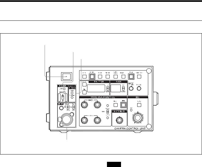
Front panel
a Camera number sheet/tally indicator
b POWER switch/CAM and MAIN indicators c CABLE ALARM indicators
d INCOM input/output/setting section
a Camera number sheet/tally indicator
Lights red when the red tally signal is input (e.g. when the video signal from the video camera connected to the CCU-TX50/50P goes on air). When the CALL button on the unit or RCP-D50 remote control panel is pressed, the indicator lights red if it is not lit, and goes off if it is lit.
The indicator lights green when the green tally signal is input.
Attach the supplied number sheet here to indicate the camera number.
bPOWER switch/CAM (camera) and MAIN indicators
The POWER switch turns on or off the power supply to the entire camera system, including the CCU-TX50/ 50P, the video camera, and the remote control unit connected to the REMOTE connector on the CCUTX50/50P.
The MAIN and CAM indicators light when the POWER switch is turned on.
The CAM indicator goes off when the power is turned off by the CAM PW button on the remote control panel.
Note
If the fan in the CCU-TX50/50P stops, the MAIN indicator will flash simultaneously to warn you of the abnormal condition. If this occurs, turn the POWER switch off immediately and contact Sony service personnel.
c CABLE ALARM indicators
OPEN: Lights when no triaxial cable is connected to the CAMERA connector on the rear panel of the CCU-TX50/50P, or when the load current is extremely low even when a camera cable is connected. SHORT: Lights when there is a current overflow in the triaxial cable.
d INCOM (intercom) input/output/setting section
INCOM (intercom) connector (XLR, 5-pin)
Connects a headset.
INCOM level control
Adjusts the input level of the headset.
MIC/PGM (program audio) switch
ON: Turns on the headset microphone.
Function and Location of Parts and Controls |
5 |
|
|

OFF: Turns off the headset microphone.
PGM: Outputs the program audio. When this position is selected, the INCOM level control adjusts input level of the program audio.
INCOM selector
Selects the pathway of intercom signals output/input through the INCOM connector.
PROD: Producer line.
PRIV: Producer line and engineer line are cut off and communication is possible only between the CCUTX50/50P and the camera connected to the rear panel of the CCU-TX50/50P.
ENG: Engineer line.
e CALL button
f PANEL button
g BARS button
h5600K button
i AUTO KNEE button
j SKIN DTL button
k TLCS button
l CHARACTER button
m MASTER GAMMA adjustment knob
n DETAIL adjustment knob
e CALL button
When you press this button, the TALLY indicator on the camera adaptor lights. The tally indicator on the unit also lights red when you press this button, and goes off if the CALL button is pressed while it is lit.
f PANEL button
When the RCP-D50 camera control panel is connected, press this button to light it up so you can select the device which controls the camera.
The unit can control the camera when this button is lit.
gBARS button
Press this button (which lights up when pressed) to send the color bar signal to the monitor. The color bars then appear on the monitor.
h 5600K button
Press this button (which lights up when pressed) to convert the color temperature electronically instead of using the optical filter.
i AUTO KNEE button
Press this button (which lights up when pressed) to activate the automatic knee function which optimizes the input signal compensation.
j SKIN DTL button
Use this button to turn the skin detail correction function on or off. Press this button (which lights up when pressed) to set the skin detail correction function to on. To set this function to off, press this button again.
k TLCS (total level control system) button
Press this button to turn the total level control system on or off. When this button is lit, it is turned on, and settings
6 Function and Location of Parts and Controls
 Loading...