


 Loading...
SONOLINE G20 Ultrasound Imaging System [2] Instructions for Use
|
|
|
|
Siemens Medical Solutions USA, Inc. |
|
|
|
|
|
|
|
10031089-ABS-002-01 |
|||

SONOLINE G20
Ultrasound Imaging System [2] Instructions for Use
Software Versions 1 and 2
Siemens Medical Solutions USA, Inc.
Ultrasound Division
1230 Shorebird Way
Mountain View, CA 94043-1344
U.S.A.
(800) 498-7948
(650) 969-9112
CE Declaration
This product is provided with a CE marking in accordance with the regulations stated in Council Directive 93/42/EEC of June 14, 1993 concerning Medical Devices. Siemens Medical Solutions USA, Inc., is certified by Notified Body 0123 to Annex II.3 – Full Quality System.
Authorized EC Representative:
Siemens Aktiengesellschaft
Medical Solutions
Henkestraße 127
D-91052 Erlangen
Germany
©2004-2005 Siemens Medical Solutions USA, Inc.
All Rights Reserved.
February 2005
Manuals distributed from the Federal Republic of Germany or Japan are printed in the Federal Republic of Germany.
Manuals distributed from the United States of America are printed in the United States of America.
SONOLINE G20, ReadySet, TGO, THI, MultiHertz, DIMAQ, microCase, SynAps, QuickSet, SuppleFlex, and Evolve Package are trademarks of Siemens Medical Solutions USA, Inc.
Windows, CIDEX, CIDEX Plus, CIDEX OPA, Milton, Virkon, and Gigasept FF are registered trademarks of their respective owners.
Siemens reserves the right to change system specifications at any time.
[ 2 ] I N S T R U C T I O N S F O R U S E
i

About This Manual
The Instructions for Use consists of two volumes:
[1] Instructions for Use
The [1] Instructions for Use includes both a general overview and a technical description of the ultrasound imaging system. This manual contains detailed information on the safety and care of the ultrasound system and its transducers. A chapter is dedicated to the description of all system controls. The [1] Instructions for Use also includes the procedures for system setup and beginning an exam.
[2] Instructions for Use
The [2] Instructions for Use includes procedures for acquiring and optimizing images. This manual provides procedures for general and exam-specific measurements and calculations.
The System Reference provides reference information for the ultrasound imaging system.
ii
[ 2 ] I N S T R U C T I O N S F O R U S E

Conventions
Conventions used throughout this manual are listed below. Take a moment to familiarize yourself with these conventions.
Cross-References
This manual provides you information by topic. When additional information exists within this or other manuals, a reference graphic and the name of the book is provided in the right column. If the information exists within the chapter, a cross-reference to the page number is listed. Otherwise, information is referenced by chapter number.
[1] Instructions for Use
Screen Saver |
Ch 1 |
Intended Use |
Ch 1 |
[2] Instructions for Use
Imaging Functions Ch A1
System Presets
You can use the options and settings available in the system presets menu to set up the ultrasound system with your preferences. Presets define the configuration of the system software whenever you power on the system.
A complete listing of system presets is located in the System Reference. Whenever a system preset is discussed in other chapters or in the User and Reference Manuals, a graphic is provided in the right column.
The graphic identifies a preset option or setting in the system presets menu that is available for you to customize your ultrasound system. The name of the category on the menu containing the system preset is listed for
your convenience.
System Reference
Accessories |
|
and Options |
Ch 2 |
F6
Default Settings
►Automatic Freeze
Response
[ 2 ] I N S T R U C T I O N S F O R U S E
iii

Warnings, Cautions, and Notes
WARNING: Warnings are intended to alert you to the importance of following the correct operating procedures where risk of injury to the patient or system user exists.
Caution: Cautions are intended to alert you to the importance of following correct operating procedures to prevent the risk of damage to the system.
Note: Notes contain information concerning the proper use of the system and/or correct execution of a procedure.
Control Panel Keys, Controls, and Menu Selections
Keys and controls located on the control panel are identified by uppercase, boldface type.
Example: Rotate the DEPTH/ZOOM control.
Function keys located on the keyboard are identified by the number of the function key.
Example: Press the F6 key.
Menu selections are indicated with the name of the selection in boldface type.
Example: Select Next to access the second page of on-screen menu selections.
iv
[ 2 ] I N S T R U C T I O N S F O R U S E

Selection of On-Screen Objects
The SET key on the control panel functions as a point-and-select device (similar to a computer mouse) when used with the trackball. To select an on-screen object such as a button or a X symbol, roll the trackball to position the pointer (cursor) on the object and then press the SET key on the control panel.
In this manual, the term "select" or "click" describe the trackball and SET key action required to select an on-screen object. In the example below, phrases A, B, C, and D are equivalent actions.
A.Roll the trackball to the Search button and then press the SET key.
B.Select the Search button.
C.Click the Search button.
D.Click Search.
Special Terms and Menu Options
Special terms are indicated in boldface italics and are accompanied by a brief description on their first use in the manual.
Example: Provides on-screen anatomical graphics of pictograms that indicate the anatomy under evaluation.
Within a procedure, options in the system presets are identified in text as boldface type.
Example: Highlight the Keyboard – Annotation option.
[ 2 ] I N S T R U C T I O N S F O R U S E
v

Table of Contents
[2] Instructions for Use
Chapter Title |
Chapter Description |
|
|
Chapter A1 |
Procedures for general imaging functions, including Annotations and how |
Imaging Functions |
to create QuickSets™. |
Chapter A2 |
Description of the imaging functions for 2D-mode and M-mode imaging. |
2D-Mode and M-Mode |
Includes an explanation of the Ensemble™ Tissue Harmonic Imaging |
Imaging Functions |
option. |
Chapter A3 |
Information on how to review CINE data, either frame by frame or as a |
CINE |
continuous display. |
Chapter A4 |
Description of the biopsy (puncture) guidelines on the ultrasound system, |
Biopsy |
including the needle path verification procedure. |
Chapter B1 |
Step-by-step procedures for using the Measurement function. The |
Measurements |
procedures that apply to all exam types, including the report feature, are |
and Calculations |
described first. |
Chapter B2 |
Description of the features and calculations specific to the Obstetrical |
Obstetrical Measurements |
package, including fetal cardiac measurements. |
and Calculations |
|
Chapter B3 |
Description of the features and calculations specific to the Emergency |
Emergency Medicine |
Medicine (EM) package, including the report-specific information for: |
Measurements |
FAST (Focused Abdominal Sonography in Trauma) |
|
and Calculations |
||
Aorta |
||
|
||
|
Gallbladder |
|
|
Renal |
|
|
Obstetric |
|
|
Cardiac |
|
|
Bladder |
|
|
DVT (Deep Vein Thrombosis). |
Chapter B4
Urology and Rectal
Measurements
and Calculations
Description of the features and calculations specific to the Urology and Rectal packages.
Chapter B5
Cardiac Measurements
and Calculations
Chapter C1
Transducer Accessories
Chapter C2
Endo-V II Transducer
Chapter C3
Endo-P II Transducer
Description of the features and calculations specific to the Cardiac package. All measurement functions for a Cardiac exam are detailed in this chapter.
Attachment procedures for transducer accessories.
Description of the Endo-V II transducer and the Endo-V II needle guide bracket kit.
Description of the Endo-P II transducer and the Endo-P II needle guide bracket kit.
Note: Not all features and options described in this publication are available to all users. Please check with your Siemens representative to determine the current availability of features and options.
vi
[ 2 ] I N S T R U C T I O N S F O R U S E

A1 Imaging Functions |
|
Annotation .......................................................................................................... |
3 |
Direct Text Entry............................................................................................ |
4 |
Labels for Position and Anatomical Structures .............................................. |
5 |
Directional Arrows ......................................................................................... |
6 |
Pictograms .................................................................................................... |
7 |
QuickSet Feature................................................................................................ |
8 |
Creating a QuickSet....................................................................................... |
8 |
Activating a QuickSet .................................................................................. |
10 |
Saving a QuickSet........................................................................................ |
10 |
2D-Mode and M-Mode QuickSets............................................................... |
11 |
[ 2 ] I N S T R U C T I O N S F O R U S E |
A1 - 1 |

A 1 Imaging Functions
A1 - 2 |
[ 2 ] I N S T R U C T I O N S F O R U S E |

Annotation
You can use four methods to annotate an image. Direct text entry using the keyboard
Predefined labels for positions and anatomical structures Pictograms of anatomical structures
Arrow keys
To remove annotation from the image screen, use the F12 key. You can program the system to automatically delete on-screen annotation each time you use the FREEZE key to unfreeze the image. Use the system presets to specify whether all text or all pictograms are deleted at unfreeze.
The default position for the annotation cursor on the image screen is in the location defined by theF11(Home Set) key.
Once you have annotated an image during a patient examination, the system remembers the last position of the cursor; press the SELECT control to redisplay the annotation cursor.
To reposition an annotation:
1.During the annotation function, roll the trackball to position the cursor on the text, label, or arrow.
2.Press the SET key to select the annotation.
3.Roll the trackball to reposition the annotation and then press the SET key.
To delete a single annotation:
1.During the annotation fuction, roll the trackball to position the cursor on the text, label, or arrow.
2.Press the SET key to select the annotation.
3.Press the F12 key on the keyboard.
To change the font size:
1.During the annotation function, select the menu category at the top of the menu and then select Others.
2.Select Font Size and rotate the SELECT control or press the SET key to display the desired setting.
The system applies the selected setting to direct text entry and annotation labels. The new font size does not affect existing annotations.
3.To exit the menu, press the MENU key or the TEXT key.
To hide text:
Press the F13 key to toggle the display of the text on or off.
A 1 Imaging Functions
System Reference
System Presets |
Ch 3 |
F4
General
►Delete Text
on Unfreeze
General
►Delete Pictogram
on Unfreeze
[ 2 ] I N S T R U C T I O N S F O R U S E |
A1 - 3 |
A 1 Imaging Functions
Direct Text Entry
Use the keyboard to enter text directly onto the image area.
To activate text entry:
1.Press the TEXT key on the control panel.
The system places the text cursor on the image screen.
2.To reposition the text cursor, roll the trackball.
3.Use the keyboard to enter text.
4.To exit the text entry function, press the TEXT key on the control panel. To exit the text entry function and delete all text, press the ESCAPE key on the control panel.
A1 - 4 |
[ 2 ] I N S T R U C T I O N S F O R U S E |

A 1 Imaging Functions
Labels for Position and Anatomical Structures
Each exam type has labels for anatomical structures, imaging views, and body positions that can display as onscreen selections when the exam type is active. The labels are stored in libraries. Use the system presets to customize the text for anatomical structures, for imaging views and for body positions. You can:
Add, replace, or delete onscreen menu labels Change the spelling or abbreviation of the labels
Establish the order in which the labels display in the onscreen menu Reset the library to the original system-defined labels
To annotate using a predefined label:
1.During the annotation function, roll the trackball to position the text cursor at the location for a label to display and then press the MENU key.
2.Select the menu category at the top of the menu and then select
Anatomy or Position.
The system displays the list of labels corresponding to the selected menu category.
3.Select the required label and then press the SET key. The system inserts the label at the cursor's position.
4.For each additional label, reposition the cursor, select another label, and press the SET key.
Note: You can place a combined total of 24 labels and arrows on the image screen.
5.To delete the last label from the screen, press the F12 key on the keyboard. Each press of the F12 key deletes a previous label. To delete all annotations from the screen, press the F14 key.
6.Press the TEXT key on the control panel to exit annotation. Press the ESCAPE key to exit and delete the labels.
System Reference
System Presets |
Ch 3 |
F6
Default Settings
►Text Annotation
►►Anatomy or Position
[ 2 ] I N S T R U C T I O N S F O R U S E |
A1 - 5 |

A 1 Imaging Functions
Directional Arrows
You can place arrows on-screen by first pressing the TEXT key on the control panel or the F9 key on the keyboard.
To place an arrow on the image screen:
1.Press the F9 key.
The system displays an arrow on the image screen.
2.Roll the trackball to position the cursor at the required location for the arrow.
Note: If you are adding an arrow immediately after entering text or a label, roll the trackball away from the text before adding the arrow.
Note: You can place a combined total of 24 labels and arrows on the image screen.
3.To change the direction of the arrow, rotate the SELECT control on the control panel.
4.To change the size of the arrow, select Arrow Size in the Others menu.
Note: If the menu is not displayed, select the menu category at the top of the menu and then select Others.
5.To save changes to the arrow's direction and size, press the SET key.
6.To delete an arrow, press the F12 (Delete Word) key.
7.To exit the arrow function and retain all the arrows and labels, press the F9 key on the keyboard or the TEXT key on the control panel. To exit the arrow function and erase all arrows and labels, press the
ESCAPE key.
A1 - 6 |
[ 2 ] I N S T R U C T I O N S F O R U S E |

Pictograms
Pictograms are graphics that display on-screen to indicate the anatomical structure under evaluation and to indicate the orientation of the transducer to the structure. You can rotate fetal pictograms to indicate the orientation of the fetus in utero.
Use the system presets to assign pictograms to each exam type. When the exam is active, pressing the PICTOGRAM key causes the assigned pictograms to display at the bottom of the image screen. One pictogram can display on an image. In Dual-mode and 4B-mode, you can display one pictogram for each image.
The selected pictogram for an image will display until you press the ESCAPE key, select a new pictogram, or begin a new exam. Use the system presets to automatically remove a pictogram when you unfreeze an image.
To display a pictogram:
1.Press the PICTOGRAM key.
The system displays the available pictograms for the active exam type.
2.To select a pictogram, roll the trackball to outline the pictogram and then press the SET key.
The selected pictogram displays with a transducer orientation indicator in the lower left of the image.
3.Roll the trackball to position the transducer orientation indicator.
a.To rotate the indicator, rotate the SELECT control.
b.To anchor the position of the indicator, press the SELECT control.
4.To rotate a fetal pictogram, press and then rotate the SELECT control.
5.To redisplay the list of pictograms, press the MENU key.
6.To remove a pictogram from the screen, press the ESCAPE key while the trackball is assigned to the pictogram function.
[ 2 ] I N S T R U C T I O N S F O R U S E
A 1 Imaging Functions
System Reference
System Presets |
Ch 3 |
F6
Default Settings
►Pictogram List
General
►Delete Pictogram
on Unfreeze
[1] Instructions for Use
Trackball |
|
assignment |
Ch 3 |
A1 - 7

A 1 Imaging Functions
QuickSet Feature
The QuickSet™ feature allows you to capture an optimized configuration of imaging parameter settings for a specific transducer and exam. The system stores this configuration in a file known as a QuickSet.
When a QuickSet is selected as the current exam type, the system activates the associated transducer and resets all imaging functions according to the stored configuration.
Use the system presets to change the default settings for an existing QuickSet.
Creating a QuickSet
You can have a maximum of 32 QuickSets on the system at one time. If you attempt to create a new QuickSet, or load a saved QuickSet from disk after the maximum of 32 is reached, the system requires you to delete one or more existing QuickSets to accommodate the new ones.
To create a QuickSet:
1.Adjust the image parameter settings as required and then press the F8 function key on the keyboard.
The system displays a screen for saving and deleting QuickSets.
2.Roll the trackball to the QuickSet Name field and then press the SET key.
3.Use the keyboard to enter up to 20 characters for the name of the QuickSet.
4.Save the name by either rolling the trackball to the Save button and pressing the SET key or by pressing the ENTER key on the keyboard.
The system displays the image screen and activates the QuickSet you created.
System Reference
System Presets |
Ch 3 |
F6
QuickSet Parameters
A1 - 8 |
[ 2 ] I N S T R U C T I O N S F O R U S E |

A 1 Imaging Functions
To overwrite an existing QuickSet with the current image parameter settings:
1.Adjust the image parameter settings as required and then press the F8 function key.
The system displays a screen for saving and deleting QuickSets.
2.Roll the trackball to an existing QuickSet and then press the SET key.
3.Roll the trackball to the Save button and then press the SET key.
The system displays a message asking if you want to overwrite the QuickSet.
4.Roll the trackball to the OK button and then press the SET key to assign the new QuickSet configuration to the existing name.
To delete an existing QuickSet:
1.Press the F8 function key.
The system displays a screen for saving and deleting QuickSets.
2.Roll the trackball to an existing QuickSet and then press the SET key on the control panel.
3.Roll the trackball to the Delete button and then press the SET key on the control panel.
The system removes the highlighted name from the list of QuickSets. If you attempt to delete a QuickSet when it is the current exam type, the system displays a message stating that you cannot delete a QuickSet currently loaded on the system.
[ 2 ] I N S T R U C T I O N S F O R U S E |
A1 - 9 |

A 1 Imaging Functions
Activating a QuickSet
A QuickSet is a user-defined variation on a system-defined exam type.
To select a QuickSet exam type:
1.Press the F5 function key to access the Exam & QuickSet List.
2.Roll the trackball to the name of a QuickSet.
3.Press the SET key.
Note: When a QuickSet is selected as the current exam type, the system activates the associated transducer and resets all imaging functions according to the stored configuration.
Saving a QuickSet
You can save a QuickSet to a disk using the Preset/QuickSet utilities.
System Reference
System Presets |
Ch 3 |
Disk Function |
Ch 4 |
Preset/QuickSet |
|
Utility |
Ch 5 |
F6
Customize Keys
A1 - 10 |
[ 2 ] I N S T R U C T I O N S F O R U S E |

A 1 Imaging Functions
2D-Mode and M-Mode QuickSets
A QuickSet includes the following 2D-mode and M-mode parameters:
2D-mode |
M-mode |
|
|
Gain |
Sweep Rate |
Persistence |
Dynamic Range |
Gray Map |
Edge Enhancement |
Dynamic Range |
Reject |
Edge Enhancement |
Gain |
Field of View |
Gray Map |
Transmit Power |
Transmit Power |
Depth (mm) |
|
Line Density |
|
Focal Zones |
|
Initial Frequency (MHz) |
|
Rotate |
|
Flip (L/R) |
|
Reject |
|
Res/Speed |
|
Scan Angle (Endo-V II transducer) |
|
SynAps (Synthetic Aperature) |
|
Frequency |
|
Steer |
|
Focus |
|
THI (Tissue Harmonic Imaging) |
|
settings |
|
|
|
[ 2 ] I N S T R U C T I O N S F O R U S E |
A1 - 11 |

A 1 Imaging Functions
A1 - 12 |
[ 2 ] I N S T R U C T I O N S F O R U S E |

A2 2D-Mode and M-Mode Imaging Functions |
|
Activating 2D-Mode ........................................................................................... |
3 |
Imaging Menu ............................................................................................... |
3 |
2D-Mode Formats ......................................................................................... |
4 |
Mixed-Mode Formats............................................................................. |
4 |
Active Image .......................................................................................... |
4 |
Activating Split Mode .................................................................................... |
5 |
Activating Dual-Mode .................................................................................... |
6 |
Activating 4B-Mode ....................................................................................... |
7 |
Activating A-Mode......................................................................................... |
8 |
Activating M-Mode ........................................................................................ |
9 |
Simultaneous Format ............................................................................. |
9 |
M-Mode Formats ................................................................................... |
9 |
2D/M-Mode Display and Update .......................................................... |
10 |
Changing the M-Mode Sweep ............................................................. |
11 |
2D/M-Mode Example Screen Layout............................................................ |
12 |
Imaging Parameters Legend........................................................................ |
12 |
Imaging Parameters ......................................................................................... |
13 |
Changing a Transducer Frequency .............................................................. |
14 |
Changing the Imaging Depth ....................................................................... |
14 |
Adjusting the Overall System Receiver Gain ............................................... |
15 |
Adjusting the Depth Gain Compensation (DGC).......................................... |
16 |
Changing the Dynamic Range ..................................................................... |
17 |
Adjusting the Focus..................................................................................... |
18 |
Single Focal Zone ................................................................................. |
18 |
Multiple Focal Zones ............................................................................ |
18 |
[ 2 ] I N S T R U C T I O N S F O R U S E |
A2 - 1 |
A2 2D - Mode and M - Mode Imaging Functions
Changing the Line Density........................................................................... |
19 |
Maximizing Resolution and Speed............................................................... |
20 |
Synthetic Aperture....................................................................................... |
20 |
Changing the Persistence............................................................................ |
21 |
Changing the Edge Enhancement ............................................................... |
21 |
Selecting a Gray Map .................................................................................. |
22 |
Modifying a Gray Map .......................................................................... |
22 |
Reject for 2D-Mode and M-Mode ........................................................ |
24 |
Adjusting the Field of View .................................................................. |
24 |
Changing the Image Orientation.................................................................. |
26 |
Horizontal Orientation........................................................................... |
26 |
Vertical Orientation............................................................................... |
27 |
Offsetting the Image ................................................................................... |
28 |
Magnifying the Image.................................................................................. |
29 |
Magnifying Split Images....................................................................... |
30 |
Magnifying a Dual Image...................................................................... |
30 |
Magnifying 2D/M-Mode Images........................................................... |
31 |
Ensemble Tissue Harmonic Imaging .............................................................. |
32 |
Optimizing Contrast Resolution and Brightness Uniformity (TGO) ............ |
33 |
A2 - 2 |
[ 2 ] I N S T R U C T I O N S F O R U S E |

A2 2D - Mode and M - Mode Imaging Functions
Activating 2D-Mode
2D-mode is the default imaging mode for the ultrasound system. 2D indicates two-dimensional (2D) grayscale imaging. When you first power on the system, 2D-mode is active.
To access 2D-mode from another imaging mode:
Press the 2D control on the control panel.
The system displays in 2D-mode (full screen).
Note: When operating in mixed modes (for example, 2D-mode with M-mode), pressing the 2D control deactivates M-mode and displays full-screen 2D-mode imaging.
Imaging Menu
During 2D-mode or M-mode imaging, you can use selections in the Imaging menu to adjust the settings for imaging parameters.
To display the 2D-mode Imaging menu:
1.Press the MENU key on the control panel.
The system displays the default menu or the menu last viewed.
2.To change the displayed menu, roll the trackball to highlight the menu category at the top of the menu on the left of the screen.
Example: M X.
The system displays the list of available menu categories. If the image is live, the CINE menu is not available.
3.Roll the trackball to 2D and then press the SET key. The system displays the 2D-mode menu.
4.Adjust imaging parameters using selections in the menu using the trackball with the SELECT control or SET key located on the control panel.
5.Continue adjusting imaging parameters and then press the MENU key to exit the menu.
[ 2 ] I N S T R U C T I O N S F O R U S E |
A2 - 3 |
A2 2D - Mode and M - Mode Imaging Functions
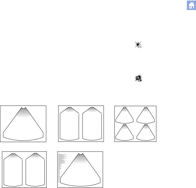
2D-Mode Formats
You can display 2D-mode images in different formats: Split, Dual and 4B modes. Imaging capability in 2D-mode, M-mode, A-mode, and mixed
modes is available. Active image indicator.
Mixed-Mode Formats
2D/M-mode
Active Image
In Split, Dual, and 4B modes, while more than one 2D-mode image displays on the monitor, you can adjust imaging parameters for one image at a time. This image is the active image. The system indicates the active image with the active image indicator.
Inactive image indicator.
Standard 2D-mode.
Split (B+B) mode.
Dual-mode.
2D-mode with A-mode. |
4B-mode. |
A2 - 4 |
[ 2 ] I N S T R U C T I O N S F O R U S E |

A2 2D - Mode and M - Mode Imaging Functions
Activating Split Mode
Split mode creates side-by-side images from one 2D-mode image. The two images are simultaneously frozen or real-time. Split mode is available with all transducers.
When you first initiate Split mode, the image parameter settings from the previous mode are applied to both images. Certain imaging parameters (such as Gray Map, A-mode, Reject, and Modify Map) can be changed in the right image, allowing comparison of the effects of different image settings on an anatomical structure.
To activate Split mode:
1.From a 2D-mode image display, press the SPLIT key on the control panel.
The left image is the reference image.
2.To display the full-screen 2D-mode image, press the SPLIT key or the 2D control on the control panel.
3.To simultaneously freeze both images, press the FREEZE key on the control panel.
4.To exit Split mode, press the 2D control.
[2] Instructions for Use
Imaging
Parameters A2-13
[ 2 ] I N S T R U C T I O N S F O R U S E |
A2 - 5 |

A2 2D - Mode and M - Mode Imaging Functions
Activating Dual-Mode
In Dual-mode, two acquired 2D-mode images display side-by-side on the image screen. Both images are obtained separately, and only one image displays in real-time.
When you first activate Dual-mode, the imaging settings from the previous mode are applied to the first image. The second image retains the same settings as the first image.
You cannot activate M-mode while Dual-mode is active. You cannot activate Dual-mode while 2D/M-mode is active.
To activate Dual-mode:
1.Press the left DUAL/SELECT key on the control panel to display an image on the left side of the screen, or press the right key to display an image on the right side of the screen.
Only one image can be active at a time. The active image is indicated by the lighting intensity of the selected key and by the active
image indicator.
2.To generate a second image, press the other DUAL/SELECT key. The system freezes the active image and activates a second image.
3.To display a full screen image, press the key for the active image a second time. Press the key again to restore the side-by-side display.
4.To inactivate the current image and activate the other image in a side-by-side display, press the DUAL/SELECT key.
The system shifts the active image indicator to the selected image and freezes both images.
5.Press the FREEZE key to unfreeze the Dual-mode display.
6.To exit Dual-mode, press the 2D control on the control panel.
[2] Instructions for Use
Imaging
Parameters A2-13
A2 - 6 |
[ 2 ] I N S T R U C T I O N S F O R U S E |

A2 2D - Mode and M - Mode Imaging Functions
Activating 4B-Mode
In 4B-mode, four separately acquired 2D-mode images display on the image screen. Only one image can display in real-time.
When you first activate 4B-mode, the imaging settings from the previous mode are applied to the first image. Subsequent images retain the same settings as the previous image.
To activate 4B-mode:
1.From a 2D-mode display, press the 4B key on the control panel.
The first image displays in the upper left quadrant of the screen. This is the active image, as identified by the brightened active image indicator.
2.Press the FREEZE key.
The image is frozen in position and a second image displays in the next available quadrant.
3.To continue to place images, press the FREEZE key.
4.To cycle through the images, first freeze the active image and then press the 4B key. To display the active image in real-time, unfreeze the system.
5.To exit 4B-mode, press the 2D control.
[ 2 ] I N S T R U C T I O N S F O R U S E |
A2 - 7 |

A2 2D - Mode and M - Mode Imaging Functions
Activating A-Mode
Important: At the time of publication, A-mode was not cleared for use by the U.S. Food and Drug Administration. Before using A-mode, check the current regulations for the country in which you are using this system to determine if A-mode is cleared for use.
A-mode is available in 2D-mode. A-mode displays in real-time or displays on a frozen image.
Once activated, A-mode displays even when you change modes. If you enter into a mode that does not support A-mode, the A-mode display is removed. When you activate a mode that does support A-mode, the display and cursor return.
To display A-mode:
1.Press the MENU key on the control panel to display the 2D-mode Imaging menu when 2D-mode is active.
2.Roll the trackball to A-mode on the 2D-mode menu and press the SET key to toggle the setting to On.
The system places an A-mode cursor in the image. The location of the cursor designates the region of sampling.
3.Roll the trackball to position the cursor on the image.
The echo amplitude displays along the depth scale on the image.
4.To remove A-mode from the image, highlight A-Mode in the 2D-mode Imaging menu and then press the SET key to toggle the setting to Off.
5.Continue adjusting imaging parameters and then press the MENU key to exit the menu.
A2 - 8 |
[ 2 ] I N S T R U C T I O N S F O R U S E |

A2 2D - Mode and M - Mode Imaging Functions
Activating M-Mode
When you first activate M-mode, the M-mode cursor displays on the 2D-mode image. This cursor is a graphical representation of the acoustic line along which the M-mode information is gathered. The cursor displays as a row of dots representing depth.
System Reference
System Presets |
Ch 3 |
Simultaneous Format
During 2D/M-mode, the 2D-mode image and M sweep display simultaneously in real-time or are simultaneously frozen.
M-Mode Formats
Use the system presets to select your preference of a 2D/M-mode imaging format.
F6
Default Settings
►2D/M Display Format
|
|
|
|
|
|
|
|
|
|
|
|
|
|
|
|
|
|
|
|
|
|
|
|
|
|
|
|
|
|
|
|
|
|
|
|
|
|
|
|
|
|
½-½ horizontal. |
|
40/60 vertical. |
|
|||
|
|
|
|
|
|
|
|
|
|
|
|
|
|
|
|
|
|
|
|
|
|
|
|
|
|
|
|
|
|
|
|
|
|
|
|
|
|
|
|
|
|
|
|
|
|
|
|
|
|
|
|
|
|
|
|
|
|
|
|
|
|
|
|
|
|
|
|
|
|
|
|
|
|
|
|
|
|
|
|
|
|
|
|
|
|
|
|
|
|
|
|
|
|
|
|
|
|
|
|
|
|
|
|
|
1/3-2/3 horizontal. |
Full Screen (M-Mode Imaging menu Selection). |
[ 2 ] I N S T R U C T I O N S F O R U S E |
A2 - 9 |

A2 2D - Mode and M - Mode Imaging Functions
2D/M-Mode Display and Update
Curved array and linear array transducers allow a 2D-mode image and an M-mode sweep to display simultaneously in real-time.
To activate M-mode, 2D/M-mode, or Split/M-mode:
Prerequisite: For Split/M-mode, you must use the system presets to select either the 1/3 – 2/3 or ½ – ½ display format.
1. Press the M key on the control panel.
Note: If the cursor bypass is selected in the system presets, the system activates 2D/M-mode immediately; proceed to step 4. If the cursor bypass is not selected, the system initially displays an M cursor on the 2D-mode image.
The M cursor is a graphical representation of the acoustic line along which M-mode information is gathered.
2.Roll the trackball to position the M cursor.
3.To activate 2D/M-mode, press the M key a second time.
The system displays a 2D-mode image and an M-mode sweep in the format selected in the system presets. Use the trackball to reposition the M-mode cursor on the 2D-mode image.
4.To activate Split/M-mode, first activate 2D/M-mode and then press the SPLIT key on the control panel.
The system displays two 2D-mode images with the M-mode sweep.
5.To display a full-screen M-mode sweep, display the M-mode Imaging menu, roll the trackball to Full M and then press the SET key to toggle
Full M with 2D/M.
Note: While a 2D/M-mode display is in freeze, you can press the left DUAL/SELECT key to toggle a full-screen 2D-mode display on or off, and you can press the right DUAL/SELECT key to toggle a full-screen M-mode display on or off.
6.To exit full-screen M-mode or 2D/M-mode, press the 2D control on the control panel.
System Reference
System Presets |
Ch 3 |
F6
Imaging
►Update Frames
in 2D/M
Default Settings
►2D/M Display Format
Default Settings
►Bypass M Cursor
Display
A2 - 10 |
[ 2 ] I N S T R U C T I O N S F O R U S E |

A2 2D - Mode and M - Mode Imaging Functions
Changing the M-Mode Sweep
You can adjust the scrolling speed of the M-mode sweep, activate time markers on the sweep, and specify sweep offset.
Scrolling Speed
You can choose from four sweep speeds: 2sec, 4sec, 8sec, and 16sec. The sweep rate displays in the lower left of the sweep.
The sweep scrolls from the left of the image screen to the right.
To adjust the scrolling speed of the M-mode sweep:
1.Display the M-mode Imaging menu.
2.Roll the trackball to Sweep Sp.
3.Rotate the SELECT control or press the SET key to adjust the setting.
4.Continue adjusting imaging parameters and then press the MENU key to exit the menu.
Time Markers
Time markers are available for display in the M-mode sweep. Use the system presets to activate the markers. The vertical markers display in intervals in a fixed location on the sweep.
Offset
In 2D/M-mode with a 1/3-2/3 or 1/2-1/2 horizontal sweep, you can offset the 2D-mode image and the M-mode sweep to display specific information more fully on-screen.
System Reference
System Presets |
Ch 3 |
F6
Display
►Time Marker Display
Default Settings
►2D/M Display Format
[2] Instructions for Use
Offset A2-28
[ 2 ] I N S T R U C T I O N S F O R U S E |
A2 - 11 |
Loading...