


(without price)
Wireless Pocket PC
SIEMENS SX45/SX45G
(JX-700A/702A)
SEP. 2001
INDEX
Revised Version: Oct. 2001
R
|
|
CONTENTS |
|
1. |
SPECIFICATIONS ----------------------------------------------------------------------------------------- |
1 |
|
|
■ Accessories ------------------------------------------------------------------------------------------- |
3 |
|
2. |
GENERAL GUIDE ----------------------------------------------------------------------------------------- |
4 |
|
3. |
RESET OPERATION -------------------------------------------------------------------------------------- |
6 |
|
4. |
DATA COMMUNICATIONS ---------------------------------------------------------------------------- |
10 |
|
4-1. |
General ------------------------------------------------------------------------------------------------ |
10 |
|
4-2. |
Connection to PC ---------------------------------------------------------------------------------- |
10 |
|
4-3. |
Data Backup ----------------------------------------------------------------------------------------- |
10 |
|
4-4. |
Infrared Communication ------------------------------------------------------------------------ |
11 |
|
5. |
ADJUSTMENT -------------------------------------------------------------------------------------------- |
12 |
|
5-1. |
Setting (Adjusting) DC Voltage to AD converter ---------------------------------------- |
12 |
|
5-2. |
Display adjustment -------------------------------------------------------------------------------- |
14 |
|
6. |
OPERATION CHECK ----------------------------------------------------------------------------------- |
15 |
|
6-1. |
Preparation------------------------------------------------------------------------------------------- |
15 |
|
6-2. |
How to install the diagnostic program ----------------------------------------------------- |
15 |
|
6-3. |
Operation Check ----------------------------------------------------------------------------------- |
18 |
|
6-4. |
Operation check for diagnostic program DKP700 -------------------------------------- |
25 |
|
7. |
TROUBLE SHOOTING --------------------------------------------------------------------------------- |
36 |
|
7-1. |
Function/Operation troubles for PDA/GSM ----------------------------------------------- |
36 |
|
7-2. |
Hard trouble for PDA/GSM ---------------------------------------------------------------------- |
36 |
|
8. |
CIRCUIT BLOCK DIAGRAM ------------------------------------------------------------------------- |
39 |
|
9. |
WIRING DIAGRAM -------------------------------------------------------------------------------------- |
40 |
|
10. |
SCHEMATIC DIAGRAMS ----------------------------------------------------------------------------- |
41 |
|
10-1. |
MAIN BLOCK ---------------------------------------------------------------------------------------- |
41 |
|
10-2. |
POWER BLOCK ------------------------------------------------------------------------------------ |
42 |
|
10-3. |
AUDIO BLOCK -------------------------------------------------------------------------------------- |
43 |
|
10-4. |
REF BLOCK ------------------------------------------------------------------------------------------ |
44 |
|
10-5. |
CARD BLOCK --------------------------------------------------------------------------------------- |
45 |
|
10-6. |
KEY BLOCK ------------------------------------------------------------------------------------------ |
46 |
|
10-7. |
FROM BOARD BLOCK --------------------------------------------------------------------------- |
47 |
|
10-8. |
INDICATOR BLOCK ------------------------------------------------------------------------------- |
48 |
|
10-9. |
CRADLE BLOCK ----------------------------------------------------------------------------------- |
49 |
|
11. |
PCB VIEW ------------------------------------------------------------------------------------------------- |
50 |
|
12. |
DISASSEMBLY PROCEDURE ----------------------------------------------------------------------- |
55 |
|
13. |
ASSEMBLY PROCEDURE ---------------------------------------------------------------------------- |
62 |
|
14. |
DIAGNOSIS FLOW CHART -------------------------------------------------------------------------- |
66 |
|
15. |
TOOL LIST ------------------------------------------------------------------------------------------------- |
68 |
|
16. |
PARTS LIST ----------------------------------------------------------------------------------------------- |
69 |
|
17. |
EXPLODED VIEW --------------------------------------------------------------------------------------- |
72 |
|
IMPORTANT!!
1. Main Battery Warning:
•Replace the main battery with Type V30145-K1310-X217-1. Use of another battery may present a risk of fire or explosion.
•This battery pack is suitable for use only with Wireless Pocket PC model SX45.
•Dispose of used battery according to the manufacturer's instructions.
2. Back-up Battery Warning:
• Replace only with Matsushita's CR2032 or equivalent type recommended by the manufacturer.
• Danger of explosion if battery is incorrectly replaced.
• Dispose of used batteries according to the manufacturer's instructions.
3. Fuse Replacement
•Replace only with original fuse F201 and F202 on Main PCB, fuse F1 on inverter PCB. The specification of original parts and the replacement instructions as follows:
Item Specification
F201 F0805B3R00FWTRM
F202 F0603C1R00FWTRM
Refer to the PCB view of J700-1 PCB (Bottom view).
Item Specification
F1 KMC03
Replece with whole inverter unit (Spec. INV-J700-S) including above fuse F1 part due to the availability. Refer to the PCB view of Inverter unit.
Causion: Another fuse may create danger
4. Main Battery Set during Operation
As long as during operation, the main battery should be set with the unit in any time. Otherwise the unit will not turn on without main battery.
1. SPECIFICATIONS
Display: |
240 × 320 pixels |
|
|
TFT colour LCD (65,536 colours) |
|
CPU: |
VR4122 |
|
Memory: |
32 MB |
|
Interfaces: |
Serial: |
RS-232C, 115.2 kbps max. |
|
Infrared: |
Meets IrDA Standard (Level 1.1) |
|
|
Range: between 5 cm an 30 cm. |
|
USB (client) |
|
GSM: |
class B |
|
|
upstream |
14.4 kbps |
|
downstream 64 kbps |
|
Card slot: |
CompactFlash card, 3.3V Type I / Type II |
|
|
SD card/MultiMediaCard TM (only SPI-Mode) |
|
Headset jack: |
Use for connection of the headset only. |
|
Dimension: |
135(W) × 87(D) × 27(H) mm |
|
Weight: |
Approximately 300 g |
|
Power supply |
|
|
|
Main: |
Rechargeable battery pack 3.7 V DC |
|
|
(lithium ion battery, L36880-N9001-A106) |
|
|
AC adapter 100-240 V, 50/60 Hz (L36880-N9001-A108) |
|
Backup: |
CR2032 lithium battery |
Approximate battery life (normal temperature and minimal display intensity)
Main: |
(actual time may be shorter due to conditions when charging.) |
|
|
8 hours: |
Continuous input and data display at a ratio of 1:10, |
|
|
with screen brightness at lowest possible level. |
|
150 hours: Standby (GSM switch in ON position.) |
|
|
ca. 3 hours: Continuous communication |
|
|
Even when the unit is turned off, small amount of power is required |
|
|
to retain memory contents, etc. This means that battery power is |
|
|
consumed even when you do not use the unit. |
|
|
The actual amount of operation time that can be expected from |
|
|
batteries depends on operating conditions, settings and other |
|
|
variables. |
|
Backup: |
5 years: |
Main battery is charged or replaced immediately after |
|
|
appearance of message to replace main battery. |
|
5 days: |
No battery replacement after appearance of message |
|
|
to replace main battery. |
Approximate charge time (normal temperature)
|
7 hours: |
Charge time is longer for the first charges after |
|
|
purchasing the unit or installing a new battery pack. |
Operating temperature: |
0 °C to 40 °C |
|
Charging temperature: |
10 °C to 35 °C |
|
Caution |
Danger of explosion if battery is incorrectly replaced. |
|
|
Replace only with the same or equivalent type recommended by the manufacturer. |
|
|
Dispose of used batteries according to the manufacturer’s instructions. |
|
— 1 —

Current consumption:
Note:
1.When measuring these current, it is recommended to use the analog ammeter to make the measurement easier due to protecting the ammeter from noises.
2.Make LCD display contrast suitable (default) condition before measurement.
3.Measure under the ambient temperature range 15˚C~35˚C
Operation Mode |
Input Voltage |
Current Consumption |
|
|
|
Main Menu of OPERATION |
Rechargeable Battery : |
≤180 mA (Power ON and |
CHECK in this manual |
4.0 ± 0.1 V |
no operation) |
|
|
|
* POWER CONTROL of |
Rechargeable Battery : |
≤380 mA (Power ON and |
OPERATION CHECK |
4.0 ± 0.1 V |
operation) |
|
|
|
* POWER CONTROL of |
AC Adapter : 5.9 V ± 0.1 V |
≤320 mA |
OPERATION CHECK |
|
|
|
|
|
Power/OFF |
Rechargeable Battery : |
≤4.0 mA (Power OFF and |
|
4.0 ± 0.1 V |
no operation) |
|
|
|
Power/OFF |
Lithium battery for back-up |
≤1.7 mA |
|
3.0 ± 0.1 V |
|
|
|
|
*Tapping 5 POWER CONTROL in the OPERATION CHECK Main Menu screen display, the following display will appear.
Currently CPU clock : 150 MHz
VT Clock : |
50 MHz |
Push Action key to exit |
|
Voltage detection:
Main (Rechargeable) Battery:
* Tapping 2 SWITCH in the OPERATION CHECK Main Menu screen, the following display will appear.
VDET |
Main voltage |
Display |
|
0, 1 |
3.90 V |
OFF |
|
3.55 V |
ON |
||
|
|||
2 |
3.90 V |
OFF |
|
3.20 V |
ON |
||
|
|||
|
|
|
Unit Alignment Condition for data transfer using IrDA :
Length (L) |
Angle (A) |
|
|
|
|
|
|
|
|
|
|
|
|
||
|
|
|
|
|
|
|
|
L ≤ 30 cm |
A ≤ 15˚ |
|
SX45 |
A |
SX45 |
||
|
|
|
|
|
|||
|
|
||||||
|
|
|
|
|
|
|
|
|
|
|
|
|
|
|
|
|
|
|
|
|
|
|
|
L
— 2 —
ROM check value :
|
|
English |
Version |
|
|
|
|
|
|
|
Check SUM |
|
BUS Check |
|
|||
Production |
Build No. |
ROM1 |
ROM2 |
|
|
ROM1 |
|
ROM2 |
1~ |
|
|
|
High |
|
0c98 |
|
0d10 |
1900unit |
7139 |
dd20 |
332f |
Low |
|
14ab |
|
151d |
1901~ |
|
|
|
High |
|
0c98 |
|
0d10 |
3900unit |
7141 |
9cd1 |
f88a |
Low |
|
1656 |
|
158e |
3900unit~ |
|
|
|
High |
|
0c98 |
|
0d10 |
|
7144 |
f4ab |
31aa |
Low |
|
1472 |
|
15be |
|
|
German |
Version |
|
|
|
|
|
|
|
Check SUM |
|
BUS Check |
|
|||
Production |
Build No. |
ROM1 |
ROM2 |
|
|
ROM1 |
|
ROM2 |
1unit~ |
|
|
|
High |
|
0c9b |
|
0dd1 |
|
7144 |
ad0d |
2a58 |
Low |
|
165a |
|
1668 |
NOTE: Build No. can be read by bottom of display when “CONTRAST” setting menu.
Check Sum, Bus Check value can be read by Main Menu of OPERATION CHECK. (refer to the chaptor)
Build No., Check Sum, Bus Check value may be changed without notice.
■ Accessories
The following accessories can be supplied from Siemens sales.
1. |
Sync-Station |
L36880-N9001-A103 |
2. |
Pocket PC serial cable |
L36880-N9001-A104 |
3. |
SX45 USB cable |
L36880-N9001-A105 |
4. |
Recargeable battery pack |
L36880-N9001-A106 |
5. |
AC adaptor |
L36880-N9001-A108 |
— 3 —

2. GENERAL GUIDE
Antenna |
||
GSM switch |
CompactFlash |
|
Slide to the ON position |
card slot |
|
to enable the mobile |
||
|
||
module and to OFF to |
|
|
disable. |
|
|
Use the stylus to |
|
|
operate the switch. |
|
|
Power button |
|
|
Turns power on and off. |
|
|
Action control |
|
|
See “About the [Action] |
|
|
control” on the next page. |
|
|
Record button |
|
|
(Programe button) |
|
|
Voice memo recording is |
|
|
activated as long as you |
|
|
press this button. |
|
|
Infrared port |
|
|
Backup battery tray |
|
|
Microphone |
Speaker |
|
Charge indicator (Red/Green)
Lights red when the battery pack is charging and turns green when full charge is achieved.
Stylus
Indicator lamp (Red)
Alerts you to alarms and warning.
Touch screen
Perform operations and input data by tapping and writing directly on the screen.
•QuickAccess
•Contacts
•Calendar
Program buttons
Press to launch the assigned program. The programs shown here are the initial default settings.
Cursor button |
Headset jack |
Moves the cursor around |
Connect the headset here. |
the screen. |
|
— 4 —

CompactFlash card lock switch
If the inserted card has a lock, this switch locks the card in place so it does not come out accidentally.
SD/MMC card slot
Press the stylus into the hole to open SD/MMC card slot.
AC adapter jack
Main battery lock key
External antenna jack
Reset button
SIM card slot
(inside battery compartment)
Main battery
(Rechargeable battery pack)
Serial connector
For connection of the SyncStation, the SX45 USB cable, or the RS-232C cable.
About the [Action] Control
Operations can be performed by pressing and rotating the [Action] control button.
Pressing the [Action] control button performs an operation similar to the Enter key of a computer keyboard.
Rotating the [Action] control button performs operations similar to the up and down arrow keys
of a computer keyboard.
See SX45 online help for information about using the [Action] control button with each application. The text in the online help indicates an [Action] control press operation as “Action,” and an [Action] control rotate operation as “Up/Down control.”
— 5 —
3. RESET OPERATION
Batteries
Your Pocket PC is powered by a dual power supply that consists of a main battery (rechargeable battery pack) and a backup battery (CR2032 lithium battery).
∙We recommend that you use the Power Properties to keep informed about the current levels of your main and backup batteries. See the separate Pocket PC User’s Guide and Pocket PC online help for more information about these properties.
Important 
The following messages appear whenever the battery power drops below a certain level.
Main battery
Recharge the battery pack (L36880-N9001-A106) as soon as possible after the following message appears.
“Main Batteries Very Low
To prevent possible data loss, replace or recharge your main batteries according to the owner’s manual.”
Backup battery
Replace the backup battery as soon as possible after the following message appears.
“Backup Battery Very Low
To prevent possible data loss, replace or recharge your backup batteries according to the owner’s manual.”
If the unit switches off due to insufficient power, the following warning message appears on the display the next time you switch on the unit.
“Warning
Due to high current demand by the hardware, the system powered down in order to protect memory contents...”
If the unit switches off due to a sudden power drain by a CompactFlash card, the following warning message appears on the display the next time you switch on the unit.
“Warning
Due to high current demand by the card, the system powered down in order to protect memory contents...”
Important 
Make sure that you observe the following important battery handling precautions. Failure to do so can cause batteries to leak. This can result in damage to surrounding items and may result in fire and electrical shock.
∙Always make sure that the positive (+) and negative (–) poles of the batteries are aligned correctly.
∙Use only the types of batteries specified for use with this unit (L36880-N9001-A106).
∙Charge the battery pack in an area where the temperature is between 10 °C and 35 °C. Charging in areas that are very cold or exposed to direct sunlight can cause deterioration and leaking of the battery pack.
∙To avoid deterioration and leaking, the battery pack is designed to discharge even when you do not use the Pocket PC. Make sure that you recharge the battery pack at least once every three months, regardless of how much you use the Pocket PC during that time.
∙A battery pack that loses power too quickly after it is charged is probably near the end of its service life. If this is the case, you must purchase a new battery pack.
— 6 —
Replacing the main battery
1.Make sure that your Pocket PC is turned off.
2.Turn the Pocket PC over.
3.The main battery lock to the FREE position.
4.Insert a new battery pack into the battery compartment.
5.The main battery lock to the LOCK position.
Replacing the backup battery
Important 
∙Never remove the main battery and backup battery from the Pocket PC at the same time. Doing so causes all data stored in memory to be deleted.
∙Should the main battery and the backup battery both require replacement, always replace the main battery first.
∙Make sure that you replace the backup battery as soon as possible whenever the following message appears on the display:
“Backup Battery Very Low
To prevent possible data loss, replace or recharge your backup battery according to the owner’s manual”.
1.Make sure that your Pocket PC is turned off.
2.Turn the Pocket PC over.
3.Insert the tip of the stylus under the backup tray, and pull the tray out.
4.Remove the old battery.
5.After wiping both sides of a new lithium battery (CR2032) with a dry cloth, place it into the backup battery tray with the positive side facing up.
6.Replace the backup tray holder into the Pocket PC.
Resetting the unit
“Reset” is similar to a computer reboot. Performing a reset deletes any data that is in the process of being input or edited, without yet being saved. Data stored in memory, however, is retained, as are all settings.
Perform the reset operation whenever the unit fails to operate correctly due to operational error or some other abnormality. Any of the following symptoms indicate that a reset is required.
∙The unit does not respond when you tap the screen or press a button.
∙The icon that indicates that a procedure is in progress remains on the display for a long time.
Important 
We strongly recommend that you back up the data in Pocket PC memory, if possible, before performing a reset. Normally the reboot-type reset does not delete data in Pocket PC memory. If corrupted data is discovered, however, all data stored in memory will be deleted.
No matter what type of computing device you are using, it is always a good idea to back up memory contents periodically to protect against unexpected loss of data.
— 7 —
Performing a reset
1. |
Use the stylus to press the RESET button. |
|
∙ |
The unit performs a reset followed by a memory check operation. |
|
|
If no data error is found, the following two screens appear on the display in succession. |
|
|
∙ |
Startup screen |
|
∙ |
Today screen |
2. |
Normal unit operation is possible after the desktop appears. |
|
∙ |
Memory data and settings are retained when you reset the Pocket PC. |
|
Important 
If the above operation does not solve the problem, perform a full reset.
Memory error message
If the memory check operation that the unit performs when the RESET button is pressed detects a data error, the following message appears on the screen instead of the startup screen.
“A problem with memory contents has been found. Press [ Action] to continue with the reset procedure, which restores normal system operation.
Note that if the system determines that user memory cannot be repaired, it will delete all user data cuttently in memory.
See the User’s Guide for details about initializing memory.”
This message indicates that the memory error is fatal and so recovery is impossible. Press the [Action] control to execute a full reset (memory initialize), which deletes all data stored in memory.
∙Pressing the [Action] control should display the Startup screen followed by the touch screen calibration screen. The remainder of this procedure identical to the initial setup described in the Quick Start Guide. Perform the steps of the initial setup procedure.
∙If pressing the [Action] control returns to the desktop without displaying the startup screen first, see the following explanation for the procedure you need to follow.
What to do if the startup screen does not appear when you press the [Action] control
Even though the desktop appears when you press the [Action] control, there is still a data error in memory and you have to perform a full reset (memory initialize). Before you do, however, there is the chance that some of the data in memory can be recalled and even transferred to a computer. Try recalling the data you need before following the procedure described on the next page to perform a full reset.
Important 
Do not use the ActiveSync backup function to back up data to a computer when you suspect a data error. Doing so may also include the corrupted data that is causing your problem, which means the problem will reappear when you restore the data.
Full reset (memory initialize)
Full reset (memory initialize) deletes all data, and resets all unit parameters to their initial defaults. You should perform a full reset under the following conditions.
∙When you want to delete all memory data and return unit settings to their factory defaults
∙When you forget your password and need to clear it
∙When a data error causes operational problems
∙Appearance of the message: “A problem with memory contents has been found...”
— 8 —
Performing a full reset
Important 
∙The following procedure deletes all data in memory. Ensure that data is backed up or that you no longer need it before performing the following procedure.
∙If there is a CompactFlash card and SD card/MultiMediaCard in the Pocket PC’s slot, remove the card before performing the full reset.
1.Make sure that the unit’s power is turned on.
2.While holding down the [Power] button, use the stylus to hold down the RESET button for about two seconds. ∙ This causes the following message to appear on the display screen.
“Proceeding with this operation initializes memory. Press [Action] to proceed or [Record] to cancel.”
3. Press the [Action] control.
∙ This causes the following message to appear on the display screen.
“Proceeding with this operation deletes all data stored in memory. Press [Action] to proceed or [Record] to cancel.”
4. Press the [Action] control again.
∙This starts the full reset operation, which deletes all data in memory.
∙Pressing the [Action] control displays the Startup screen. The remainder of this procedure is identical to the initial setup described in the Quick Start Guide. Perform the steps of the initial setup procedure.
You can abort the full reset operation while the messages in steps 2 and 3 are on the display by pressing the [Record] button.
Errors following a full reset
Either of the following two conditions can cause errors to continue, even after you perform a full reset.
∙Hardware defect
∙System problem caused because you failed to perform the reset procedure correctly before using the unit for the first time
— 9 —
4. DATA COMMUNICATIONS
4-1. General
Performing Initial Setup and FULL RESET, data saved in the unit will be deleted.
Performing MEMORY BACKUP/RESTORE and CARD BACKUP TOOL Operations descibed in this Chapter, save these data to PC and CF card before performing Initial Setup and FULL RESET.
1.Between PC and SX45 using Activesync 3.1 software
2.Between CF card and SX45
3.Between two units using IrDA
4.Between notebook-sized PC and SX45 using IrDA ports
Refer to UNPACKING and GENERAL GUIDE in this manual concerning these communications.
4-2. Connection to PC
Required System Configuration
The minimum system configuration required for running ActiveSync ® 3.1 is described in the manual of User Guide of Pocket PC.
4-3. Data Backup
There are two types of data back up; ActiveSync ® 3.1 and Card Backup Tool.
■ BACKUP/RESTORE using ActiveSync 3.1
Refer to HELP for ActiveSync 3.1 for details.
■ Card Backup Tool
Refer to Card Backup Tool User’s guide for details.
— 10 —
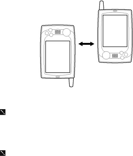
4-4. Infrared Communication
Transfer Items Using Infrared
Using infrared (IR), you can send and receive information, such as contacts and appointments, between two Windows-powered Pocket PCs.
To send information
1.Switch to the program where you created the item you want to send and locate the item in the list. If you want to send more than one item, drag the stylus across the items you want to send.
2.Align the IR ports so that they are unobstructed and within a close range.
∙ The two infrared ports should be within about 30cm from each other.
3. Tap and hold the item, and tap Send via Infrared on the pop-up menu.
You can also send items, but not folders, from File Explorer. Tap and hold the item you want to send, and then tap Send via Infrared on the pop-up menu.
To receive information
1.Align the IR ports so that they are unobstructed and within a close range.
2.Tap  , Programs, and then Infrared Receive.
You can also receive items from Tasks, Contacts, Calendar, and Notes by tapping Tools and then Receive via Infrared in list view.
— 11 —
5. ADJUSTMENT
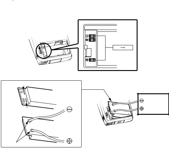
5-1. Setting (Adjusting) DC Voltage to AD converter
The following operation are not only for Check, but also for setting (adjusting) for DC voltage to AD converter in CPU.
When calibration for touch panel, battery voltage detection and so on are not correctly performed, try to check and perform these settings (adjustments).
Prepare one (or two) DC voltage stabilizers for Main/Sub battery power supply.
Important 
These settings (adjustments) for the main PC Board Assembly has not be performed in the factory. Therefore, be sure to perform this setting (adjustment) whenever you replace the main PC Board Assembly.
1. Remove the rechargeable main battery and AC adapter.
4.2 V |
3.7 V |
From
Power Stabilizer
How to supply main voltage
Cut the lines
Mainbattery
Cut the lines
Mainbattery
To POWER
Stabilizer
Make hole and connect wire
How to make/use dummy Main battery
2.Using a stylus pen, slide the main battery as shown above.
3.Using DC voltage stabilizer, supply DC voltage (4.2V) to  terminal as shown above. Turn on the unit's power. After that, it is recommended to perform RESET or FULL RESET operation.
4.Booting the diagnostic program, display Main Menu for the operation check.
5.Make the voltage power supply added to the main battery terminal 4.2 V ± 0.05 V.
6.Tapping voltage Write, the following display appears.
*** <AD Revision Value Write> ***
<Max Level Write>
Voltage Write-> Contacts Key
Escape -> ON Key
— 12 —

7. Pressing Contacts button, the following display appears.
*** <AD Revision Value Write> ***
<Max Level Write>
AD Value Read! 0x8...
<Min Level Write>
Voltage |
Write-> Contacts Key |
Escape |
-> ON Key |
If the unit can not read the voltage 4.2V correctly, "No Good. Please retry!!" message will appear. Note that the unit can not be progressed in the next stage whenever this message appears.
8.Make the voltage power supply added to the main battery terminal 3.7V ± 0.05V. Then, press Contacts button again.
Doing so, the following display appears.
*** <AD Revision Value Write> ***
<Max Level Write> |
|
|
AD Value Read! |
0x8... |
|
<Min Level Write> |
|
|
AD Value Read! |
0x8... |
|
Voltage Write-> Contacts Key |
||
Escape |
-> ON Key |
|
9.Make the voltage power supply added to sub battery terminal 2.7 V ± 0.05 V by using dummy sub battery. (Refer to following figure for connection)
Note: Main power can be supplied from Ac adapter or main battery.
Battery holder
 Large plate
To power stabilizer
Then, press Contacts button again. Doing so, the following display appears.
*** <AD Revison Value Write> ***
<Max Level Write> |
|
AD Value Read! |
**** |
<Min Level Write> |
|
AD Value Read! |
**** |
<SUB Level Write> |
|
AD Value Read! |
**** |
Write Data Value |
|
Max=**** ;SUb=**** |
|
Min=**** |
|
 Insulata plate
 Small plate
10.Pressing Action Control button, the following display appears along with Main Menu display (under Main Menu display).
AD Code=OOOOO
If missed, the following # display will appear instead of O.
AD Code=# # # # #
If the display appears, be sure to try to perform these settings (adjustments) again. After turning off the unit power, stop to add the powers to the unit.
Finally, after connecting the rechargeable main battery and AC adapter to the unit, perform Initial Setup or
FULL RESET.
—13 —

5-2. Display adjustment
1.Perform diagnosis program Main Menu 1 DISPLAY.
2.By tapping touch panel 8 times, the display color becomes GRAY.
3.If abnormal displays (flicker, vertical stripe and so on) are detected, change Vcom voltage rotating the variable resistor VR300. (refer to location as show figure)
To adjust actually, removing the screws assembled onto the lower case, disassemble the unit as shown below. Then rotate this variable resistor (VR300) using a ceramic screw driver (minus/ 1.8 mm width) to make the screen the normal display (no flicker and no stripes).
— 14 —

6.OPERATION CHECK
6-1. Preparation
1.SX45 (Prepare another units to perform IrDA communication check except the checking unit.)
2.Compact Flash Memory Card
3.SD Memory Card
4.Rechargeable battery pack (L36880-N9001-A106)
5.AC adapter (L36880-N9001-A108)
6.Cradle (L36880-N9001-A103) with serial cable (L36880-N9001-A104)
7.Diagnostic program files for SX45 with compact Flash Memory Card
8.Head set
9.One DC Power Supply Stabilizers
10.Screw driver (Y type)
11.Ampere meter/Volt meter
12.USB cable (L36880-N9001-A105)
NOTES:
*Be sure to make back-up copies of all data in the unit before repair using BACKUP/ RESTORE function in ActiveSync 3.1 software because FULL RESET must be performed to finish or abort this operation check. Diagnostic program file will be saved in RAM assembled onto the main PC board.
Therefore, performing FULL RESET after this check, this program should be deleted.
These program files (DKP700.exe/ Diag.exe/ DiagRF.exe) will be supplied along with the CF card.
*The unit may be locked during the installation, this check or the other operation. If this lock occur, try to perform RESET or FULL RESET operation.
6-2. How to install the diagnostic program
Important: There are two kinds of diagnosis program for English version and German version. Make sure the version when the diagnosis program is loaded to the unit.
< Diag installation & Start up, Exit and Change >
Seq. |
Operation |
Display |
|
|
|
|||
|
|
|
|
|
|
|
|
|
|
< Diag set and Start up > |
|
|
|
|
|
|
|
1 |
Perform full reset |
Initial display (welcome) comes up after |
||||||
|
|
full reset |
|
|
|
|||
2 |
Insert CF card which |
Autorun for DKP700 comes up, |
||||||
|
including Diag. Program |
then return to intial display again |
||||||
|
|
|
|
|
|
|
|
|
|
|
|
Autorun for DKP700 v1.01 |
|
||||
|
|
|
|
|
|
|
|
|
|
|
|
Run Autorun.exe? |
|
||||
|
|
|
DKP700.exe |
|
|
|
||
|
|
|
Diag.exe |
|
|
|
||
|
|
|
DiagRF.exe |
|
|
|
||
|
|
|
|
|
|
|
|
|
|
|
|
|
Yes |
|
No |
|
|
|
|
|
|
|
|
|
|
|
|
|
|
|
|
|
|
|
|
|
|
|
|
|
|
|
|
|
— 15 —
3 |
Tap diplay according to instruction of |
Autorun for DKP700 message |
||||||||
|
display message and set up intial setting |
again. |
|
|
|
|
||||
|
for SX45 |
|
|
|
|
|
|
|
|
|
4 |
Tap Yes |
Soft Reset message comes up |
||||||||
|
|
|
|
|
|
|
|
|
|
|
|
|
|
Soft Rest |
|
|
|
|
|||
|
|
|
|
|
|
|
|
|
|
|
|
|
|
After Remove CF- |
|
||||||
|
|
|
card, |
|
|
|
|
|||
|
|
|
Push [Yes] button. |
|
||||||
|
|
|
|
|
|
|
|
|
|
|
|
|
|
|
Yes |
|
No |
|
|
|
|
|
|
|
|
|
|
|
|
|
|
|
|
|
|
|
|
|
|
|
|
|
|
5 |
Remove CF card, then tap |
Error on GSM connection message |
||||||||
|
Yes |
comes up |
|
|
|
|
||||
6 |
Disregard the error and Tap OK |
Diag Chg message comes up |
||||||||
|
|
|
|
|
|
|
|
|
||
|
|
|
Diag Chg |
|
|
|
|
|||
|
|
|
|
|
|
|
|
|||
|
|
|
|
|
|
|
|
|||
|
|
|
|
|
DKP700 |
|
|
|||
|
|
|
|
|
|
|
|
|||
|
|
|
|
|
|
|
|
|||
|
|
|
|
|
DIAG.exe |
|
|
|||
|
|
|
|
|
|
|
|
|||
|
|
|
|
|
|
|
||||
|
|
|
|
|
DiagRF.exe |
|
|
|||
|
|
|
|
|
|
|
||||
|
|
|
|
|
|
|
|
|
|
|
7 |
Tap DIAG.EXE |
** Main Menu ** comes up |
||||||||
|
(As for DKP700 operation, refer to |
1 DISPLAY |
|
|
|
|
||||
|
Chaptor 6-4.) |
2 TOUCH PANEL |
|
|
|
|
||||
|
|
3 MEMORY |
|
|
|
|
||||
|
|
4 SERIAL |
|
|
|
|
||||
|
|
5 POWER CONTROL |
||||||||
|
|
6 AUDIO |
|
|
|
|
||||
|
|
7 OTHERS |
|
|
|
|
||||
|
|
8 COLOR BAR |
|
|
|
|
||||
|
|
9 VOLTAGE Write |
|
|
|
|
||||
|
|
10 |
|
|
|
|
|
|
|
|
|
|
11 T E S T AC |
|
|
|
|
||||
|
|
12 |
|
|
|
|
|
|
|
|
|
|
13 DIAG EXIT |
|
|
|
|
||||
|
|
14 DIAG CHANGE |
||||||||
|
|
|
|
|
|
|
|
|
|
|
NOTE: As for another operation check, refer to page 25. |
|
|
|
|
|
|
|
|
|
|
— 16 —
8 |
Tap 11TEST AC |
** TEST AC ** comes up |
|
|
|
1 Power Control |
|
|
|
2 Switch |
|
|
|
3 Loop Back |
|
|
|
4 Loop Back 2 |
|
|
|
5 USB Check |
|
|
|
6 LR-Channel |
|
|
|
7 Record |
|
|
|
8 Color Bar |
|
|
|
9 Keyboard Random Plus |
|
|
|
10 ROM Sum/Bus/Type |
|
|
|
11 RAM Test |
|
|
|
12 SD Check |
|
|
|
13 RSSI LED Check |
|
|
|
14 Touch Panel Point |
|
|
|
15 |
Back Light |
|
|
16 |
Voltage Write |
|
|
17 |
Interactive <IrDA Ck> |
|
|
18 |
Send/Receive 2 <FIR Ck> |
|
|
19 |
|
|
|
20 |
|
|
|
21 |
Return to Main Menu |
|
|
|
|
|
< Diag Exit and Change > |
|
|
1 |
Tap 21 Return to Main Menu |
Return to ** Main Menu ** |
|
|
|
1 DISPLAY |
|
|
|
2 TOUCH PANEL |
|
|
|
3 MEMORY |
|
|
|
4 SERIAL |
|
|
|
5 POWER CONTROL |
|
|
|
6 AUDIO |
|
|
|
7 OTHERS |
|
|
|
8 COLOR BAR |
|
|
|
9 VOLTAGE Write |
|
|
|
10 |
|
|
|
11 T E S T AC |
|
|
|
12 |
|
|
|
13 |
DIAG EXIT |
|
|
14 |
DIAG CHANGE |
2 |
Tap 13 DIAG EXIT |
Return to intial display |
|
3 |
Tap 14 DIAG CHANGE |
Return to Diag Chg menu |
|
|
|
|
|
Important : If something inoperative performances occur during excution, “Reset” or “Full Reset” should be done. Then the program can be worked again.
— 17 —
6-3. Operation Check
■1 Power control
Current Consumption should be checked.
No. |
Operation |
|
Display |
Check |
If NG |
|
|
|
|
|
|
1 |
Connect terminals of main |
** TEST AC ** comes up |
Measure the main battery |
Main PCB |
|
|
battery to Power Stabilizer. |
1 |
Power Control |
current in page 2 for the details. |
fault |
|
|
2 |
Switch |
|
|
|
|
3 |
Loop Back |
|
|
|
|
4 |
Loop Back 2 |
|
|
|
|
5 |
USB Check |
|
|
|
|
6 |
LR-Channel |
|
|
|
|
7 |
Record |
|
|
|
|
8 |
Color Bar |
|
|
|
|
9 |
Keyboard Random Plus |
|
|
|
|
10 ROM Sum/Bus/Type |
|
|
|
|
|
11 RAM Test |
|
|
|
|
|
12 SD Check |
|
|
|
|
|
13 RSSI LED Check |
|
|
|
|
|
14 Touch Panel Point |
|
|
|
|
|
15 Back Light |
|
|
|
|
|
16 Voltage Write |
|
|
|
|
|
17 Interactive <IrDA Ck> |
|
|
|
|
|
18 Send/Receive 2 <FIR Ck> |
|
|
|
|
|
19 |
|
|
|
|
|
20 |
|
|
|
|
|
21 Return to Main Menu |
|
|
|
|
|
|
|
|
|
2 |
Tap the touch panel on 1 |
Currently CPU clock is |
Measure the main battery |
|
|
|
POWER CONTROL. |
150MHz |
current in page 2 for the details. |
|
|
|
|
VTCLK is 50MHz |
|
|
|
|
|
|
|
|
|
3 |
Turn to OFF (stand by) the |
No display |
Measure the main battery |
|
|
|
unit. |
|
|
current in page 2. |
|
|
|
|
|
|
|
4 |
Press down the ACTION |
Return to TEST AC MENU. |
|
|
|
|
key. |
|
|
|
|
|
|
|
|
|
|
■2 Switch
Switch condition should be checked.
No. |
Operation |
Display |
Check |
If NG |
||
|
|
|
|
|
|
|
1 |
Tap the touch panel on 2 |
|
|
Check on red blinking of |
LED PCB, |
|
|
Switch. |
|
|
Notification LED. |
Main PCB |
|
|
|
|
|
Check on “VDETS OFF”. |
fault |
|
|
|
|
|
|
||
2 |
Insert the AC adapter. |
AC Adpter USED |
Check on “USED.” |
Adaptor |
||
|
|
|
|
Check if Charge LED turns on. |
Jack |
|
|
|
|
|
|
fault |
|
3 |
Remove the AC adapter. |
AC Adpter |
NOT USED |
Check on “NOT USED.” |
||
|
||||||
|
|
|
|
Check if Charge LED turns off. |
|
|
|
|
|
|
|
|
|
4 |
Move the battery cover |
Cover |
OPEN |
Check on “OPEN.” |
Card PCB |
|
|
LOCK dial to Main Battery |
|
|
|
fault |
|
|
Replacement. |
|
|
|
|
|
|
|
|
|
|
|
|
5 |
Move the battery cover |
Cover |
CLOSE |
Check on “CLOSED.” |
|
|
|
LOCK dial to LOCK. |
|
|
|
|
|
6 |
Insert the head set. |
Audio Jack |
ON |
Check on “ON.” |
Main PCB |
|
|
|
|
|
|
fault |
|
7 |
Press the HOOK button of |
ONHOOK |
ON |
Check on “ON.” |
||
|
||||||
|
the head set. |
|
|
|
|
|
|
|
|
|
|
|
|
8 |
Pull out the Audio Jack. |
Audio Jack |
OFF |
Check on “OFF.” |
|
|
|
|
|
|
|
||
9 |
Press down the ACTION |
Return to TEST AC MENU. |
|
|
||
|
key. |
|
|
|
|
|
— 18 —
■3 Loop Back
Serial Connector condition should be checked.
No. |
Operation |
Display |
Check |
If NG |
|
|
|
|
|
1 |
Insert the cradle loop back |
|
|
20 pin |
|
jig into the 20 pin |
|
|
Connector |
|
connector. |
|
|
fault |
|
|
|
|
|
2 |
Tap the touch panel on 3 |
RS232C ---> OK |
Check if all 4 lines show OK. |
|
|
Loop Back. |
DTR-DCD --->OK |
|
|
|
|
DTR-DSR --->OK |
|
|
|
|
DTR-CTS ---> OK |
|
|
|
|
|
|
|
3 |
Press down the ACTION |
|
|
|
|
key. |
|
|
|
|
|
|
|
|
4 |
Remove the loop back jig. |
|
|
|
|
|
|
|
|
5 |
Press down the ACTION |
Return to TEST AC MENU. |
|
|
|
key. |
|
|
|
|
|
|
|
|
■4 Loop Back2
Cradle Connector condition should be checked.
No. |
Operation |
Display |
Check |
If NG |
|
|
|
|
|
|
|
1 |
Insert the loop back2 jig |
|
|
20 pin |
|
|
into the 20 pin connector. |
|
|
Connector |
|
|
|
|
|
fault |
|
2 |
Tap on the touch panel on |
*** LOOP BACK2 *** |
Check if the top line shows OK, |
||
|
|||||
|
4 Loop Back2. |
---> LOOP BACK2 OK |
or check if the rest of the lines |
|
|
|
|
MPX1-9 pin ---> OK |
show OK. |
|
|
|
|
SEL0 pin ---> OK |
|
|
|
|
|
SEL1 pin ---> OK |
|
|
|
|
|
SEL2 pin ---> OK |
|
|
|
|
|
|
|
|
|
3 |
Remove the loop back2 jig. |
|
|
|
|
|
|
|
|
|
|
4 |
Press down the ACTION |
Return to TEST AC MENU. |
|
|
|
|
key. |
|
|
|
|
|
|
|
|
|
■5 USB Check
USB condition should be checked.
No. |
Operation |
Display |
Check |
If NG |
|
|
|
|
|
1 |
Tap the touch panel on 5 |
*** USB CHECK *** |
|
20 pin |
|
USB Check. |
|
|
Connector |
|
After the message in the |
Please connect USB cable |
|
fault |
|
|
|
||
|
right is displayed, connect |
with PC starts with the |
|
|
|
the USB cable to the 20 |
Action key |
|
|
|
pin connector of the main |
|
|
|
|
body. |
|
|
|
|
Connect the USB |
GD23sp(CONF)=1 |
|
|
|
connector to the USB port |
USB TEST................ OK |
Check on OK. |
|
|
of the computer. |
|
|
|
|
Press down the ACTION |
|
|
|
|
key. |
|
|
|
|
|
|
|
|
2 |
Remove the USB tool. |
|
|
|
|
|
|
|
|
3 |
Press down the ACTION |
Return to TEST AC MENU. |
|
|
|
key. |
|
|
|
|
|
|
|
|
Note: In No. 1, do not connect the USB tool before “Tap the touch panel on 5 USB Check”, or USB TEST becomes NG.
— 19 —
6 LR-Channel
Audio sounds should be checked.
No. |
Operation |
Display |
Check |
If NG |
|
|
|
|
|
|
|
1 |
Insert the head set. |
|
|
Main PCB |
|
|
|
|
|
fault |
|
2 |
Tap on the touch panel on |
AUDIO LR_Chanel |
Check if the sound in the Right |
||
|
|||||
|
6 LR-Channel. |
|
Channel can be heard from the |
|
|
|
|
|
right ear phone and the sound |
|
|
|
|
|
in the Left Channel can be |
|
|
|
|
|
heard from the left ear phone. |
|
|
|
|
|
|
|
|
3 |
Press down the ACTION |
Return to TEST AC MENU. |
|
|
|
|
key. |
|
|
|
|
|
|
|
|
|
7 Record
Record and Play back sound should be checked.
No. |
Operation |
|
Display |
Check |
If NG |
|
|
|
|
|
|
1 |
Tap on the touch panel on |
1 |
Start Recording |
|
Main PCB |
|
7 Record. |
2 |
Play Recording Sound |
|
fault |
|
|
Exit to Action key push! |
|
|
|
|
|
|
|
|
|
2 |
Tap on the touch panel on |
Action key push to stop |
|
|
|
|
1 Start Recording. Input |
Recording |
|
|
|
|
any sound into the inner |
The recorded sound |
|
|
|
|
microphone. |
automatically stops in |
|
|
|
|
|
about five seconds. |
|
|
|
|
|
|
|
|
|
|
Press the ACTION key. |
1 |
Start Recording |
|
|
|
|
2 |
Play Recording Sound |
|
|
|
|
Exit to Action key push! |
|
|
|
|
|
|
|
|
|
3 |
Tap on the touch panel on |
Action key push to stop |
Check if the recorded sound |
|
|
|
2 Play Recorded Sound. |
Playing |
plays normally (check it by the |
|
|
|
|
The Played sound |
head set). |
|
|
|
|
automatically stops in |
|
|
|
|
|
about five seconds. |
|
|
|
|
|
|
|
|
|
4 |
Press the ACTION key. |
Return to TEST AC MENU. |
|
|
|
|
|
|
|
|
|
8 COLOR BAR
Color condition should be checked.
No. |
Operation |
Display |
Check |
If NG |
|
|
|
|
|
1 |
Tap on the touch panel on |
The color bar of RGB is |
Check if the coloring is normal. |
LCD unit |
|
8 COLOR BAR. |
indicated. |
Check if the gradation of color |
fault |
|
|
|
in the right is smooth. |
|
|
|
|
|
|
2 |
Above condition |
Blight = 142 |
The Bright Value is indicated in |
|
|
|
the lower part of the screen. |
|
|
|
|
|
|
|
|
|
|
|
|
3 |
Press ACTION Key or |
|
Check on the contrast which |
|
|
Cross Up Key. |
Blight = |
becomes darker as the Bright |
|
|
|
|
Value increases. |
|
|
|
|
|
|
4 |
Press ACTION Key or |
|
Check on the contrast which |
|
|
Cross Up Key. |
Blight = |
becomes lighter as the Bright |
|
|
|
|
Value decreases. |
|
|
|
|
|
|
5 |
Press the ACTION key. |
Return to TEST AC MENU. |
|
|
|
|
|
|
|
9 Keyboard Random Plus is not checked.
— 20 —

10 ROM Sum/Bus/Type ROM should be checked.
No. |
Operation |
Display |
Check |
If NG |
|
|
|
|
|
|
|
1 |
Tap on the touch panel on |
<JX707> Select |
<JX700> Select |
|
ROM |
|
10 ROM SUM/BUS/Type. |
|
PCB |
||
|
TAP This Area! |
TAP This Area! |
|
||
|
|
32MB FLASH ROM |
16MB FLASH ROM |
|
fault |
|
|
|
|
||
|
|
|
|
|
|
2 |
Tap on the touch panel in |
ROM CHECK SUM |
Check on OK. |
|
|
|
the right. |
|
|
Refer to exact value in page 2. |
|
|
|
base addr. sum value |
|
|
|
|
|
SUM1(be000000) = |
|
|
|
|
|
SUM1(be000000) = |
|
|
|
|
|
FLASH Write ---> OK |
|
|
|
|
|
|
|
|
|
3 |
Press the ACTION key. |
Return to TEST AC MENU. |
|
|
|
|
|
|
|
|
|
11 RAM Test
RAM should be checked.
No. |
Operation |
Display |
Check |
If NG |
|
|
|
|
|
1 |
Tap on the touch panel on |
RAM CHECK |
|
Main PCB |
|
11 RAM TEST. |
-- RAM CHK OK -- |
Check on OK. |
fault |
|
|
|
||
|
|
|
|
|
2 |
Press the ACTION key. |
Return to TEST AC MENU. |
|
|
|
|
|
|
|
12 SD Check
SD card should be checked.
No. |
Operation |
Display |
Check |
If NG |
|
|
|
|
|
1 |
Insert the SD card with |
|
|
Card PCB |
|
write protect OFF. |
|
|
fault |
|
|
|
|
|
2 |
Tap on the touch panel on |
Clock; 9.216MHz...CMD9 OK ;CMD10 OK |
Check on OK. |
|
|
12 SD CHECK. |
Clock; 4.608MHz...CMD9 OK ;CMD10 OK |
|
|
|
|
Clock; 2.304MHz...CMD9 OK ;CMD10 OK |
|
|
|
|
Clock; 1.152MHz...CMD9 OK ;CMD10 OK |
|
|
|
|
Clock; 0.576MHz...CMD9 OK ;CMD10 OK |
|
|
|
|
Clock; 0.288MHz...CMD9 OK ;CMD10 OK |
|
|
|
|
|
|
|
3 |
Press the ACTION key. |
Return to TEST AC MENU. |
|
|
|
Pull out the SD card. |
|
|
|
|
|
|
|
|
— 21 —
 Loading...