


XE-A404
SERVICE MANUAL
(XE-A404)
(XE-A505)
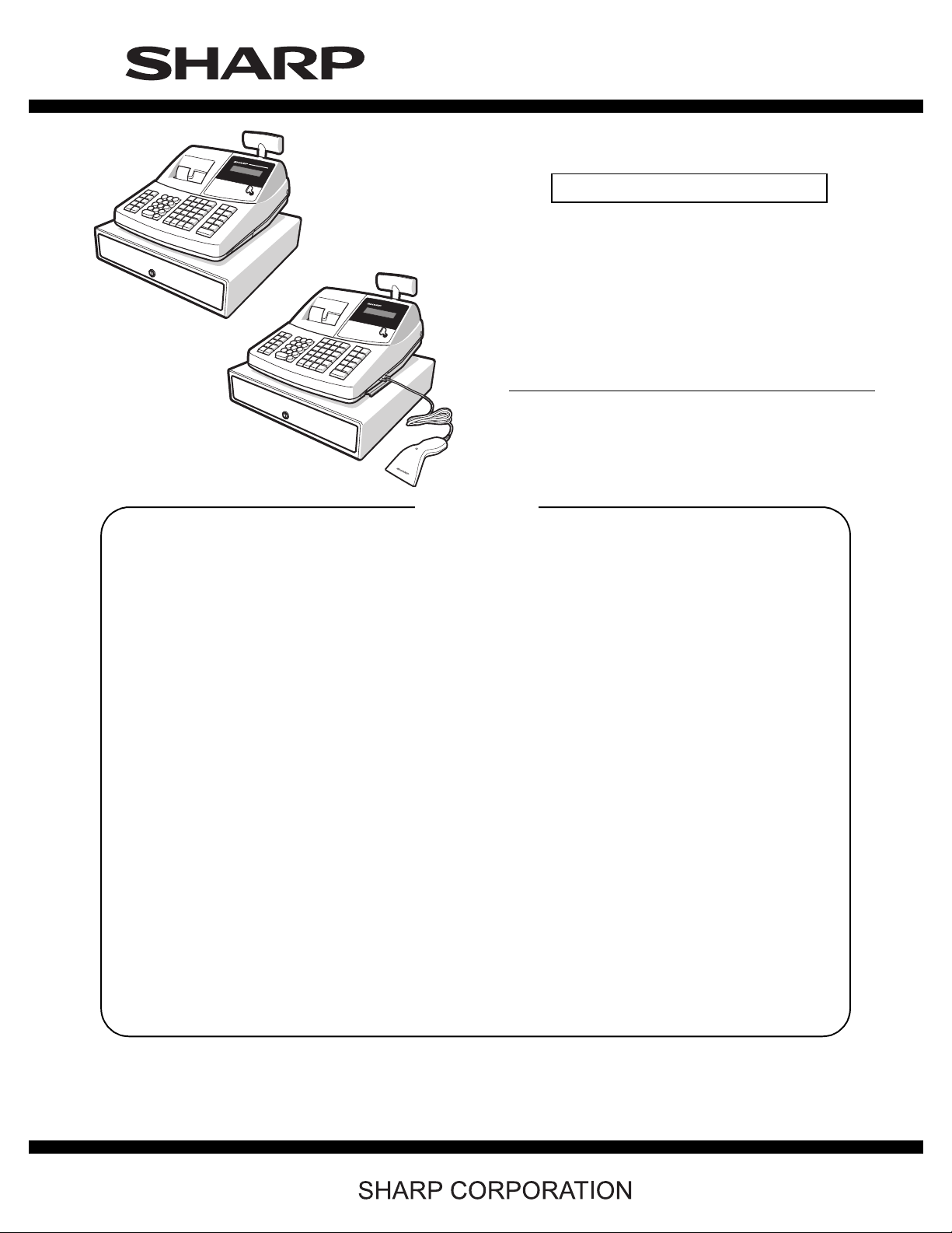
MODEL XE-A505
CONTENTS
CODE : 00Z
LEAD-FREE SOLDER MODEL
XEA404USME
ELECTRIC
CASH REGISTER
XE-A404
SRV KEY
PRINTER
(U version)
: Not necessary
: PR-45MII
■ LEAD-FREE SOLDER
CHAPTER 1. SPECIFICATIONS . . . . . . . . . . . . . . . . . . . . . . . . . . . . 1
CHAPTER 2. OPTIONS . . . . . . . . . . . . . . . . . . . . . . . . . . . . . . . . . . . 4
CHAPTER 3. MASTER RESET AND PROGRAM RESET. . . . . . . . . 4
CHAPTER 4. HARDWARE DESCRIPTION. . . . . . . . . . . . . . . . . . . . 5
CHAPTER 5. DIAGNOSTIC PROGRAM . . . . . . . . . . . . . . . . . . . . . 10
CHAPTER 6. CIRCUIT DIAGRAM AND PWB LAYOUT . . . . . . . . . 15
Parts marked with "!" are important for maintaining the safety of the set. Be sure to replace these parts with specified
ones for maintaining the safety and performance of the set.
This document has been pub lished to be used
for after sales service only.
The contents are subject to change without notice.

CAUTION
RISK OF EXPLOSION IF BATTERY IS REPLACED
BY AN INCORRECT TYPE.
DISPOSE OF USED BATTERIES ACCORDING
TO THE INSTRUCTIONS.
AVOID: SHORT-CIRCUITING THE BATTERY TERMINALS.
KEEP THE BATTERY AWAY FROM FIRE.
* WHEN DISPOSING THE BATTERY, FOLLOW THE LOCAL
RULES AND REGULATIONS.
“BATTERY DISPOSAL”
THIS PRODUCT CONTAINS NICKEL-METAL HYDRIDE BATTERY.
THIS BATTERY MUST BE DISPOSED OF PROPERLY.
REMOVE THE BATTERY FROM THE PRODUCT AND CONTACT FEDERAL OR
STATE ENVIRONMENTAL AGENCIES FOR INFORMATION ON RECYCLING AND
DISPOSAL OPTIONS.
XE-A404/A505 (U)
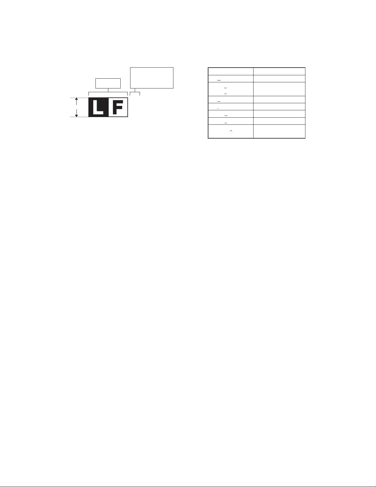
■ LEAD-FREE SOLDER
The PWB’ s of this model employs lead-free solder. The “LF” marks indicated on the PWB’s and the Service Manual mean “ Lead-Free” solder. The
alphabet following the LF mark shows the kind of lead-free solder.
Example:
<Solder composition code of lead-free solder>
Solder composition
Sn-Ag-Cu
Sn-Ag-Bi
Sn-Ag-Bi-Cu
Sn-Zn-Bi
Sn-In-Ag-Bi
Sn-Cu-Ni
Sn-Ag-Sb
Bi-Sn-Ag-P
Bi-Sn-Ag
5mm
Lead-Free
Solder composition
code (Refer to the
table at the right.)
a
(1) NOTE FOR THE USE OF LEAD-FREE SOLDER THREAD
When repairing a lead-free solder PWB, use lead-free solder thread. Never use conventional lead solder thread, which may cause a breakdown or an accident.
Since the melting point of lead-f ree solder thread is ab out 40°C highe r t han tha t of co nventional lead solder th read, the use o f the exclusive-use soldering iron is
recommendable.
(2) NOTE FOR SOLDERING WORK
Solder composition code
a
b
z
i
n
s
p
Since the melting point of lead-free solder is about 220°C, which is about 40°C higher than that of conventional lead solder, and its soldering capacity is inferior to
conventional one, it is apt to keep the soldering iron in contact with the PWB for longer time. This may cause land separation or may exceed the heat-resistive temperature of components. Use enough care to separate the soldering iron from the PWB when completion of soldering is confirmed.
Since lead-free solder includes a greater quantity of tin, the iron tip may corrode easily. Turn ON/OFF the soldering iron power frequently.
If different-kind solder remains on the soldering iron tip, it is melted together with lead-free solder. To avoid this, clean the soldering iron tip after com-
pletion of soldering work.
If the soldering iron tip is discolored black during soldering work, clean
and file the tip with steel wool or a fine filer.
XE-A404/A505 (U) LEAD-FREE SOLDER
PC-UM10M
–
CHAPTER 1. SPECIFICATIONS
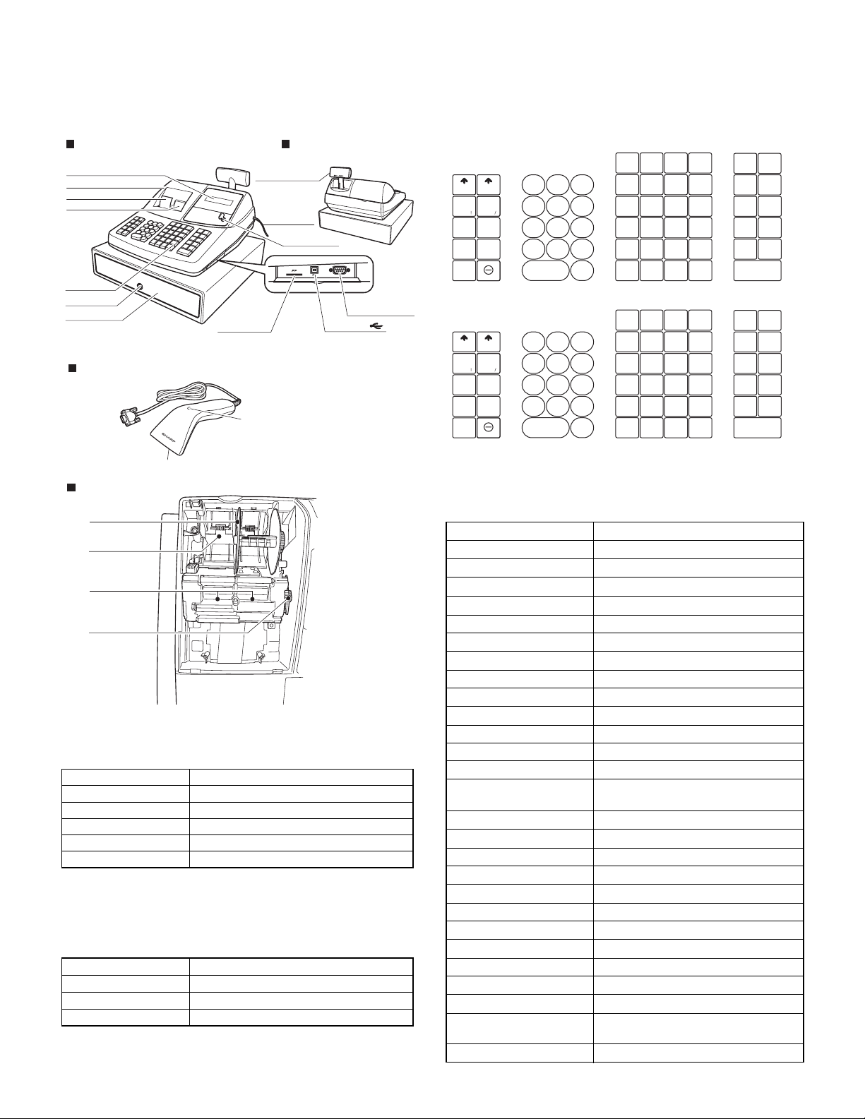
1. APPEARANCE
Register rear viewRegister front view
Operator display
Printer cover
Receipt paper
Journal window
Keyboard
Drawer lock
Drawer
Customer display
(Pop-up type)
SD memory
card slot
AC
power cord
Mode switch
SCANNER
Scanner port
(XE-A505 only)
USB port
Barcode scanner (XE-A505 ONLY)
Indicator
Lights red when a barcode is scanned.
Scanning window
Printer
Take-up spool
Paper roll cradle
Paper chute
Print head
release lever
2. RATING
Model XE-A404/A505
Weight 12.5 kg
Dimensions 420 (W) x 430 (D) x 302 (H) mm
Power source AC 120V, 60Hz
Power consumption Stand-by 10.0W, Operating 44.0W (max.)
Working temperature 32 °F to 104 °F (0 °C to 40 °C)
3. KEYBOARD
3-1. KEYBOARD LAYOUT
Type Normal keyboard
Key position STD/MAX 59
Key pitch 19 (W) x 19 (H) mm
Key la yout Fixed type
3-2. KEY LIST
■Keyboard layout
[XE-A404]
RECEIPT JOURNAL
RA
%1
/AMT
RCPT
%2
/PO
NUMBER
-
VOID
RFND
SHIFT
DC
ESC
BS
SPACE
FOR
789
456
123
CL
0
00
.
@/
[XE-A505]
RECEIPT JOURNAL
RA
%1
/AMT
RCPT
%2
/PO
NUMBER
-
VOID
RFND
SHIFT
DC
ESC
BS
SPACE
FOR
789
456
123
CL
0
00
.
@/
Note: The small characters on the bottom or lower right in each key
indicates functions or characters which can be used for character
entries for text programming.
■Key names
KEY TOP DESCRIPTION
2 (RECEIPT)
2 (JOURNAL)
RA/AMT
RCPT/PO
VOID
ESC
%1, %2
RFND
-
@/FOR
n
CL
00, 0-9
PLU/SUB (XE-A404)
PLU/UPC (XE-A505)
DEPT#
DEPT SHIFT
CLK# CONV
Dept1-40
INQ
Ta x 1 SHIFT, Tax 2 SHIFT
AUTO
TAX
CHK
CH1, CH2
MDSE SBTL
#/TM SBTL
CA/AT/NS
PLU
DEPT
DEPT
/SUB
#
SHIFT
25
A
5 F3010 K3515 P4020
24
29
9
8
7
6
DEPT
9
8
7
6
34
G
L
14
28
33
H
M
13
27
32
I
N
12
26
31
J
O
11
DEPT
SHIFT
#
29
34
G
L
14
28
33
H
M
13
27
32
I
N
12
26
31
J
O
11
B
4
23
C
3
22
D
2
21
E
1
PLU
/UPC
25
A
5 F3010 K3515 P4020
24
B
4
23
C
3
22
D
2
21
E
1
CLK#
/CONV
19
18
17
16
CLK#
/CONV
19
18
17
16
39
Q
38
R
37
S
36
T
39
Q
38
R
37
S
36
T
AUTO
INQ
U
TAX2
TAX1
SHIFT
SHIFT
TAX CH
CHK CH
MDSE
#/TM
SBTL
SBTL
CA/AT/NS
AUTO
INQ
U
TAX2
TAX1
SHIFT
SHIFT
TAX CH
CHK CH
MDSE
#/TM
SBTL
SBTL
CA/AT/NS
YXV
1
ZW
2
YXV
1
ZW
2
Receipt paper feed key
Journal paper feed key
Received-on account/Amount key
Receipt print/Paid-out key
Void key
Escape key
Percent 1and 2 key
Refund key
Discount key
Multiplication key
Decimal point key
Clear key
Numeric Keys
PLU/Sub-department key (XE-A404)
PLU/UPC key (XE-A505)
Department code entry key
Department shift key
Clerk code entry/Conversion key
Department keys
Inquiry key
Tax 1 and 2 shift key
Automatic sequence key
Ta x key
Check key
Charge 1 and 2 keys
Merchandise subtotal key
Non-add code/Time disp lay/Subtotal
key
Total/Am ount tender/Non Sale key
XE-A404/A505 SPECIFICATIONS
1 –
PC-UM10M
–
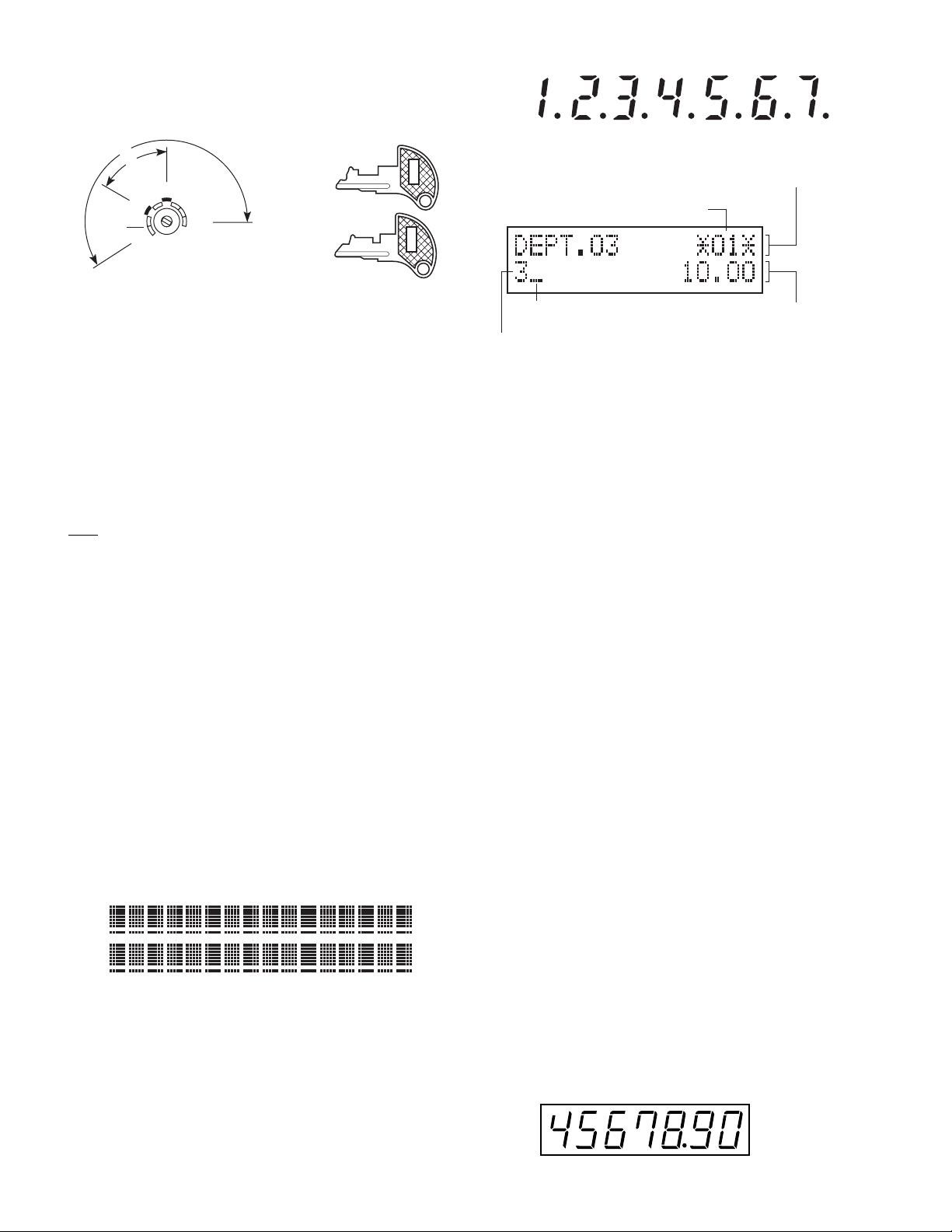
4. MODE SWITCH
4-1. LAYOUT
• Rotar y t ype
MA
OP
REG
OP
X/Z
PGM
MGR
X
1/Z1
X2/Z2
OFF
VOID
The mode switch can be operated by inserting one of the two supplied
mode keys - manager (MA) and operator (OP) keys. These keys can be
inserted or removed only in the “REG” or “OFF” position.
The mode switch has these settings:
OFF: This mode locks all register operations. (AC power turns off.)
No change occurs to register data.
OP X/Z: To take individual clerk X or Z reports, and to take flash
reports.
It can be used to toggle receipt state “ON” and “OFF” by press-
ing he [RCP/PO] key.
REG: For entering sales.
PGM: To program various items.
: Enters into the void mode. This mode allows correction after
VOID
finalizing a transaction.
MGR: For manager’s entries. The manager can use this mode for an
override entry.
X1/Z1: To take the X/Z report for various daily totals.
X2/Z2: To take the X/Z report for periodic (weekly or monthly) consoli-
dation.
Manager key (MA)
MA
Operator key (OP)
OP
5. DISPLAY
5-1. OPERATOR DISPLAY
Display device : STN LCD module
Number of line : 2 line
Number of digits : 16 positions
Color of display : Yellow Green / Orange
Character form : 5 x 7 dots
Character size : 8.06 (H) x 4.84 (W) mm
Layout:
5-2. CUSTOMER DISPLAY
Display device : LED
Number of line : 1 line
Number of digits : 7 digits
Color of display : Yellow Green
Style : Pop up type
Character form : 7 segment + Dp
Character size : 10.16mm (H) x 5.59mm (W)
Layout:
■Operator display
Function message display area
Clerk code or mode name
Receipt OFF indicator
Numeric entry display area
Repeat / Sentinel mark / Power save mark
• Clerk code or Mode name
The mode you are in is displayed. When a clerk is assigned, the
clerk code is displayed in the REG or OP X/Z mode. For example,
“*01*” is displayed when clerk 01 is assigned.
• Repeat
The number of repeats is displayed, starting at “2” and incremental
with each repeat. When you have registered ten times, the display
will show “0” (2 3 3......9 3 0 3 1 3 2...)
• Sentinel m ark
When amount in the drawer reaches the amount you prepro-
grammed, the sentinel mark “X” is displayed to advise you to
remove the money to a safe place.
• Power save mark
When the cash register goes into the power save mode, the power
save mark (decimal point) lights up.
• Function message display area
Item labels of departments and PLU/UPCs and function texts you
use, such as %1, (-) and CASH are displayed.
When an amount is to be entered, ------ is displayed at the numeric
entry area with a guidance message “ENTER PRICE”.
• Numeric entry display area
Numbers entered using numeric keys are displayed here.
Date and time display
Date and time appear on the display in the OP X/Z, REG, or MGR
mode. In the REG or MGR mode, press the [#/TM/SBTL] key to display the date and time.
Backlight of the LCD display
When an error occurs or the [RFND] or [VOID] key is pressed or enter
the void mode, the green backlight will turn red.
Error message
When an error occurs, the corresponding error message is displayed
in the function message display area.
■Customer display (Pop-up type)
XE-A404/A505 SPECIFICATIONS
2 –
PC-UM10M
–
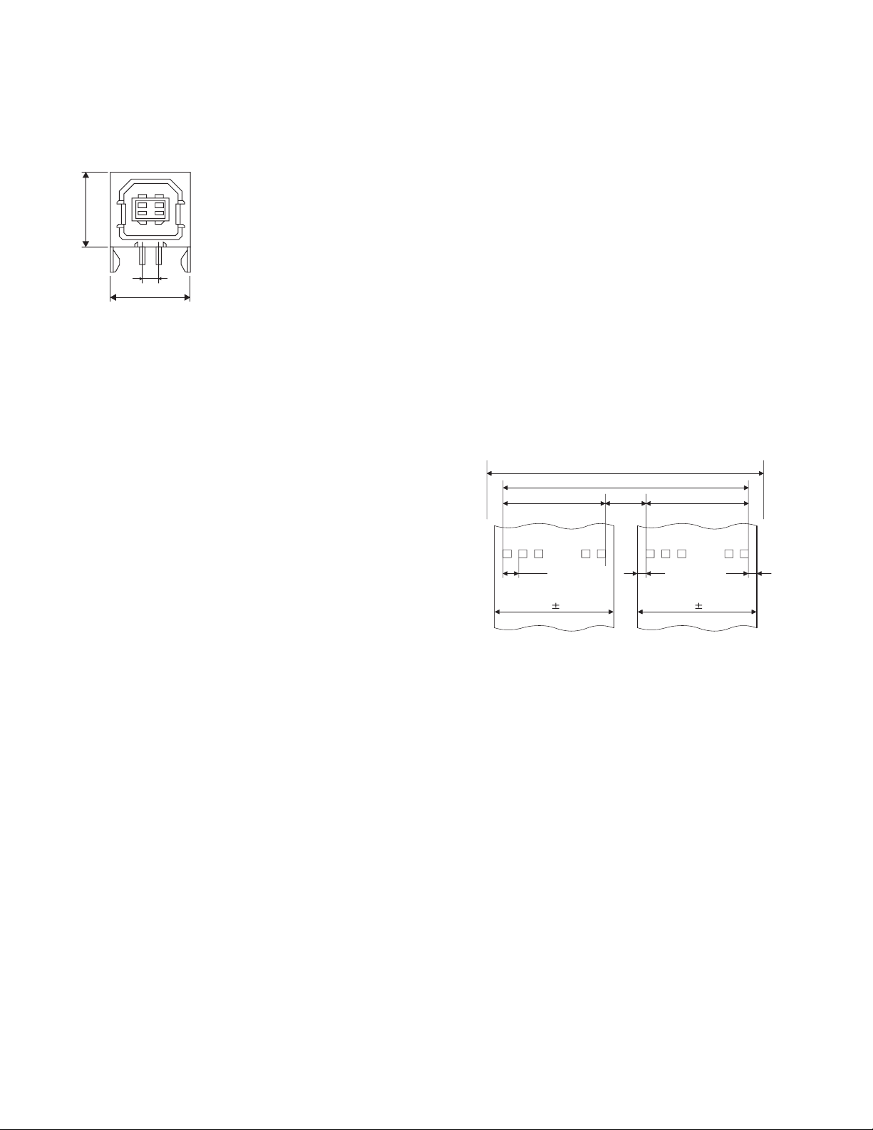
6. USB port
[DEVICE]
USB B Type
[OUTLINE]
This ECR has 1 port.
This is used in order to connect with a personal computer.
21
11.0
34
2.5
12.04
[SPECIFICATIONS]
1)Transmission rate : USB 2.0 Full Speed Max 12Mbps
2)Connector : USB B type
3)Pin assign : 1Pin 5V
: 2Pin -D
: 3Pin +D
: 4Pin GND
7. RS232 Scanner PORT (XE-A505 ONLY)
[DEVICE]
RS232 Scanner PORT
[OUTLINE]
XE-A505 has a RS232 Scanner port.
This port is use to scanner connection only.
XE-A404 hasn’t this port.
[SPECIFICATIONS]
Connector : DSUB 9PIN (MALE)
Data rate : 4800 (BPS)
Pin assign : 1Pin - CS
: 2Pin - RD
: 3Pin - SD
: 4Pin - GND
: 5Pin - GND
: 6Pin - GND
: 7Pin - RS
: 8Pin - N.C.
: 9Pin - +5V
8. PRINTER
8-1. PRINTER
• Part number : PR-45M II
• NO. of station : 2 (Receipt and journal)
• Validation : No
• Printing system : Line thermal
• No. of dot : Receipt 288 dots
Journal 288 dots
• Dot pitch : Horizontal 0.125mm
Vertical 0.125mm
• Font : 10 dots (W) u 24 dots (H)
• Printing capacity : Receipt max. 24 characters
Journal max . 24 characters
• Character size : 1.25mm (W) u 3.0mm (H) at 10 u 24 dots
• Print pitch : Column distance 1.5mm
Row distance 3.75mm
• Print speed : Approximate 50mm/s (13.3 lines/sec)
• Paper feed speed : Approximate 40mm/s
(Manual feed)
• Reliability : Mechanism MCBF 5 million lines
• Paper end sensor : Set up (Receipt and journal)
• Cutter : Manual
• Near end sensor : No
Head life 12.5 million characters
(at 4 dots/1 character/1 element)
8-2. PAPER
• Paper roll dimension: 44.5 m 0.5mm in width
• Paper quality : (Journal/Receipt)
Max. 80mm in diameter
High-quality paper
paper thickness: 0.06 to 0.08mm
Nihon seisi thermal paper : TF50KS-E
Oii thermal paper : PD150R,
PD160R
8-3. LOGO STAMP
• No
8-4. CUTTER
• Method : Manual
8-5. PRINTING AREA
Receipt & Journal
Number of themal head heater elements 864 dots
(688dots)
4
3614
(288dots)
44.5 0.5
Journal
(units;mm)
(288dots)
0.125
44.5 0.5
Receipt
36
(112dots)
9. SD MEMORY CARD SLOT
[DEVICE]
SD Card (Version. 1.01)
[OUTLINE]
XE-A404/A505 has a SD Memory Card Slot.
[SPECIFICATIONS]
Variable cloc k rate : 0-25MHz
Other commands and memory access : 2.7-3.6V
Bus Protocol : SPI Bus
Correspondence capacity : 256MB-512MB
Recommended manufacturer : SanDisk
10.DRAWER
[OUTLINE]
• Standard equipment: Y es
• Max. number of additional drawers: 1
• The drawer consists of:
1) Drawer box (outer case) and drawer
2) Coin case
3) Money case
4) Lock (attached to the drawer)
4.5
XE-A404/A505 SPECIFICATIONS
3 –
PC-UM10M
–
[SPECIFICATION]
10-1.DRAWER BOX AND DRAWER
Model name of the drawer box SJ423
Size
color Gray (PB-N8.0)
Material Metal
Bell –
Release lever Standard equipment: situated at
Drawer open sensor –
420 (W) x 427 (D) x 114 (H) mm
the bottom
10-2.MONEY CASE
Separation from the drawer Disallowed
Separation of the bill compartments from the coin
compartments
Bill separator –
Number of compartments 5B/6C
5B/6C
Allowed
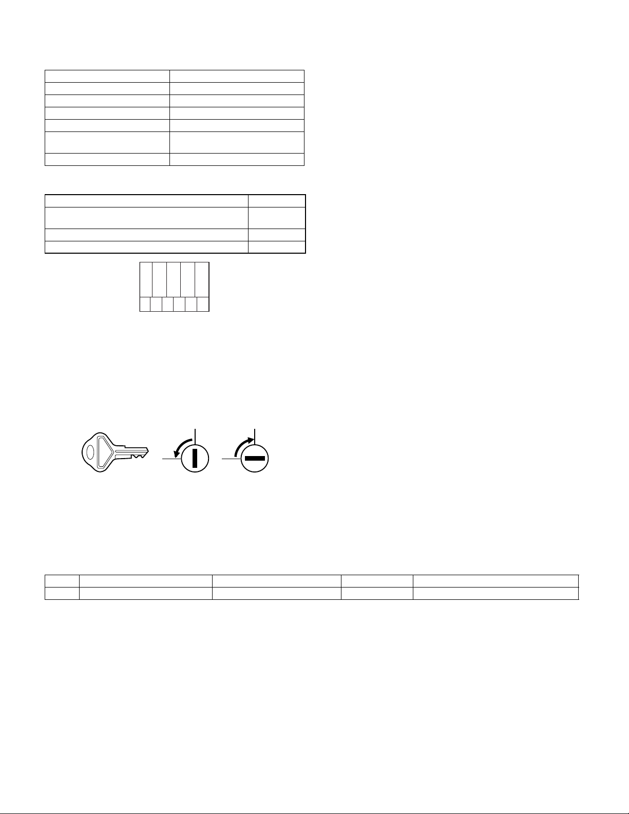
10-3.LOCK (LOCK KEY : LKGIM7331BHZZ)
• Location of the lock: Front
• Method of locking and unlocking:
To lock, inser t the drawer lock key into the lock
and turn it 90 degrees counter clockwise.
To unlock, inser t the drawer lock key and turn it
90 degrees clockwise.
•Key No: SK1
SK1-1
k
c
o
L
k
c
o
l
n
u
11.BATTERY
11-1.MEMORY BACK UP BATTERY
Type : Rechargeable battery
Number of battery : 1pcs as standard RBRC license
12.SCANNER (XE-A505 ONLY)
Barcode CCD Scanner an RS-232 interface.
This scanner is the handy barcode reader which can automatic-discriminate various barcodes and can read them, and is equipped with the
RS-232 communication interface.
[SPECIFICATIONS]
Light source : 660nm visble red LED with foc us light bar
Sensor : 2088 Pixels CCD arrays
Operating Voltage : +5V DC m 5%
Readable barcodes :EAN 8, EAN 13, UPC-A, UPC-E, CODABAR,
STANDARD 2 OF 5, CODE39, CODE93,
CODE128, INTERLEAVED 2 OF 5 ...... (P)
Weight : 120g m 5g (without cable) ...... (P)
Cable : 210cm in length, straight ...... (P)
Interface : RS-232 serial port interface
Connector : DSUB 9 pin
1 pin - RTS
2 pin - TXD
3 pin - RXD
4 pin - (4-6pin short)
5 pin - SG (Signal GND)
6 pin - (4-6pin short)
7 pin - CTS
8 pin - N.C.
9 pin - +5V
CHAPTER 2. OPTIONS
1. OPTIONS (NONE)
2. SERVICE OPTIONS (NONE)
3. SUPPLIES
NO NAME PARTS CODE PRICE RANK DESCRIPTION
1 Thermal roll paper TPAPR6645RC05 AY 5 ROLLS/PACK
4. SPECIAL SERVICE TOOLS (NO)
CHAPTER 3. MASTER RESET AND PROGRAM RESET
1. MASTER RESETTING
Master resetting clears the entire memory and resumes initial values.
Master resetting can be accomplished by using the following procedure:
Procedure A: 1) Unplug the AC cord from the wall outlet.
2) Set the mode switch to the PGM position.
3) While holding down both the JOURNAL FEED key
and [CL] key, plug in the AC cord to the wall outlet.
XE-A404/A505 OPTIONS
2. PROGRAM RESETTING (INITIALIZATION)
This resetting resumes the initial program without clearing memory.
This resetting can be operated at below sequence in PGM mode.
Procedure: 1) Unplug the AC cord from the wall outlet.
2) Set the mode switch to the PGM position.
3) While holding down both JOURNAL FEED key and
RECEIPT FEED key, plug in the AC cord to the wall
outlet.
4 –
PC-UM10M
–
CHAPTER 4. HARDWARE DESCRIPTION
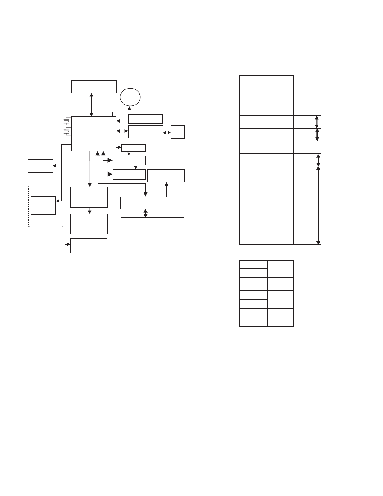
1. BLOCK DIAGRAM
The block diagram of the XE-A404/505 is shown below. The RS por t is
installed to the XE-A505 only.
FRONT DISPLAY
(2line LCD backlight)
POWER
16
32.768kHz
SD
CARD
RS Port
(SCANNER)
XE- A505
MHz
ONLY
CPU
Renesus
M30623MEP-A93GP
PRINTER DRIVER/
SENSOR
PRINTER
DRAWER IF
PR-45M
CPU
Renesus-make M30623MEP-A93GP
(Internal RAM 12KB, internal ROM 192KB)
EXTERNAL MEMORY
RAM 512KB
CYPRESS CY62148ELL-45ZSXIT
FLASH ROM 512KB
SPANSION MBM29F400TC-70PFTN
PRINTER PR45M
BUZZER
RESET IC
USB ONTROLLER
M66291GP
DECODER
4Mbit Flash ROM
4Mbit SRAM
KEY IF/POPUPDISPLAYIF
KEY
POPUP DISPLAY
(LED 7SEG)
USB
B
MODE SW
Port
2. MEMORY MAP
2-1. ADDRESS MAP
00000h SFR
Internal RAM 12KByte
00400h
(00400h-033FFh)
033FFh
03400h
04000h
Front Display
POPUP Display
08000h
External RAM
124KByte/512KByte
27000h
28000h USB Controller /CS1 32K
30000h /CS0 832K
40000h External RAM
512KByte
(256KByte x 2Bank)
80000h
External ROM
512KByte
C0000h
D0000h
FFFFFh
External RAM/CS2 area:
When RAMBANK=0, 48000h-66FFFh is shadow
40000h
48000h /CS2 area
50000h
60000h
66FFFh
67000h
70000h
7FFFFh
80000h RAMBANK=0 RAMBANK=1
00000h~ 40000h~
3FFFFh 7FFFFFh
/CS3 16K
/CS2 124K
3. CPU SETTING
3-1. OUTLINE
Model : M30623MEP-A93GP
Internal RAM : 12 KByte
Internal ROM : 192 KByte
Operation clock : 16 MHz
Sub clock : 32.768 KHz
External data bus : 8 bit
3-2. WEIGHT SETTING
CS0# (FLASH ROM and EXTERNAL SRAM) 3 BCLK
CS1# (USB CONTROLLER) 3 BCLK
CS2# (EXTERNAL SRAM IMAGE SPACE) 3 BCLK
CS3# (FRONT/POPUP DISPLAY) 2 BCLK
XE-A404/A505 HARDWARE DESCRIPTION
5 –

PC-UM10M
–
4. I/O
M16C/24 PORT MEMORY SPACE: NORMAL MODE
PROCESSOR MODE: MICRO PROCESSOR MODE
It is used by (SEPARATE BUS 8bit Width)
PIN
PORT
No.
P00 88 I /O D0 Out L P54 42 O
P01 87 I /O D1 D1 Out L P5 5 41 I
P02 86 I /O D2 D2 Out L P56 40 O ALE (NU) Out L
P03 85 I/O D3 D3 Out L P57 39 I /RDY /RDY In
P04 84 I/O D4 D4 Out L P60 38 O P60 DR1 L Out L DRAWER 1 DRIVE
P05 83 I/O D5 D5 Out L P61 37 O CLK0 FSCK(NU) L Out L FMC FSCK
P06 82 I/O D6 D6 Out L P62 36 I RXD0 FRD(NU) L Out L FMC FRD
P07 81 I/O D7 D7 Out L P63 35 O TXD0 FSD (NU) L Out L FMC FSD
P10 80 O P10 RAS L Out L RECEIPT PAPER
P11 79 O P11 RBS L Out L RECEIPT PAPER
P12 78 O P12 RCS L Out L RECEIPT PAPER
P13 77 O P13 RDS L Out L RECEIPT PAPER
P14 76 O P14 JAS L Out L JOURNAL PAPER
P15 75 O P15 JBS L Out L JOURNAL PAPER
P16 74 O P16 JCS L Out L JOURNAL PAPER
P17 73 O P17 JDS L Out L JOURNAL PAPER
P20 72 O A0 A0 Out L P74 26 O P74 /ER H Out L RS-232 /ER
P21 71 O A1 A1 Out L P75 25 I P75 /CD In RS-232 /CD
P22 70 O A2 A2 Out L P76 24 I P76 /CS In RS - 232 /CS
P23 69 O A3 A3 Out L P77 23 I P77 /DR In RS-232 /DR
P24 68 O A4 A4 Out L P80 22 O P80 BUZZER L Out L
P25 67 O A5 A5 Out L P81 21 O P81 VHCOM L In PRI NTER HEAD
P26 66 O A6 A6 Out L P82 20 I /INT 0 POFF In
P27 65 O A7 A7 Out L P83 19 I /INT1 /FRDY(NU) L Out L FMC /FRDY
P30 63 O A8 A8 Out L P84 18 O P84 /BUSY(NU) L Out L FMC #BUSY
P31 61 O A9 A9 Out L P85 17 I /NMI /NM I(NU) In
P32 60 O A10 A10 O ut L P86 11 O
P33 59 O A11 A11 Out L P87 10 I XCIN XCIN 32.768kHz
P34 58 O A12 A12 Out L P90 7 I P90 MODE In
P35 57 O A13 A13 Out L P91 6 I P91 MSENS In
P36 56 O A14 A14 Out L P92 5 O P92 BA1 L Out L BANK signal 1
P37 55 O A15 A15 Out L P93 4 O P93 BA0 L Out L BANK signal 0
P40 54 O A16 A16 Out L P94 3 O P94 DATA /CE L Out L LCD DATA LATCH
P41 53 O A17 A17 Out L P95 2 O P95 BLON L Out L BACK LIGHT ON
P42 52 O A18 A18 Out L P96 1 O P96 LCDON L Out L LCD POWER ON
P43 51 O A19 A19 Out L P97 100 I P97 IPLON In IPL ON signal
P44 50 O /CS0 /CS0 Out H P100 97 I AN0 TM In
P45 49 O /CS1 /CS1 Out L P101 95 I AN1 VPTEST In HEAD voltage
P46 48 O /CS2 /CS2 Out H P102 94 I AN2 VREF In Reference voltage
P47 47 O /CS3 /CS3 Out L P103 93
P50 46 O /WR /WR Out L P104 92 O AN4 /STRB2 H In PRINTER STORE
P51 45 O /BHE ( NU) Out L P105 91 O P105 /STRB3 H In PRINTER STORE
P52 44 O /RD /RD Out L P106 90 O P106 /S TR B4 H In PRINTER STORE
P53 43 O BCLK BCLK Out L P107 89 O P107 LATCH L In PRINTER LATCH
I/O
Pin
name
Signal
name
Initial
value
OFF
MODE
Function PORT
FEED A
FEED B
FEED C
FEED D
FEED A
FEED B
FEED C
FEED D
PIN
No.
P64 34 O /RTS1 /RS H Out L RS-232 /RS
P65 33 O P65 /FRES(NU) L Out L FMC /FRES
P66 32 I RXD1 RD In RS-232 RD
P67 31 O TXD1 SD H Out L RS-232 SD
P70 30 O TXD2 SO L Out L PRINTER DATA
P71 29 I RXD2 SI In PRINTER DATA IN
P72 28 O CLK2 PCLK L Out L PRINTER CLOCK
P73 27 O P73 DR2 L Out L DRAWER 2 DRIVE
Pin
I/O
name
/HLDA
/HOLD
XCOUT
AN3 /STRB1 H In PRINTER STORE
O
Signal
name
(NU) Out L
/HOLD In
XCOUT 32.768kHz
Initial
value
OFF
MODE
SIGNAL
OUT
SIGNAL
CONTROL
MODE KEY SENSE
MISCELLANEOUS
SENSE
signal
HEAD temperature
monitor
monitor
SIGNAL 1
SIGNAL 2
SIGNAL 3
SIGNAL 4
SIGNAL
Function
XE-A404/A505 HARDWARE DESCRIPTION
6 –
 Loading...