


WQ-284-A
SHARP
SERVICE MANUAL/SERVICE-ANLEITUNG/MANUEL DE SERVICE
SX3B3WQ284HBK
WG284H(BK)
WQm284E(BK)
W@284A(BK)
l
l
Note for users in UK
Recording and playback of any material may require consent which
SHARP is unable to give. Please refer particularly to the provisions
of Copyright Act 1956, the Dramatic and Musical
Act 1956, the Performers Protection Acts 1963 and 1972 and to any
subsequent statutory enactments and orders.
Performers
Protection
In the interests of user-safety the set should be restored to its
original condition and only parts identical tothosespecified be used.
l
Im
lnteresse der Benutzer-Sicherheit sollte dieses Gerat wiederauf
seinen
vorgeschriebenen Teile verwendet werden.
l
Dans I’int&bt de la
reconstitub dans sa condition premiere et seules des
identiques & celles
ursprtinglichen iitstand eingestellt
s&urite
de I’utilisateur, I’appareil devra
sp&ifi6es,
doivent etre
utili&es.
und nur die
A
&re
pi&es
A
IMPORTANT SERVICE NOTES (FOR UK ONLY) . . . .
SPECIFICATIONS . . . . . . . .
NAMES OF PARTS .
FITTING OF DIAL POINTER
DISASSEMBLY
REMOVING AND REINSTALLING
THE MAIN
PACKING METHOD (FOR UK ONLY) . . . . . . . . . . .
_,.,..._...,,.,_.,.......,..................................,..........
PARTS . . . . .
.._...............................................
.._.__......__..................................................
._.,.,.,..._...__..,,.................,.....,......
.._............. 1.:
. . . . . . . . . . . . . . . . . . . . . . . . . . . . . . .
0
TECHNISCHE
BEZEICHNUNG DER TEILE
ANBRINGEN
ZERLEGEN
ENTFERNEN
HAUPTTEILE ,..._...,..__..,.,,,.,..,.....,.............,............. ~ ,.......,...._.
ElNSTELLUNG
0
CARACTERISTIQUES
NOMENCLATURE . . . . . . . . . . . . . . . . . . . . . . . . . . . . . . . . . . . . . . . . . . . . . . . . . . . . . . . . . . . . . . . . . . .
FIXATIONDEL’AIGUILLE
DCMONTAGE . . . . . . . . . . . . . . . . . . . . . . . . . . . . . . . . . . . . . . . . . . . . . . . . . . . . . . . . . . . . . . . . . . . . . . . . . .
DEMONTAGE ET REMONTAGE DES
PRINCIPALES
RiGLAGE
DATEN .
DES
,.,,.._.,..,,,._,,,..........,,..........,,.,..,....,.................,......
UND
. . . . . . . . . . . . . . . . . . . . . . . . . . . . . . . . . . . . . . . . . . . . . . . . . . . . . . . . . . . . . . . . . . . .
. . . . . . . . . . . . . . . . . . . . . . . . . . . . . . . . . . . . . . . . . . . . . . . . . . . . . . . . . . . . . . . . . . . . . . . .
. . . . . . . . . . . . . . ..t.........................................................,
.._......................................................
SKALENZEIGERS
EINBAUEN
. . . . . . . . . . . . . . . . . . . . . . . . . . . . . . . . . . . . . . . . . . . . . . . . . . .
. . . . . . . . . . . . . . . . . . . . . . . . . . . . . . . . . . . .
DER
. . . . . . . . . . . . . . . . . . . . . . . . . . . . . . . . . . . . . . . . . . . . . . . . . . . . . . . . . . . .
. . . . . . . . . . . . . . . . . . . . . . . . . . . . . . . . . . . . . . . . . . . . . . . . . . . . . .
PIECES
INDEX TO CONTENTS
Page
.._.........__..
2,
4,
4, 5
6, 7
8,
..__.....................
10
2
ADJUSTMENT
3
TYPES OF TRANSISTOR . . .
SCHEMATIC DIAGRAM/WIRING
5
9
SIDE OF P.W.BOARD
NOTESONSCHEMATIC
EXPLODED
REPLACEMENT PARTS
. . . . . . . . . . . . . . . . . . . . . . . . . . . . . . . . . . . . . . . . . . . . . . . . . . . . . . . . . . . . . . . . . . . . .
VIEW . . . . . . . . . . . . . . . . . . . . . . . . . . . . . . . . . . . . . . . . . . . . . . . . . . . . . . . . . . . . . . . .
INHALTSVERZEICHNIS
Seite
2, 3
4.
4,
6, 7
8, 9 EXPLOSIONSDARSTELLUNG
11-14
TRANSISTOREN-TYPEN ,.._....,................................................ 14
5
SCHEMATISCHER
5
VERDRAHTUNGSSEITE DER LEITERPLATTE . . . . .
ANMERKUNGEN ZUM
SCHALTPLAN
ERSATZTEILLISTE . . . . . . . . ..__..................................................
TABLE DES MATICRES
Page
3
TYPES
2,
4,
4,
6,
8,
11-14
5
5
7
9
DE TRANSISTOR
DIAGRAMME
LA PLAQUETTE DE MONTAGE IMPRIMe
REMARQUES CONCERNANT LE DIAGRAMME
SCHeMATIQUE
VUE EN
LlSTE
SCHeMATIQUE/C6Tc
~CLATE ._.............,..............................................,.
DES PIECES
SCHALTPLAN/
..__.,......___............,...................................,.,........
. . . . . . . . . . . . . . . . . . . . . . . . . . . . . . . . . . . . . . . . . . . . . . . . . . . . . . . . . . .
DE
Page
1
.._......
l-l 4
15-18
20,
22-25
15-18
20,
22-25
Page
15-18
20,
22-25
14
19
21
Seite
19
21
14
19
21
..t...................................................
. . . . . . . . . . . . . . . . . . . . . . . . . . . . . . . . . . . . . . . . . . . . . . . . . . . . . . . .
DIAGRAM . . . . . . . . . . . . . . . . . . . . . . . . . . . . . . . . . . . . . . . .
LIST . . . . . . . . . . . . . . . . .._..........................
SCHEMATISCHEN
. . . . . . . . . . . . . . . . . . . . . . . . . . . . . . . . . . . . . . . . . . .
. . . . . . . . . . . . . . . . . . . . . . . . . . . . . . . . . . . . . . . . . . . . . . . . . . . . . . . . .
RECHANGE . . . . . . . . . . . . . . . . . . . . . . . . . . . . . .
CABLAGE
DE
. . . . . . . . . . . . . . . . . . . . . . .
SHARP CORPORATION
0
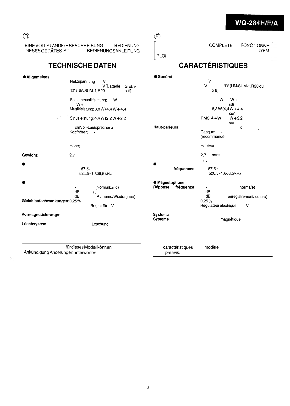
FOR A COMPLETE DESCRIPTION OF THE OPERATION OF THIS UNIT, PLEASE REFER
TO THE OPERATION MANUAL.
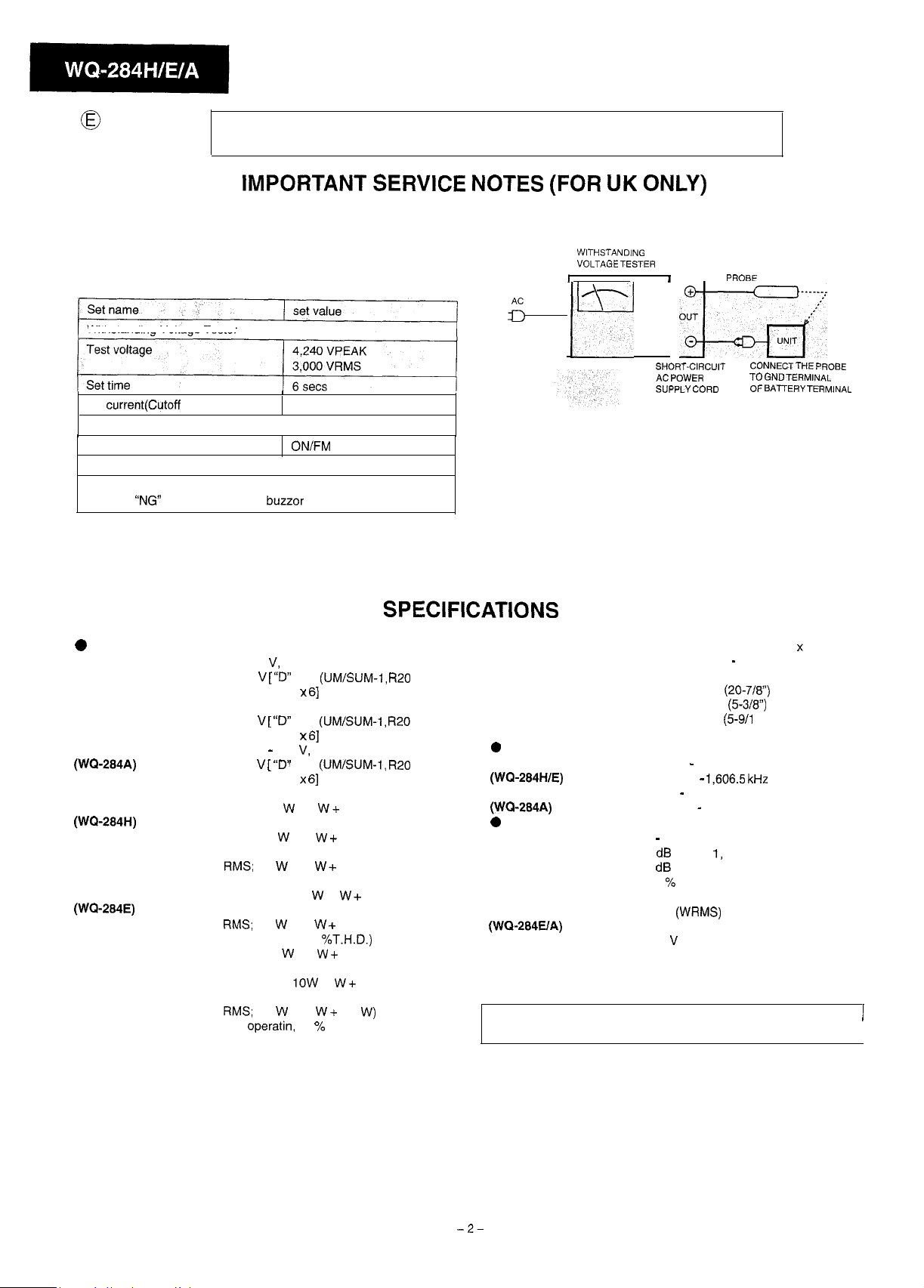
IMPORTANT SERVICE NOTES (FOR UK ONLY)
Before returning the unit to the customer after completion of a
repair or adjustment it is necessary for the following withstand
voltage test to be applied to ensure the unit is safe for the customer
to use.
Setting of Withstanding Voltage Tester and set.
Withstanding Voltage Tester
WITHSTANDING
VOLTAGE TESTER
I
;
ryl
I
oq---cJ
PROBE
Set
current(Cutoff
Unit
Power/Function
Judgment
OK: The “GOOD” lamp lights.
NG: The
0
General
Power source:
(WC?-284H)
Power source:
(WQ-284E)
Power source:
(WQ-284A)
Power consumption:
Output power:
(WQ-284H)
Output power:
(WQ-284E)
Output power:
(WQ-284A)
current)
“NG”
lamp lights and the buzzor sounds.
/
4mA
ON/FM
mono
AC 230 V, 50 Hz
DC 9 V [
HP-2) battery x
AC 240 V, 50 Hz
DC 9 V [
HP-2) battery x
AC 220 - 240 V, 50 Hz
DC 9 V [
HP-2) battery x
16W
PMPO; 28 W (14 W + 14 W)
(AC operation)
MPO; 8.8 W (4.4 W i 4.4 W)
(AC operation, DIN 45 324)
RMS;
(DC operatin, DIN 45 324)
MPO (Max.); 10 W (5 W + 5 W)
(AC operation)
RMS;
(DC operation, 10
PMPO; 28 W (14 W + 14 W)
(AC operation)
MPO (Max);
(AC operation)
RMS;
(DC operatin, 10 % T.H.D.)
“D”
size
(UMISUM-1, R20
61
“D”
size
(UM/SUM-1, R20
61
“D”
size
(UM/SUM-1, R20
61
4.4 W (2.2 W i- 2.2 W)
4.4 W (2.2 W + 2.2 W)
4.4 W (2.2 W + 2.2
%T.H.D.)
1OW
(5 W + 5 W)
w)
SPECIFICATIONS
Speakers:
Output terminal:
or
or
or
Dimensions:
Weight:
0
Radio
Frequency range:
(WQ-284HIE)
Frequency range:
(WQ-284A)
0
Tape recorder
Frequency response:
Signal/noise ratio:
Wow and flutter:
(WQ-284H)
Wow and flutter:
(WQ-284UA)
Motor:
Bias system:
Erase system:
Specifications for this model are subject to change without prior
notice.
SHORT-CIRCUIT
AC
POWER
SUPPLY
CORD
10 cm (4”) full renge speaker x 2
Headphones; 16 - 50 ohms
(recommended; 32 ohms)
Width; 530 mm
Height; 135 mm
Depth; 140 mm (5-9/l 6”)
2.7 kg (6.0 Ibs.) without batteries
FM;
87.5 - 108 MHz
AM;
526.5 -
FM;
88 - 108 MHz
AM;
526.5 - 1606.5 MHz
80 - 10,000 Hz (Normal tape)
55 dB (TAPE 1, playback)
45 dB (TAPE 2, recording/playback)
0.25 % (DIN 45 511)
0.15%
(WRMS)
DC 9 V electric governor
AC bias
Magnet erase
CONNECT THE
TO
OF
(20-7/8”)
(5-3/8”)
1,606.5 kHz
GND
TERMINAL
BATTERY TERMINAL
PROBE
I
I
-2-
EINE
VOLLSTANDIGE BESCHREIBUNG
DIESES GERATES
ENTHALTEN.
IST IN DER
TECHNISCHE DATEN
DER
BEDIENUNG
BEDIENUNGSANLEITUNG
POUR LA DESCRIPTION
MENT DE CET APPAREIL, SE REPORTER AU MODE
PLOI.
COMPLCTE
I
DU
FONCTIONNE-
CARACTERISTIQUES
D’EM-
0
Allgemeines
Spannungsversorgung:
Leistungsaufnahme:
Ausgangsleistung:
Lautsprecher:
Ausgang:
Abmessungen:
0
Radio
Frequenzbereich:
0
Cassettenrecorder
Frequenzgang:
Rauschabstand:
Gleichlaufschwankungen:0,25 %
Motor:
Vormagnetisierungs-
system:
Liischsystem:
Netzspannung 230 V, 50 Hz
Gleichspannung 9 V [Batterie in
“D” (UM/SUM-1, R20
16W
Spitzenmusikleistung; 28
(14 W + 14 W) (Netzbetrieb)
Musikleistung;
(Netzbetrieb, DIN 45 324)
Sinusleistung; 4,4 W
(Gleichspannungsbetrieb, DIN 45 324)
10 cmVoll-Lautsprecher x 2
KopfhBrer;
(empfohlen; 32 Ohm)
Breite; 530 mm
Hijhe; 135 mm
Tiefe; 140 mm
2,7
kg ohne Batterien
UKW;
MW;
80 - 10.000 Hz (Normalband)
55 dB (TAPE 1, Wiedergabe)
45 dB (TAPE 2, AufnameNViedergabe)
Elektrischer Regler
Gleichspannung
Wechselspannungsvormagnetisierung
Magnetische Lijschung
8,8 W (4,4 W +
16 - 50 Ohm
87,5 -
108 MHz
526,5 - 1.606,5
(DIN 45 511)
oder HP-2 x
W
4,4 W)
(2,2 W + 2,2
kHz
fiir
9
V
GrijRe
61
W)
0 G&&al
Alimentation:
Consommation:
Puissance de sortie:
Haut-parleurs:
Borne de sortie:
Dimensions:
Poids:
0
Radio
Gamme de frkquences:
0
Magn&ophone
RBponse
Rapport signal/bruit:
Pleurage et scintillement:
Moteur:
Systi?me
Systeme
en frequence:
de polarisation:
d’effacement:
230 V CA, 50 Hz
9 V CC [Pile
HP-2) x
16W
PMPO; 28 W (14 W + 14 W)
(fonctionnement
MPO; 8,8 W
(fonctionnement
RMS; 434 W
(fonctionnement
Large bande de 10 cm x 2
Casque; 16 - 50 ohms
(recommandb; 32 ohms)
Largeur; 530 mm
Hauteur; 135 mm
Profondeur; 140 mm
2,7
kg sans piles
(*
FM;
87,5 -
PO; 526,5 -
80 - 10.000 Hz (Bande normale)
55 dB (TAPE 1, lecture)
45 dB (TAPE 2, enregistrement/lecture)
0,25 % (DIN 45 511)
FiBgulateur
cc
Polarisation CA
Effacement magnbtique
“D” (UM/SUM-1, R20
61
sur
CA)
(4,4 W +
4,4 W)
sur
CA, DIN 45 324)
(2.2 W +
sur
CC, DIN 45 324)
108 MHz
1.606,5 kHz
electrique de 9
2,2
ou
W)
~
V
Dietechnischen Daten
Anktindigung Anderungen unterworfen
fijrdieses
Model1
kijnnen
sein.
ohne vorherige
Les
caract&istiques
sans
prbavis.
de ce
mod&le
sont sujettes &modification
-3-
0
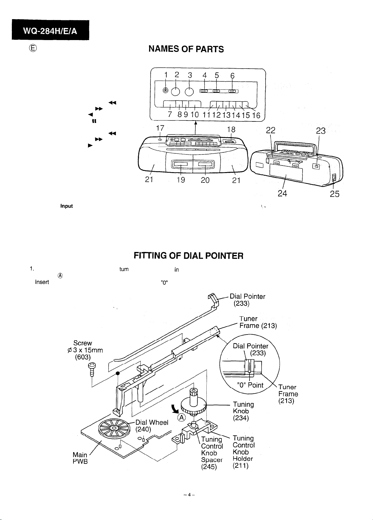
1. Headphones Socket
2. Volume Control
3. Tone Control
4. Dubbing Speed/Built-in Microphone Switch
5. Function Selector/FM Mode Swicth
6. Band Selector Switch
7. (TAPE 1) Stop/Eject Button:
8. (TAPE 1) Fast Forward Button:
9. (TAPE 1) Rewind Button:
10. (TAPE 1) Play Button:
11. (TAPE 2) Pause Button:
12. (TAPE 2) Stop/Eject Button:
13. (TAPE 2) Fast Forward Button:
14. (TAPE 2) Rewind Button:
15. (TAPE 2) Play Button:
16. (TAPE 2) Record Button:
17. Built-in Microphone
18. Tuning Control
19. (TAPE 1) Cassette Compartment
20. (TAPE 2) Cassette Compartment
21. Full Range Speaker
22. FM Telescopic Rod Aerial
23. Beat Cancel Switch
24. Battery Compartment
25. AC Power Input Socket
n
t(
m
+
II
n
qq
w
)
l
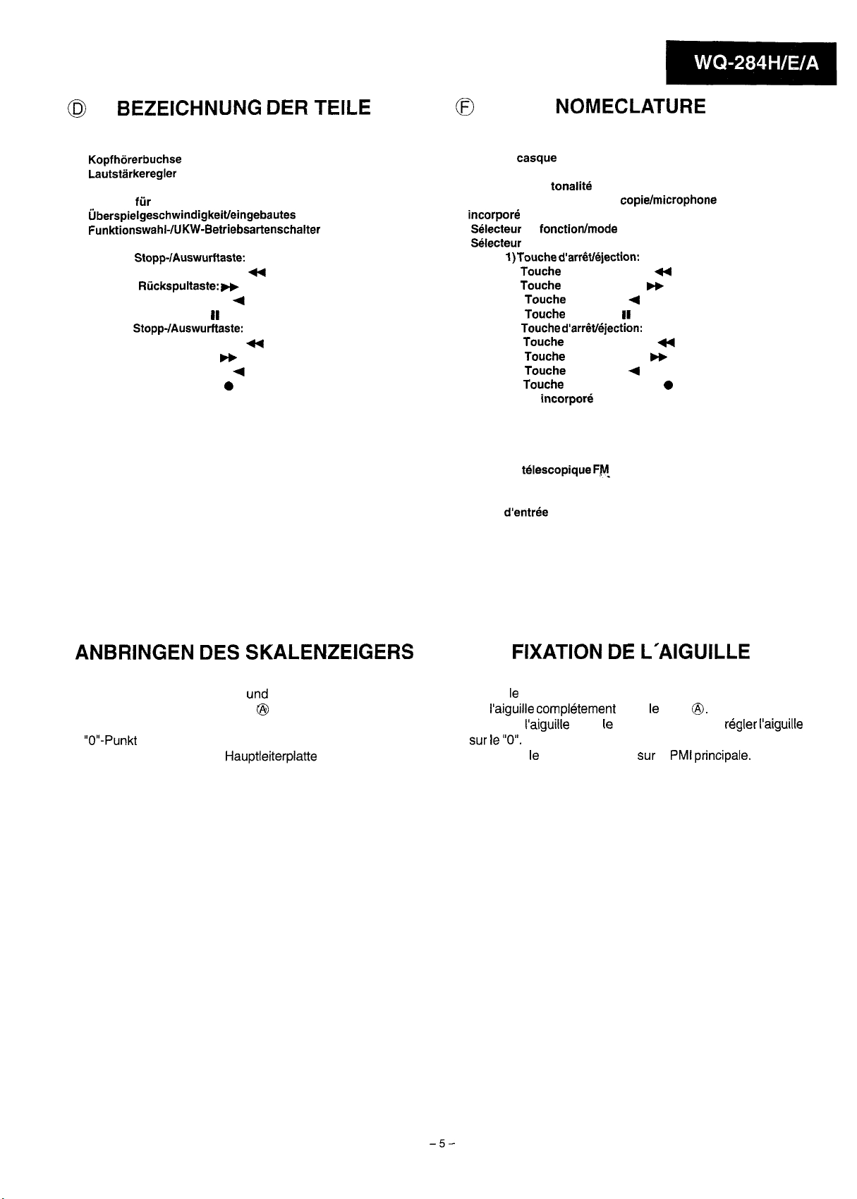
NAMES OF PARTS
FITTING OF DIAL POINTER
1.
Remove the tuner frame, and then
direction @ as for as it will go.
2. Insert the dial pointer into the tuner frame and fix the
3. Mount the tuner frame on the main PWB.
turn
the dial drum gear
“0”
in
point.
Figure 4
0
BEZEICHNUNG DER TEILE
0
NOMECLATURE
1.
Kopfhorerbuchse
2. Lautstlrkeregler
3. Klangfarbenregler
4. Schalter fur
Uberspielgeschwindigkeitleingebautes Mikrofon
5. Funktionswahl-IUKW-Betriebsartenschalter
6. Wellenbereichswahlschalter
7. (TAPE 1) Stopp-/Auswurftaste:
8. (TAPE 1) Schnellvorlauftaste:
9. (TAPE 1) Riickspultaste:
10. (TAPE 1) Wiedergabetaste:
11. (TAPE 2) Pausentaste:
12. (TAPE 2) Stopp-/Auswurftaste:
13. (TAPE 2) Schnellvorlauftaste:
14. (TAPE 2) Riickspultaste:
15. (TAPE 2) Wiedergabetaste:
16. (TAPE 2) Aufnahmetaste:
17. Eingebautes Mikrofon
18. Abstimmregler
19. (TAPE 1) Cassettenfach
20. (TAPE 2) Cassettenfach
21. Breitband-Lautsprecher
22. UKW-Teleskopantenne
23. Schwebungsunterdriickungsschaiter
24. Batteriefach
25. Netzeingangsbuchse
n
+
w
(
II
n
t(
w
+
0
1. Prise de casque
2. Commande de volume
3. Commande de tonalite
4. Commutateur de vitesse de copie/microphone
incorpore
5. Selecteur de fonction/mode FM
6. Selecteur de gamme d’ondes
7. (TAPE 1) Touche d’arr&/ejection:
8. (TAPE 1) Touche d’avance rapide:
9. (TAPE 1) Touche de rebobinage:
10. (TAPE 1) Touche de lecture:
11. (TAPE 2) Touche de pause:
12. (TAPE 2) Touche d’arrevejection:
13.
(TAPE 2) Touche d’avance rapide:
14. (TAPE 2) Touche de rebobinage:
15. (TAPE 2) Touche de lecture:
16.
(TAPE 2) Touche d’enregistrement:
17.
Microphone incorpore
18.
Commande d’accord
19. (TAPE 1) Compartiment de cassette
20. (TAPE 2) Compartiment de cassette
21. Haut-parleur de large bande
22. Antenne telescopique
23.
Commutateur antibattement
24. Logement de piles
25. Prise
d’entree
secteur
FM-
n
H
m
(
II
n
4
b+
+
0
ANBRINGEN DES SKALENZEIGERS
1. Den Tunerrahmen entfernen,
Skalentrommelrad in Fiichtung @ ganz drehen.
2. Den Skalenzeiger in den Tunerrahman einsetzen und den
“O”-Punkt
Befestigen.
3. Den Tunerrahmen an der Hauptleiterplatte anbringen.
und
danach das
FIXATION DE L’AIGUILLE
1. Retirer le Chassis de tuner et tourner I’engrenage de tambour
de i’aiguille completement dans le sens
2. lntroduire I’aiguille dans le chassis de tuner et regler
sur le “0”.
3. Remonter le chassis de tuner
sur
0,.
la
PMt principale.
I’aiguille
-5-
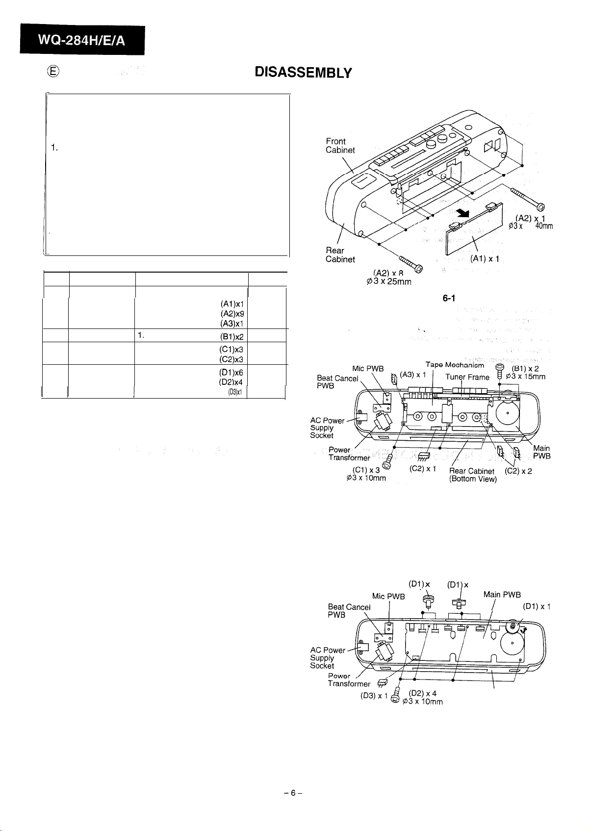
DISASSEMBLY
Caution on Disassembly
Follow the below-mentioned notes when disassembling the
unit and reassembling it, to keep its safety and excellent
performance:
Take cassette tape out of the unit.
1.
Be sure to remove the power supply plug from the wall
2.
outlet before starting to disassemble the unit and remove
the batteries from the unit.
Take off nylon bands or wire holders where they need be
3.
removed when disassembling the unit. After servicing the
unit, be sure to rearrange the leads where they were
before disassembling.
4. Take sufficient care on static electricity of integrated
circuits and other circuits when servicing.
@3x
40mm
STEP REMOVAL
1
Front Cabinet
2
Tuner Frame
3
Tape Mechanism
4
Main PWB
1. Battery
Compartment
2.
Screw
3.
Socket
1.
Screw
1.
Screw
2.
Socket
1.
Knob
2.
Screw
1
3.
Socket
PROCEDURE
lid.
.....
......................
.....................
......................
......................
.....................
.......................
......................
. . . . . . . . . . . . . . . . . . . . .
(Al)xl
@2)x9
(A3)xl
(Bl)x2
(Cl)x3
(C2)x3
(Dl)x6
(D2)x4
FIGURE
(DSjxl
6-l
6-2
6-2
6-2
6-3
a3
x
i5mm
Figure
6-1
Figure 6-2
-6-
MirPlAIR
(Di,)
x 2
@
Figure 6-3
(Dl) x
4
3
Ma/nPWB(Dl)x,
Rear Cabinet
,
 Loading...