


WQ-730-H
WQ-730H
– 1 –
SERVICE MANUAL/SERVICE-ANLEITUNG/MANUEL DE SERVICE
WQ-730H(BK)
• In the interests of user-safety the set should be restored to its
original condition and only parts identical to those specified
should be used.
• Im Interesse der Benutzer-Sicherheit sollte dieses Gerät wieder
auf seinen ursprünglichen Zustand eingestellt und nur die
vorgeschriebenen Teile verwendet werden.
• Dans l’intérêt de la sécurité de l’utilisateur, l’appareil devra être
reconstitué dans sa condition première et seules des pièces
identiques à celles spécifiées, doivent être utilisées.
CONTENTS
Page
NOTES ON SCHEMATIC DIAGRAM ......................... 11
SCHEMATIC DIAGRAM / WIRING
SIDE OF P.W.BOARD ............................................... 12
PACKING METHOD (FOR UK ONLY)........................ 16
REPLACEMENT PARTS LIST/EXPLODED VIEW
Page
IMPORTANT SERVICE NOTES (FOR UK ONLY) ....... 2
SPECIFICATIONS ........................................................ 2
NAMES OF PARTS ...................................................... 4
FITTING OF DIAL POINTER ........................................ 4
DISASSEMBLY............................................................. 6
ADJUSTMENT .............................................................. 8
INHALTSVERZEICHNIS
Seite
TECHNISCHE DATEN.................................................. 2
BEZEICHNUNG DER TEILE ........................................ 4
ANBRINGEN DES SKALENZEIGERS ......................... 4
ZERLEGEN................................................................... 6
EINSTELLUNG ............................................................. 8
Seite
ANMERKUNGEN ZUM SCHEMATISCHEN
SCHALTPLAN............................................................ 11
SCHEMATISCHER SCHALTPLAN/
VERDRAHTUNGSSEITE DER LEITERPLATTE....... 12
ERSATZTEILLISTE /EXPLOSIONSDARSTELLUNG
TABLE DES MATIÈRES
Page
REMARQUES CONCERNANT LE DIAGRAMME
SCHÉMATIQUE......................................................... 11
DIAGRAMME SCHÉMATIQUE/CÔTÉ CÂBLAGE DE
LA PLAQUETTE DE MONTAGE IMPRIMÉ............... 12
LISTE DES PIÈCES DE RECHANGE /VUE EN ÉCLATE
Page
CARACTÉRISTIQUES.................................................. 2
NOMENCLATURE ........................................................ 4
FIXATION DE L’AIGUILLE ........................................... 4
DÉMONTAGE ............................................................... 6
RÉGLAGE..................................................................... 8
E
D
F
No. SX672WQ730HBK
SHARP CORPORATION
WQ-730H
– 2 –
FOR A COMPLETE DESCRIPTION OF THE OPERATION OF THIS UNIT, PLEASE REFER
TO THE OPERATION MANUAL.
E
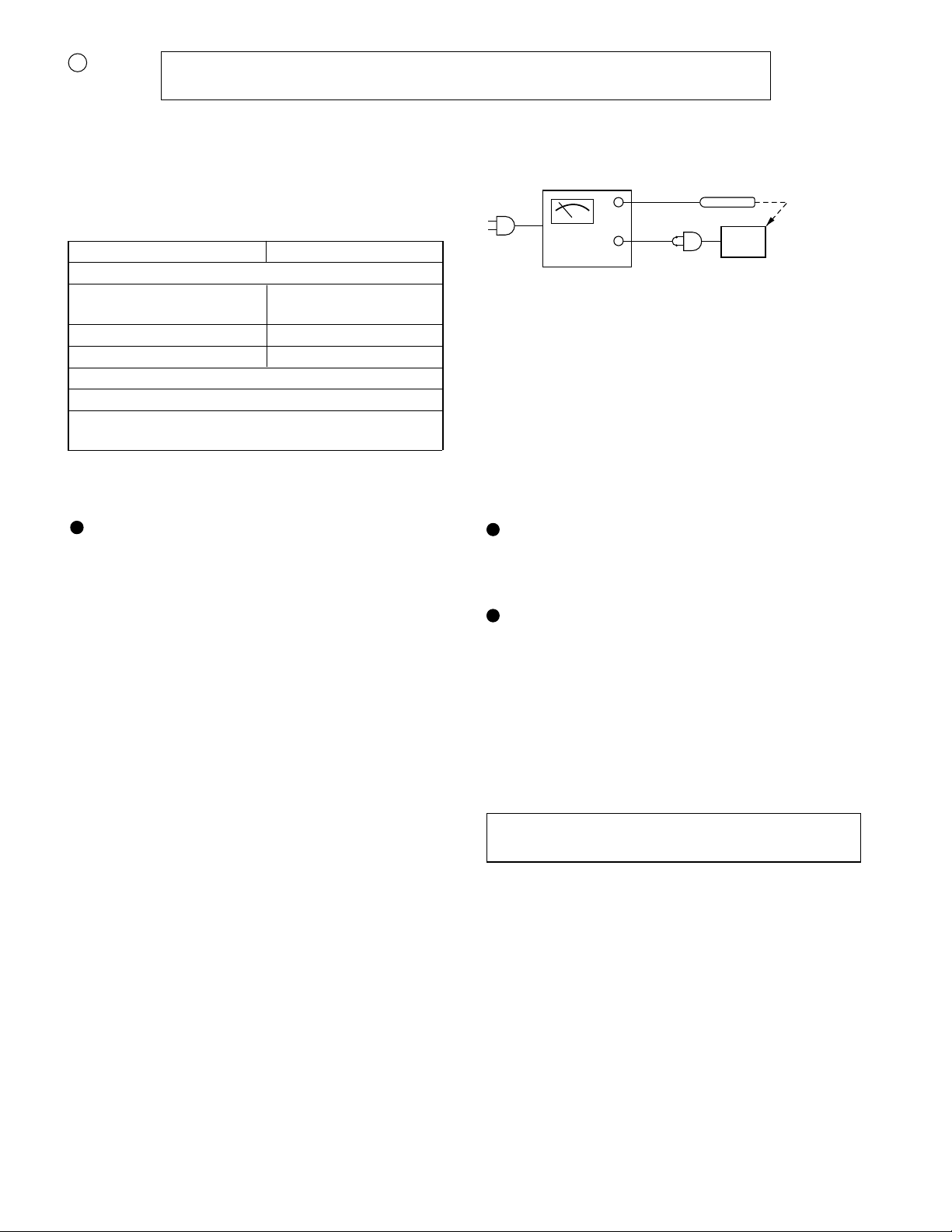
OUT
WITHSTANDING
VOLTAGE TESTER
SHORT-CIRCUIT
AC POWER
SUPPLY CORD
CONNECT THE PROBE
TO GND OF BATTERY
TERMINAL
+
–
AC
UNIT
PROBE
IMPORTANT SERVICE NOTES (FOR UK ONLY)
SPECIFICATIONS
General
Power source: AC 220-230 V, 50 Hz
DC 12 V ["D" size (UM/SUM-1,R20
or HP-2) battery x 8]
Power consumption: 30 W
Output power: PMPO; 60 W (30 W + 30 W)
(AC operation)
MPO (Max.); 20 W (10W + 10 W)
(AC operation)
RMS; 10 W (5 W + 5 W)
(DC operation, DIN 45 324)
Speakers: 12 cm (4-3/4") free-edge
woofer x 2
5 cm (2") surround speaker x 2
Optput terminal: Headphones; 16-50 ohms
(recommended; 32 ohms)
Dimensions: Widh; 600 mm (23-5/8")
Height; 195 mm (7-11/16")
Depth; 190 mm (7-1/2")
Weight: 4.3 kg (9.5 lbs.) without batteries
Radio section
Frequency range: FM; 87.5 - 108 MHz
MW; 526.5 - 1,606.5 kHz
LW; 148.5 - 283.5 kHz
Tape recoder section
Frequency rasponse: 60 - 12,000 Hz (Normal tape)
Signal/noise rario: 40 dB (TAPE 1, recording/
playback)
55 dB (TAPE 2, playback)
Wow and flutter: 0.15 % (DIN 45 511)
Motor: DC 12 V electric governor
Bias system: AC bias
Erase system: Magnet earse
Specifications for this model are subject to change without
prior notice.
Before returning the unit to the customer after completion of
a repair or adjustment it is necessary for the following with-
stand voltage test to be applied to ensure the unit is safe for
the customer to use.
Setting of Withstanding Voltage Tester and set.
Set name set value
Withstanding Voltage Tester
Test voltage 4,240 VPEAK
3,000 VRMS
Set time 6 secs
Set current(Cutoff current) 4 mA
Unit
Judgment
OK: The “GOOD” lamp lights.
NG: The “NG” lamp lights and the buzzor sounds.

WQ-730H
– 3 –
D
F
POUR LA DESCRIPTION COMPLÉTE DU FONCTION-
NEMENT DE CET APPAREIL, SE REPORTER AU MODE
D'EMPLOI.
EINE VOLLSTÄNDIGE BESCHREIBUNG DER BEDIE-
NUNG DIESES GERÄTES IST IN DER BEDIENUNGS-
ANLEITUNG ENTHALTEN.
TECHNISCHE DATEN CARACTÉRISTIQUES
Allgemeines
Spannungsversorgung: Netzspannung 220-230 V, 50 Hz
Gleichspannung 12 V [Batterie in
Größe "D" (UM/SUM-1,R20 oder
HP-2) x 8]
Leistungsaufnahme: 30 W
Ausgangsleistung: Spitzenmusikleistung; 60 W
(30 W + 30 W) (Netzbetrieb)
Musikleistung (max.); 20 W
(10W + 10 W) (Netzbetrieb)
Sinusleistung; 10 W (5 W + 5 W)
(Gleichspannungsbetrieb, DIN 45
324)
Lautsprecher: Randloser 12 cm-Tieftöner x 2
5 cm Surround-Lautsprecher x 2
Ausgang: Kopfhörer; 16-50 Ohm
(empfohlen; 32 Ohm)
Abmessungen: Breite; 600 mm
Höhe; 195 mm
Tiefe; 190 mm
Gewicht: 4,3 kg ohne Batterien
Radio-Teil
Frequenzbereich: UKW; 87,5 - 108 MHz
MW; 526,5 - 1.606,5 kHz
LW; 148,5 - 283,5 kHz
Tonbandrecorder-Teil
Frequenzgang: 60 - 12.000 Hz (Normalband)
Rauschabstand: 40 dB (TAPE 1, Aufnahme/
Wiedergabe)
55 dB (TAPE 2, Wiedergabe)
Gleichlauf-
schwankungen: 0,15 % (DIN 45 511)
Motor: Elektrischer Regler für 12 V
Gleichspannung
Vormagnetisierungs-
system: Wechselspannungsvormagneti-
sierung
Löschsystem: Magnetische Löschung
Général
Alimentation: 220-230 V CA, 50 Hz
12 V CC [Pile "D" (UM/SUM-1,R20
ou HP-2) x 8]
Consommation: 30 W
Puissance de sortie: PMPO; 60 W (30 W + 30 W)
(fonctionnement sur CA)
MPO (maxi); 20 W (10W + 10 W)
(fonctionnement sur CA)
RMS; 10 W (5 W + 5 W)
(fonctionnement sur CC, DIN 45
324)
Haut-parleurs: Woofer à bords libres de 12 cm x 2
Haut-parleur surround de 5 cm x 2
Borne de sortie: Casque; 16-50 ohms
(recommandé; 32 ohms)
Dimensions: Largeur; 600 mm
Hauteur; 195 mm
Profondeur; 190 mm
Poids: 4,3 kg sans piles
Radio
Gamme de fréquences: FM; 87,5 - 108 MHz
PO; 526,5 - 1.606,5 kHz
GO; 148,5 - 283,5 kHz
Magnétophone à cassette
Réponse en fréquence: 60 - 12.000 Hz (Bande normale)
Rapport signal/bruit: 40 dB (TAPE 1, enregistrement/
lecture)
55 dB (TAPE 2, lecture)
Pleurage et
scintillement: 0,15 % (DIN 45 511)
Moteur: Régulateur électrique de 12 V CC
Système de
polarisation: Polarisation CA
Système d'effacement: Effacement magnétique
Dietechnischen Daten für dieses Modell können ohne
vorherige Ankündigung Änderungen unterworfen sein.
Les caractéristiques de ce modèle sont sujettes à modifi-
cation sans préavis.
WQ-730H
– 4 –
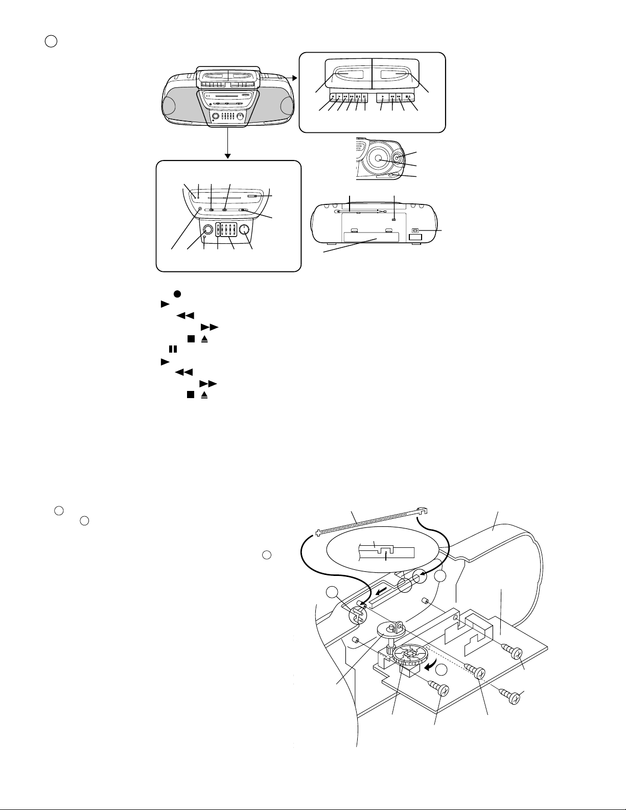
NAMES OF PARTS
E
14 16
2120 2219 2423
2 3 4 5 6 7 8 9 10 11
12
25
1
17
18
13 15
26
27
28
29
30
31
1. (TAPE 1) Cassette Compartment
2. (TAPE 1) Record Button:
3. (TAPE 1) Play Button:
4. (TAPE 1) Rewind Button:
5. (TAPE 1) Fast Forward Button:
6. (TAPE 1) Stop/Eject Button:
7. (TAPE 1) Pause Button:
8. (TAPE 2) Play Button:
9. (TAPE 2) Rewind Button:
10. (TAPE 2) Fast Forward Button:
11. (TAPE 2) Stop/Eject Button:
12. (TAPE 2) Cassette Compartment
13. Power Indicator
14. FM Stereo Indicator
15. Dubbing Speed/Built-in Microphone/FM Mode
Switch
16. Function Selector Switch
17. Tuning Control
18. Band Selector Switch
19. Headphone Socket
20. Surround Switch
21. Built-in Microphone
22. Extra Bass Control: X-BASS
23. Graphic Equalizer Controls
24. Volume Control
25. Surround Speaker
26. Woofer
27. Bass Reflex Duct
28. FM/SW Telescopic Rod Arial
29. Beat Cancel Switch
30. AC Power Input Socket
31. Battery Compartment
1. Remove the main PWB. Attach the dial pointer as shown arrow
A on the front cabinet, putting it into the section indicated by
arrow .
2. Install the main PWB in the front cabinet and secure it with the
four screws.
3. Turn the dial drum in the direction indicated by arrow . Set
the dial pointer to point "0", and then make the rest of the
adjustments.
A
B
C
Front Cabinet
Dial Drum
(220)
Screw(609)
ø3 x8mm
Screw(609)
ø3 x8mm
Screw(608)
ø2.6 x8mm
Main PWB
Dial Pointer (221)
Dial Pointer (221)
''0''Point
B
C
A
Tuning
Control
Knob (223)
Figure 4
FITTING OF DIAL POINTER
/
/

WQ-730H
– 5 –
D
F
NOMECLATURE
BEZEICHNUNG DER TEILE
1. (TAPE 1) Compartiment de cassette
2. (TAPE 1) Touche d'enregistrement:
3. (TAPE 1) Touche de lecture:
4. (TAPE 1) Touche de rebobinage:
5. (TAPE 1) Touche d'avance rapide:
6. (TAPE 1) Touche d'arrêt/éjection:
7. (TAPE 1) Touche de pause:
8. (TAPE 2) Touche de lecture:
9. (TAPE 2) Touche de rebobinage:
10. (TAPE 2) Touche d'avance rapide:
11. (TAPE 2) Touche d'arrêt/éjection:
12. (TAPE 2) Compartiment de cassette
13. Voyant d'alimentation
14. Voyant de FM stéréo
15. Commutateur de vitesse de copie/microphone
incorporé/mode FM
16. Sélecteur de fonction
17. Commande d'accord
18. Sélecteur de gamme d'ondes
19. Prise de caque
20. Commuteur surround
21. Microphone incorporé
22. Commande des extra-graves: X-BASS
23. Commandes de l'égaliseur graphique
24. Commande de volume
25. Enceinte surround
26. Woofer
27. Évent de baffle réflex
28. Antenne télescopique FM/OC
29. Commutateur antibattement
30. Prise d'entrée secteur
31. Logement de piles
1. (TAPE 1) Cassettenfach
2. (TAPE 1) Aufnahmetaste:
3. (TAPE 1) Wiedergabetaste:
4. (TAPE 1) Rückspultaste:
5. (TAPE 1) Schnellvorlauftaste:
6. (TAPE 1) Stopp-/Auswurftaste:
7. (TAPE 1) Pausentaste:
8. (TAPE 2) Wiedergabetaste:
9. (TAPE 2) Rückspultaste:
10. (TAPE 2) Schnellvorlauftaste:
11. (TAPE 2) Stopp-/Auswurftaste:
12. (TAPE 2) Cassettenfach
13. Einschaltanzeige
14. UKW-Stereoanzeige
15. Schalter für Überspielgeschwindigkeit/Eingebautes
Mikrofon/UKW-Betriebsart
16. Funktionswahlschalter
17. Abstimmregler
18. Wellenbereichswahlschalter
19. Kopfhörerbuchse
20. Sorround-Schalter
21. Eingebautes Mikrofon
22. Extratieftonregler: X-BASS
23. Regler des graphischen Equalizers
24. Lautstärkeregler
25. Surround-Lautsprecher
26. Tieftöner
27. Baßreflexkanal
28. UKW/KW-Teleskopantenne
29. Schwebungsunterdrückungsschalter
30. Netzeingangsbuchse
31. Batterifach
/
/
/
/
ANBRINGEN
DES SKALENZEIGERS
FIXATION DE L´AIGUILLE
1. Retirer la PMI principale. Attacher l’index au coffret frontal
comme l’indique la flèche , en l’introduisant dans la partie
indiquée par les flèches .
2. Mettre la PMI principale dans le coffret frontal et fixer la PMI
avec deux vis.
3. Tourner le tambour de cadran dans le sens indiqué par la
flèche . Régler l’index sur le point “0” et puis effectuer les
autres ajustements.
1. Die Hauptleiterplatte entfernen. Den Skalenzeiger wie
durch Pfeil gezeigt an den Gehäusevorderteil anbrin-
gen, indem er in den durch Pfeil angezeigten Teil gesetzt
wird.
2. Die Hauptleiterplatte in den Gehäusevorderteil einbauen
und mit zwei Schrauben sichern.
3. Die Skalentrommel in Pfeilrichtung drehen. Den Skalen-
zeiger auf “0” stellen, und dann sonstige Einstellungen
durchführen.
B
A
C
A
B
C

WQ-730H
– 6 –
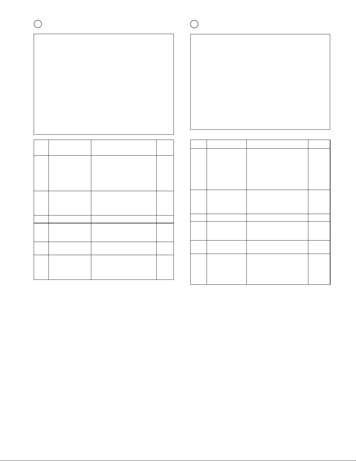
DISASSEMBLY
Caution on Disassembly
Follow the below-mentioned notes when disassembling
the unit and reassembling it, to keep it safe and ensure
excellent performance:
1. Take cassette tape out of the unit.
2. Be sure to remove the power supply plug from the wall
outlet before starting to disassemble the unit and remove
the batteries from the unit.
3. Take off nylon bands or wire holders where they need
be removed when disassembling the unit. After servicing
the unit, be sure to rearrange the leads where they were
before disassembling.
4. Take sufficient care on static electricity of integrated
circuits and other circuits when servicing.
STEP REMOVAL PROCEDURE FIGURE
1 Front Cabinet/ 1. Battery Compartment .....
Rear Cabinet Lid........................(A1)x1 6-1
2. Screw ................... (A2)x6
3. Screw ................... (A3)x2
4. Screw ................... (A4)x1
5. Socket .................. (A5)x1
6. Tip ........................(A6)x1
2 Tape Mechanism 1. Socket .................. (B1)x3 6-2
2. Screw ................... (B2)x2
3. Open the cassette holder.
4. Screw ................... (B3)x6
3 LED PWB 1. Socket ..................(C1)x1 6-3
4 Main PWB 1. Socket ..................(D1)x5 6-3
2. Screw ...................(D2)x3
3. Screw ...................(D3)x1
5 Surround PWB/ 1. Screw ................... (E1)x1 6-4
LED PWB 2. Bracket .................(E2)x2
6 Graphic Equalizer 1. Knob..................... (F1)x1 6-4
PWB 2. Knob holder.......... (F2)x1
3. Screw ................... (F3)x4
4. Shield Paper ........ (F4)x1
Figure 6-3
Figure 6-1
Main
PWB
(A5) x1
(A2) x6
ø3 x20mm
(A3) x2
ø3 x12mm
(A4) x1
ø3 x10mm
(A1) x1
Front Cabinet
Rear Cabinet
Main
PWB
(A6) x1
Figure 6-2
Figure 6-4
(E1) x1
ø3 x8mm
(F3) x4
ø3 x10mm
(F2) x1
(F1) x1
(F4) x1
Front Cabinet
LED PWB
Graphic
Equalizer
PWB
Surround
PWB
(E2) x1
(D3) x1
ø2.6 x8mm
(D1) x4
(D1) x1
(C1) x1
(D2) x3
ø3 x8mm
Front Cabinet
Main
PWB
Hook
LED PWB
(B2) x1
ø3 x10mm
(B2) x1
ø3 x10mm
(B3) x6
ø3 x10mm
Main
PWB
(B1) x2
(B1) x1
Front Cabinet
Tape
Mechanism
Cassette Holder
(Left/Right)
Open
Open
E
WQ-730H
– 7 –
1 Coffret arrière/ 1. Couvercle de logement
Coffret avant de piles.............. (A1)x1 6-1
2. Vis ......................(A2)x6
3. Vis ......................(A3)x2
4. Vis ......................(A4)x1
5. Douille ................ (A5)x1
6. Bout ....................(A6)x1
2 Mécanisme 1. Douille ................ (B1)x3 6-2
casstte 2. Vis ......................(B2)x2
3. Ouvrir le porte-cassette.
4. Vis ......................(B3)x6
3 PMI de LED 1. Douille ................ (C1)x1 6-3
4 PMI principale 1. Douille ................ (D1)x5 6-3
2. Vis ......................(D2)x3
3. Vis ......................(D3)x1
5 PMI surround/ 1. Vis ......................(E1)x1 6-4
PMI de LED 2. Support............... (E2)x2
6 PMI de l'egaliseur 1. Bouton................(F1)x1 6-4
graphique 2. Porte-bouton ...... (F2)x1
3. Vis ......................(F3)x4
4. Papier de
blindage ............ (F4)x1
1 Gehäusehintertei/ 1. Batteriefachdeckel.. (A1)x1 6-1
Gehäusevorderteil 2. Schraube ................ (A2)x6
3. Schraube ................(A3)x2
4. Schraube ................(A4)x1
5. Buchse.................... (A5)x1
6. Spitze ......................(A6)x1
2 Band 1. Buchse.................... (B1)x3 6-2
mechanismus 2. Schraube ................(B2)x2
3. Das Cassettenfach öffnen.
4. Schraube ................(B3)x6
3 LED-Leiterplatte 1. Buchse....................(C1)x1 6-3
4 Hauptleitplatte 1. Buchse....................(D1)x5 6-3
2. Schraube ................(D2)x3
3. Schraube ................(D3)x1
5 Surroundplatte/ 1. Schraube ................(E1)x1 6-4
LED-Leiterplatte 2. Halterung ................(E2)x2
6 Frequenzgangent- 1. Knopf.......................(F1)x1 6-4
Zerrer-Leiterplatte 2. Knopfhalter .............(F2)x1
3. Schraube ................(F3)x4
4. Abschirmpapier ......(F4)x1
D
F
DÉMONTAGEZERLEGEN
Vorsichtsmaßregeln für das Zerlegen
Beim Zerlegen und Zusammenbauen des Gerätes die
folgenden Anweisungen befolgen, um dessen
Betriebssicherheit und ausgezeichnete Leistung
aufrechtzuerhalten.
1. Cassettenband aus dem Gerät herausnehmen.
2. Bevor mit dem Zerlegen des Gerätes begonnen wird,
unbedingt den Netzstecker aus der Wandsteckdose
ziehen und die Batterien aus dem Gerät entfernen.
3. Nylonbänder oder Leitungshalter entfernen, falls dies
beim Zerlegen des Gerätes erforderlich ist. Nach Warten
des Gerätes darauf achten, die Leitungen wieder so zu
verlegen, wie sie vor den Zerlegen angeordnet waren.
4. Beim Warten auf statische Elektrizität der integrierten
Schaltkreise und andere Schaltungen achten.
Précautions pour le démontage
Lors du démontage de l’appareil et de son remontage,
suivre les précautions ci-dessous, pour maintenir la sécurité
et d’excellentes performances.
1. Enlever la cassette de l’unité.
2. S’assurer de retirer la fiche d’alimentation secteur de la
prise murale avant de démarrer le démontage de
l’appareil et déposer les piles de l’appareil.
3. Déposer les bandes de nylon ou les serre-câbles si
nécessaire lors du démontage de l’appareil. Après la
réparation de l’appareil, s’assurer de redisposer les fils
tel qu’ils étaient avant le démontage.
4. Faire attention à l’électricité statique des circuits intégrés
et des autres circuits lors de la réparation.
ÉTAPE
DÉPOSE PROCÉDÉ
FIGURE
ABBIL-
DUNG
SCH-
RITT
ENTFERNEN
VERFAHREN
WQ-730H
– 8 –
IF T3
MW Band fL: L6
Coverage fH: TC8
MW Tracking fL (600 kHz): L3 (MW)
fH (1,400 kHz): TC7
LW Band fL: L7
Coverage fH: TC4
LW Tracking fL (170 kHz): L4 (LW)
fH (270 kHz): TC2
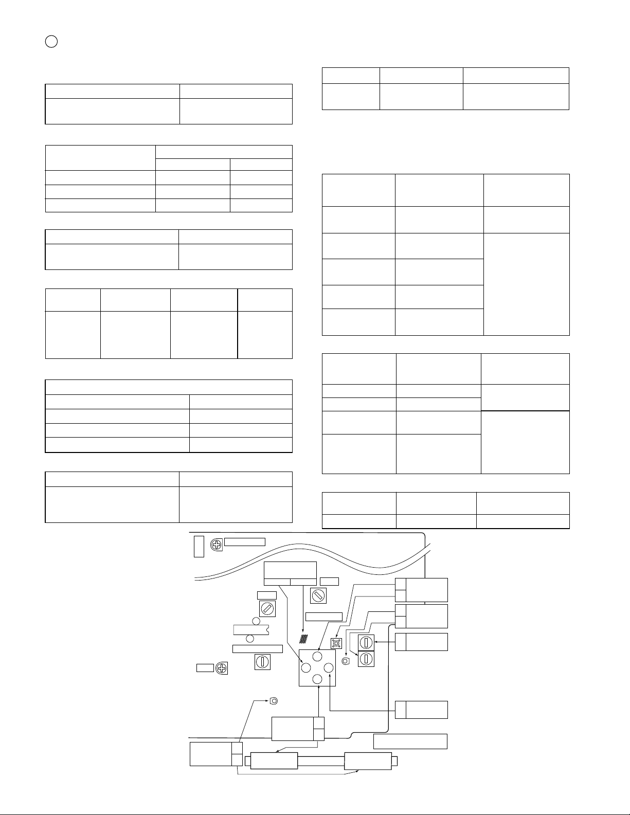
ADJUSTMENT
E
Specified Value
Test Tape
• Playback Amplifier Sensitivity Check
Instrument Connection
MTT-118 1.3 V ± 3 dB Speaker terminal
(Load resistance: 3 ohms)
MECHANISM SECTION
• Driving Force Check
Play: TW-2412 Tape 1: Over 50g
Tape 2: Over 60 g
Torque Meter
Specified Value
• Torque Check
Figure 8 ADJUSTMENT POINTS
Specified Value
Torque Meter
Tape 1 Tape 2
Play: TW-2111 30 to 60 g.cm 30 to 60 g.cm
Fast forward: TW-2231 55 to 120 g.cm 80 to 135 g.cm
Rewind: TW-2231 55 to 120 g.cm 80 to 135 g.cm
MTT-114 Headphones Socket
(Load resistance: 32 ohms)
Test Tape
Instrument Connection
• Head Azimuth
Test Tape
• Tape Speed (Normal only)
Adjusting
Point
Specified
Value
Instrument
Connection
MTT-111 Tape 1,2: VR501 3,000 ± 60 Hz Headphones
socket(Load
resistance:
32 ohms)
TAPE SECTION
Volume control Max
Beat cancel A
Function/Power Tape/Stand-by
Dubbing speed/Built-in Microphone Normal/Mic Off
Position of each switch or control
• Bias Oscillation Frequency
Beat cancel A: 100 ± 4 kHz
B: 94 ± 4 kHz
C: 104 ± 4 kHz
Specified Value
TUNER SECTION
fL: Low-range frequency
fH: High-range frequency
• AM IF/RF
Specified
Value/Adjusting
Point
Test Stage
Instrument
Connection
Input: Antenna
Output: Pin 3 of IC2
Input: Antenna
Output: Headphones
Socket
(Load resistance:
32 ohms)
MAIN PWB
FM
TRACKING
fLfH
FM BAND
COVERAGE
fL
fH
LW BAND
COVERAGE
fL
fH
LW
TRACKING
fL
fH
VR1
VR501
CNP501
13 24
12 1
VCO
T2
L2
L1
IC1
T1
T3
TC7
TC6
TC8
TC4
L7
L6
TC5
TC2
MW BAND
COVERAGE
fH
MW BAND
COVERAGE
fL
IC2
FM IF
AM IF
FM DETECTION
TAPE SPEED
17
3
124
MW
TRACKING
fL
fH
LW
MW
L4
L3
• VCO Frequency
• FM IF/RF
Specified
Value/Adjusting
Point
Instrument
Connection
IF T1
Detection T2
Band Coverage fL: L2
fH: TC6
Tracking fL (88.0 MHz): L1
fH (108.0 MHz): TC5
Input: Antenna
Output: Pin 17 of IC2
Input: Antenna
Output: Headphones
Socket
(Load resistance:
32 ohms)
Test Stage
Instrument
Connection
VR1 76 kHz ± 200 Hz Pin 13 of IC2
Specified ValueTest Stage
 Loading...