


|
WF-1100W |
SERVICE MANUAL |
|
|
No. S8953WF1100W/ |
|
WF-1100W(BK) |
|
WF-1100W(S) |
|
• In the interests of user-safety the set should be restored to its original |
|
condition and only parts identical to those specified should be used. |
CONTENTS |
|
|
Page |
SPECIFICATIONS ............................................................................................................................................................... |
1 |
VOLTAGE SELECTION ....................................................................................................................................................... |
2 |
AC POWER SUPPLY CORD AND AC PLUG ADAPTOR ................................................................................................... |
2 |
FITTING OF DIAL POINTER ............................................................................................................................................... |
2 |
NAMES OF PARTS ............................................................................................................................................................. |
3 |
DISASSEMBLY .................................................................................................................................................................... |
4 |
NOTES ON SCHEMATIC DIAGRAM .................................................................................................................................. |
5 |
TYPES OF TRANSISTOR AND LED................................................................................................................................... |
5 |
VOLTAGE ............................................................................................................................................................................ |
5 |
ADJUSTMENT ..................................................................................................................................................................... |
6 |
SCHEMATIC DIAGRAM / WIRING SIDE OF P.W.BOARD ................................................................................................. |
8 |
PARTS GUIDE / EXPLODED VIEW |
|
SPECIFICATIONS
● General
Power source: |
AC 110-127 V/220-240 V, |
|
50/60 Hz |
|
DC 15 V ["D" size |
|
(UM/SUM-1, R20 or HP-2) |
Power |
battery × 10] |
|
|
consumption: |
28 W |
Output power: |
PMPO; 200 W (100 W +100 W) |
|
(AC operation) |
|
MPO (Max.); 50 W (25 W + |
|
25 W) |
|
(AC operation) |
|
RMS; 25 W (12.5 W + 12.5 W) |
Input terminal: |
(DC operation, 10 % T.H.D.) |
Mixing microphone; |
|
|
600 ohms |
Output terminal: |
CD/LINE; 350 mV/47 kohms |
Headphones; 16-50 ohms |
|
Dimensions: |
(recommended; 32 ohms) |
Width; 300 mm (11-13/16") |
|
|
Height; 240 mm (9-1/2") |
Weight: |
Depth; 220 mm (8-11/16") |
3.8 kg (8.4 lbs.) without bat- |
|
|
teries |
● Tape recorder section
Frequency response: |
60 |
- 12,000 Hz (Normal tape) |
Signal/noise ratio: |
40 |
dB (TAPE 1, recording/playback) |
Wow and flutter: |
55 |
dB (TAPE 2, playback) |
0.15 % (WRMS) |
||
Motor: |
DC 9 V electric governor |
|
Bias system: |
AC bias |
|
Erase system: |
Magnet erase |
|
● Speaker section
Type: |
2-way type |
Speakers: |
12 cm (4-3/4") free-edge speaker × 2 |
Maximum input power: |
5 cm (2") tweeter × 2 |
24 W |
|
Rated input power: |
12.5 W |
Impedance: |
8 ohms |
Dimensions: |
Width; 235 mm (9-1/4") |
|
Height; 262 mm (10-5/16") |
Weight: |
Depth; 220 mm (8-11/16") |
1.8 kg (4.0 lbs.)/each |
● Radio section
Frequency range: |
FM; 88 - 108 MHz |
|
|
|
|
|
SW1; 2.3 |
- 7.3 MHz |
Specifications for this model are subject to change without |
|
|
|
SW2; 7.3 |
- 22 MHz |
|
||
|
prior notice. |
|
|
||
|
MW; 526.5 - 1,606.5 kHz |
|
|
||
|
|
|
|
||
|
|
|
|
|
|
|
|
|
|
|
|
|
|
|
|
|
|
|
|
SHARP CORPORATION |
This document has been published to be used |
||
|
|
for after sales service only. |
|||
– 1 – |
The contents are subject to change without notice. |
|
WF-1100W
FOR A COMPLETE DESCRIPTION OF THE OPERATION OF THIS UNIT, PLEASE REFER
TO THE OPERATION MANUAL.
VOLTAGE SELECTION
Before operating the unit on mains, check the preset voltage. If the voltage is different from your local voltage, adjust the voltage as follows: Slide the AC power supply socket to the visible indication of the side of your local voltage.
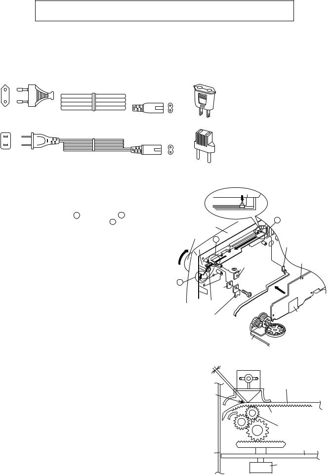
AC POWER SUPPLY CORD AND AC PLUG ADAPTOR
QACCE0007AW00 |
|
|
|
|
|
QPLGA0250AFZZ |
|
|
|
|
|
|
|
|
|
|
|
|
|
|
|
|
|
|
|
|
|
|
|
|
|
|
|
|
|
|
|
|
|
|
|
QACCA0001SJ00 |
|
|
|
|
QPLGA0253AFZZ |
|||||||
|
|
|
|
|
|
|
|
|
|
|
|
|
|
|
|
|
|
|
|
|
|
|
|
|
|
|
|
|
|
|
|
|
|
|
|
|
|
|
|
|
|
|
|
|
|
|
|
|
|
|
|
FITTING OF DIAL POINTER
1.Remove the Main PWB, the Graphic Equalizer PWB, the Volume PWB and the Fine Tuning PWB. (See Figure 4-2 in the "Disassembly" on page 4.)
2.Remove the dial pointer guide and PWB.
3.Insert the dial pointer from A , lead it under B , hang it on the tuner gear and then pass it through C .
4.Replace the Main PWB, the Graphic Equalizer PWB, the Volume PWB and the Fine Tuning PWB.
5.Rotate the tuning knob in the arrow direction until it stops. (Set the tuner variable capacitor to "0" point (F-LOW state).)
6.Adjust the dial pointer so that its stopper becomes the Figure 2-2 position. (Adjust the engagement of the pointer gear and the tuner gear to get the minimum space between the PWB and the stopper.) This position is the "0" point.
7.Screw up the PWB and the dial pointer guide.
"0" Point
Dial Pointer(211)
A
Front Cabinet
Tuning Knob
B
Dial Pointer(211)
Graphic Equalizer
Fine Tuning PWB
 PWB
PWB
C |
|
Screw(601) |
|
ø3x10mm |
|
|
PWB |
|
|
|
|
|
Tuner |
|
|
Gear |
|
Dial Pointer Guide |
Volume PWB |
|
|
(218) |
|
Main PWB
Figure 2-1
Make the minimum space.
 PWB
PWB
Dial Pointer
Stopper
Pointer Gear
Tuner Gear
Main PWB
Front Cabinet
Variable Capacitor
Figure 2-2
– 2 –
WF-1100W
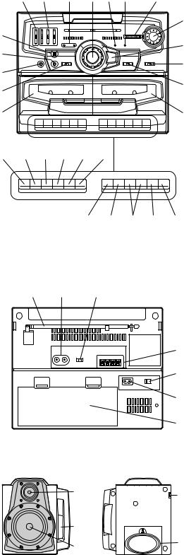
NAMES OF PARTS
1.Extra Bass Control
2.Graphic Equalizer Controls
3.Power/(TAPE 2) Play Direction Indicators
4.Volume Control
5.Surround Indicator
6.FM Stereo Indicator
7.Fine Tuning Control
8.Built-in Microphone
9.Mixing Microphone Socket
10.Headphone Socket
11.Function Selector Switch
12.(TAPE 1) Cassette Compartment
13.Tuning Control
14.Surround Switch
15.Band Selector Switch
16.Dubbing Speed/Built-in Microphone/FM Mode Switch
17.(TAPE 2) Cassette Compartment
18.(TAPE 1) Record Button
19.(TAPE 1) Play Button
20.(TAPE 1) Rewind Button
21.(TAPE 1) Fast Forward Button
22.(TAPE 1) Stop/Eject Button
23.(TAPE 1) Pause Button
24.(TAPE 2) Reverse Mode Switch
25.(TAPE 2) Play Button
26.(TAPE 2) Fast Wind Buttons
27.(TAPE 2) Stop/Eject Button
28.(TAPE 2) Direction Switch
1 |
2 |
3 |
4 |
5 6 |
7 |
8 |
|
|
|
|
13 |
|
|
|
|
14 |
|
9 |
|
|
|
|
|
|
|
|
|
15 |
|
10 |
|
|
|
|
|
|
|
|
|
16 |
|
11 |
|
|
|
|
|
|
|
|
|
|
|
12 |
|
|
|
|
17 |
18 19 20 21 22 23 |
|
||||
24 25 26 27 28
29 30 31
29.FM/SW Telescopic Rod Aerial
30.CD/Line Input Sockets
31.Beat Cancel Switch
32.Speaker Terminals
33.AC Voltage Selector
34.AC Power Input Socket
35.Battery Compartment
36.Tweeter
37.Bass Reflex Duct
38.Woofer
39.Speaker Release Lever
40.Speaker Wire
32
33
34
35
36 |
39 |
37 38  40
40
– 3 –

WF-1100W
DISASSEMBLY
Caution on Disassembly
Follow the below-mentioned notes when disassembling the unit and reassembling it, to keep it safe and ensure excellent performance:
1.Take cassette tape out of the unit.
2.Be sure to remove the power supply plug from the wall outlet before starting to disassemble the unit and remove the batteries from the unit.
3.Take off nylon bands or wire holders where they need to be removed when disassembling the unit. After servicing the unit, be sure to rearrange the leads where they were before disassembling.
4.Take sufficient care on static electricity of integrated circuits and other circuits when servicing.
MAIN UNIT
STEP |
REMOVAL |
|
|
|
PROCEDURE |
FIGURE |
|
|
|
|
|
|
|
|
|
1 |
Front Cabinet/ |
1. |
Battery Compartment Lid. |
4-1 |
|||
|
Rear Cabinet |
|
|
|
|
(A1)x1 |
|
|
|
................................. |
|
|
|
||
|
|
2. |
Screw ................... |
(A2)x3 |
|
||
|
|
3. |
Screw ................... |
(A3)x4 |
|
||
|
|
4. |
Socket .................. |
(A4)x1 |
|
||
|
|
|
|
|
|
|
|
2 |
Main PWB/ |
1. |
Knob ..................... |
(B1)x1 |
4-2 |
||
|
Graphic Equalizer |
2. |
Socket .................. |
(B2)x3 |
|
||
|
PWB/ |
3. |
Screw ................... |
(B3)x5 |
|
||
|
Volume PWB/ |
4. Screw ................... |
(B4)x2 |
|
|||
|
Fine Tuning PWB |
5. |
Mic ....................... |
(B5)x1 |
|
||
|
|
|
|
|
|
|
|
3 |
Tape mechanism |
1. |
Open the cassette holder. |
4-2 |
|||
|
|
2. |
Screw ................... |
(C1)x6 |
|
||
|
|
|
|
|
|
|
|
4 |
Power PWB/ |
1. Screw ................... |
(D1)x3 |
4-3 |
|||
|
Terminal A PWB/ |
2. |
Screw ................... |
(D2)x2 |
|
||
|
Terminal B PWB |
3. |
Bracket ................. |
(D3)x1 |
|
||
|
|
4. |
Screw ................... |
(D4)x2 |
|
||
|
|
5. |
Hook ..................... |
(D5)x2 |
|
||
|
|
|
|
|
|
|
|
SPEAKER UNIT
STEP |
REMOVAL |
|
PROCEDURE |
FIGURE |
|
|
|
|
|
|
|
1 |
Speaker |
1. Screw ................... |
(E1)x5 |
4-4 |
|
|
|
2. |
Front Panel .......... |
(E2)x1 |
|
|
|
3. |
Screw ................... |
(E3)x2 |
|
|
|
4. |
Screw ................... |
(E4)x4 |
|
|
|
|
|
|
|
Fine Tuning PWB Volume |
Graphic |
|
||
|
PWB |
|
|
|
|
|
Equalizer PWB |
||
|
|
|
||
Front Cabinet |
|
|
|
(B1)x1 |
|
|
|
Nat |
|
|
|
|
Washer |
|
Main PWB |
|
|
|
|
|
|
|
|
Open |
(B4)x2 |
|
(B5)x1 |
|
|
ø3x10mm |
|
|
||
|
|
|
|
|
(C1)x4 |
|
|
|
|
ø3x10mm |
|
|
|
|
(B3)x5 |
|
|
|
Cassette |
|
|
|
Holder |
|
ø3x10mm |
|
|
|
|
|
(C1)x2 |
Tape (Left/Right) |
||
(B2)x3 |
|
|||
|
ø3x10mm |
Mechanism |
||
Figure 4-2
Power
Rear Cabinet
Transeformer
Voltage Selector
AC Socket
Power
PWB
(D5)x2
(D1)x3  ø3x10mm
(D2)x2
ø4x16mm
(D3)x1 |
|
(D4)x2 |
Terminal B |
ø3x10mm |
PWB |
|
Terminal A |
PWB
|
Front Panel |
Figure 4-3 |
|
|
|
|
|
Main PWB |
(E2)x1 |
(E3)x2 |
|
|
Tweeter |
ø3x10mm |
|
|
Woofer |
Speaker Cord |
Speaker |
(A2)x1 |
|
Holder |
|
|
Cord |
||
ø3x6mm |
|
|
|
(A4)x1 |
|
|
|
|
|
Driver |
|
|
|
|
Front  Cabinet
 (A3)x4
ø3x20mm
(A2)x1 |
(E4)x4 |
|
|
ø3x10mm |
|
||
ø3x10mm |
|
||
|
|
||
|
Main Unit |
|
|
|
(A2)x1 |
|
|
Rear |
ø3x6mm |
|
|
Speaker |
|
||
Cabinet |
|
||
Release |
(E1)x5 |
||
(A1)x1 |
|||
Lever Speaker Box |
ø4x16mm |
||
|
|||
Figure 4-1 |
Figure 4-4 |
|
– 4 –
WF-1100W
NOTES ON SCHEMATIC DIAGRAM
•Resistor:
To differentiate the units of resistors, The symbol as K and M are used: the symbol K means 1000 ohm and the symbol M means 1000 kohm and the resistor without any symbol is an ohm resistor. The resistor designated “Fusible” is a fuse type resistor.
•Capacitor:
To indicate the unit of capacitor, a symbol P is used: this symbol P means pico-farad and the unit of the capacitor without such a symbol is microfarad. As to electrolytic capacitor, the expression “capacitance/withstand voltage” is used.
(CH),(RH),(UJ): Temperature compensation (ML): Mylar type
(S): Styrol type
•The indicated voltage in each section is the one measured by Digital Multimeter between such a section and the chassis with no signal given.
•Schematic diagram and Wiring Side of P.W. Board for this model are subject to change for improvement without prior notice.
•Parts marked with “ ” (
” ( 


 ) are important for maintaining the safety of the set. Be sure to replace these parts with specified ones for maintaining the safety and performance of the set.
REF. NO. |
DESCRIPTION |
POSITION |
|
|
|
SW1 |
BAND SELECTOR |
FM |
|
|
|
SW101 |
RECORD/PLAYBACK |
PLAYBACK |
|
|
|
SW102 |
BEAT CANCEL |
A |
|
|
|
SW103 |
DUBBING SPEED/MIC/ |
MIC/FM MONO |
|
FM MODE |
|
|
|
|
SW401 |
SURROUND |
ON |
|
|
|
SW501 |
FUNCTION SELECTOR |
CD/LINE |
|
|
|
SW501A |
TAPE 2 MAIN |
OFF |
|
|
|
SW502 |
TAPE 1 MAIN |
OFF |
|
|
|
SW503 |
TAPE 2 PLAY |
OFF |
|
|
|
SW504 |
TAPE 2 DIRECTION |
A |
|
|
|
SW601 |
VOLTAGE SELECTOR |
AC220-240V |
|
|
|
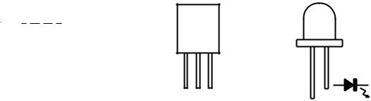
FRONT
VIEW
FRONT
VIEW
E B C |
|
KTA1271 Y |
333ID |
KTC3199 GR |
|
KTC3203 Y |
|
Figure 5 TYPES OF TRANSISTOR AND LED
VOLTAGE
IC2 (LA1805)
PIN |
1 |
2 |
3 |
4 |
5 |
6 |
7 |
8 |
9 |
10 |
11 |
12 |
|
FM |
1.6V |
1.6V |
5.8V |
0.2V |
1.6V |
0V |
10.7V |
0V |
2.4V |
2.4V |
5.1V |
0.9V |
|
MW/SW1/SW2 |
1.7V |
1.7V |
6.5V |
1.4V |
1.7V |
0V |
10.7V |
0V |
2.4V |
2.4V |
6.4V |
0.9V |
|
|
|
|
|
|
|
|
|
|
|
|
|
|
|
PIN |
13 |
14 |
15 |
16 |
17 |
18 |
19 |
20 |
21 |
22 |
23 |
24 |
|
FM |
1.1V |
2.1V |
1V |
1.8V |
1.6V |
1.6V |
0.4V |
5.8V |
5.8V |
0.5V |
1.6V |
1.4V |
|
MW/SW1/SW2 |
0V |
1.9V |
1.8V |
1.8V |
1.7V |
1.6V |
1.1V |
6.3V |
6.3V |
1.7V |
1.7V |
1.6V |
|
|
IC101 (TA8189N) |
|
|
|
|
|
|
|
|
|
|
||
|
PIN |
1 |
2 |
3 |
4 |
5 |
6 |
7 |
8 |
9 |
10 |
11 |
12 |
|
PLAY |
0V |
0V |
1.3V |
1.3V |
1.4V |
1.4V |
0V |
0V |
2.1V |
1.3V |
0V |
0V |
|
REC |
0V |
0V |
1.3V |
1.3V |
1.4V |
1.4V |
0V |
0V |
2.1V |
1.3V |
0V |
0V |
|
|
|
|
|
|
|
|
|
|
|
|
|
|
|
PIN |
13 |
14 |
15 |
16 |
17 |
18 |
19 |
20 |
21 |
22 |
23 |
24 |
|
PLAY |
0.9V |
0V |
1.3V |
2.1V |
1.4V |
5.2V |
2.1V |
1.4V |
1.3V |
1.3V |
0V |
0V |
|
REC |
0.9V |
0V |
1.3V |
2.1V |
1.5V |
5.2V |
0V |
1.4V |
1.3V |
1.3V |
0V |
0V |
– 5 –
WF-1100W
ADJUSTMENT
MECHANISM SECTION
• Driving Force Check
Torque Meter |
Specified Value |
|
|
Play: TW-2412 |
Tape 1: Over 60 g |
|
Tape 2: Over 50 g |
|
|
• Torque Check
Torque Meter |
Specified Value |
|
|
|
|
|
Tape 1 |
Tape 2 |
|
|
|
Play: TW-2111 |
30 to 70 g.cm |
27 to 60 g.cm |
|
|
|
Fast Forward: TW-2231 |
Over 55 g.cm |
55 to 120 g.cm |
|
|
|
Rewind: TW-2231 |
Over 55 g.cm |
55 to 120 g.cm |
|
|
|
• Head Azimuth
Test Tape |
Instrument Connection |
|
|
MTT-114 |
Headphones Socket |
|
(Load resistance: 32 ohms) |
|
|
• Tape Speed (Normal only)
Test Tape |
Adjustment |
Specified |
Instrument |
|
Point |
Value |
Connection |
|
|
|
|
MTT-111 |
Tape 1,2:VR102 |
3,000 ± 60 Hz |
Headphones |
|
|
|
Socket |
|
|
|
(Loadresistance: |
|
|
|
32 ohms) |
|
|
|
|
DECK SECTION
•Bias Oscillation
•Beat Cancel Switch: A
Adjustment Point |
Specified value |
|
Instrument |
|||
|
|
|
|
|
|
Connection |
|
|
|
|
|
||
L301 |
|
100 kHz + 4 kHz |
|
Pin 1 of CNS102 |
||
|
|
|
|
|
|
|
|
|
|
|
|
|
|
|
|
|
|
Specified Value |
||
|
|
|
|
|
|
|
Beat Cancel |
|
|
A: 100 ± 4 kHz |
|
||
|
|
|
B: 94 ± 4 kHz |
|||
|
|
|
C: 104 ± 4 kHz |
|||
• Playback Amplifier Sensitivity Check |
|
|||||
|
|
|
|
|
|
|
Test tape |
Specified value |
Instrument Connection |
||||
|
|
|
|
|
|
|
MTT-118 |
2.5 V ± 3 dB |
Speaker terminal |
||||
|
|
|
|
(Load resistance: 8 ohms) |
||
|
|
|
|
|
|
|
TUNER SECTION
fL: Low-range frequency fH: High-renge frequency
• FM IF/RF
Test Stage |
Specified Value/ |
Instrument |
|
Adjusting |
|||
Connection |
|||
|
Point |
||
|
|
||
|
|
|
|
FM IF |
L9 |
Input: FM Antenna |
|
FM Detection |
L10 |
Output:Pin 9 of IC2 |
|
|
|
|
|
FM Band |
fL: L1 |
Input: Antenna |
|
Coverage |
fH: TC1 |
Output: Headphone Socket |
|
FM Tracking |
fL(88.0 MHz): L2 |
(Load resistance: |
|
|
fH(108 MHz): TC2 |
32 ohms) |
|
|
|
|
• AM IF/RF
Test Stage |
Specified Value/ |
Instrument |
|
Adjusting |
|||
Connection |
|||
|
|||
|
Point |
||
|
|
||
|
|
|
|
AM IF |
L11 |
Input: Antenna |
|
|
|
Output: Pin 9 of IC2 |
|
|
|
|
|
MW Band |
fL: L6 |
Input: Antenna |
|
Coverage |
fH: TC3 |
Output: Headphone Socket |
|
|
|
(Load resistance |
|
MW Tracking |
fL(600 kHz): L3 |
||
|
fH(1,400 kHz):TC4 |
32 ohms) |
|
SW1 Band |
fL(2.3 MHz): L7 |
|
|
Coverage |
fH(7.3 MHz): TC5 |
|
|
|
|
|
|
SW1 |
fL(2.6 MHz): L4 |
|
|
Tracking |
fH(6 MHz): TC6 |
|
|
|
|
|
|
SW2 Band |
fL(7.3 MHz): L8 |
|
|
Coverage |
fH(22 MHz): TC7 |
|
|
|
|
|
|
SW2 |
fL(8.5 MHz): L5 |
|
|
Tracking |
fH(19 MHz): TC8 |
|
|
|
|
|
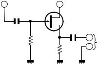
• VCO Frequency
Adjustment |
Specified value |
Instrument Connection |
Point |
|
|
|
|
|
VR1 |
76 kHz ± 200 Hz |
Pin 13, Pin 21 and ground |
|
|
of IC2 |
|
|
|
Note:
After preparing the test circuit shown in Fig. 6, connect the Pin 13, Pin 21 and ground of the IC2 with the test circuit, and measure the value.
Pin 13 of IC2 |
Pin 21 of IC2 |
|
||
|
|
D |
|
|
G |
|
FET: 2SK212 |
||
10 pF |
|
(or Other 2SK Type FET.) |
||
|
S |
|
||
|
|
|
||
1M ohm |
|
0.1 F |
TO FREQUENCY |
|
10K ohm |
COUNTER |
|||
|
||||
|
|
|||
Figure 6 VCO FREQUENCY TEST CIRCUIT
– 6 –
 Loading...