


PORTABLE STEREO COMPONENT SYSTEM
SYSTÈME STÉRÉO PORTABLE
SISTEMA COMPONENTE DEL EQUIPO PORTÁTIL
MODEL
MODÈLE
MODELO
WF-5000W
OPERATION MANUAL
MODE D’EMPLOI
MANUAL DE MANEJO
Thank you for purchasing this SHARP product. To obtain the best performance from this product, please read this manual carefully. It will guide you in operating your SHARP product.
Nous vous remercions d'avoir porté votre choix sur ce produit SHARP. Pour en tirer le meilleur parti, veuillez lire ce mode d'emploi très attentivement.
Muchas gracias por haber adquirido este producto SHARP. Lea atentamente este manual para conseguir el mejor rendimiento del aparato. Le servirá también como guía operativa de este producto SHARP.
SHARPSHARP
SHARP CORPORATION
06/2/22 WF-5000W(U)_FRONT.fm TINSEA095AWZZ

WF-5000W
ENGLISH
General Information
ENGLISH
Special notes
WARNINGS:
When the ON/STAND-BY button is set at STAND-BY position, mains voltage is still present inside the unit. When the ON/STAND-BY button is set at STAND-BY position, the unit may be brought into operation by the timer mode or remote control.
This unit contains no user serviceable parts. Never remove covers unless qualified to do so. This unit contains dangerous voltages, always remove mains plug from the socket before any service operation and when not in use for a long period.
To prevent fire or shock hazard, do not expose this appliance to dripping or splashing. No objects filled with liquids, such as vases, shall be placed on the apparatus.
Accessories
Please confirm that the following accessories are included.
|
|
|
|
|
|
|
|
|
|
|
|
|
|
|
|
|
|
|
|
|
|
|
|
|
|
|
|
|
|
|
|
|
|
Remote control |
|
1 |
|
"AA" size battery (UM/SUM-3, R6, |
|||||
|
||||||||||
|
|
|
|
|
HP-7 or similar) |
|
2 |
|||
|
|
|
|
|
|
|||||
|
|
|
|
|
|
|||||
|
|
|
|
|
|
|
|
|
|
|
|
|
|
|
|
|
|
|
|
|
|
|
|
|
|
|
|
|
|
|
|
|
|
|
|
|
|
|
|
|
|
|
|
AM loop aerial |
|
1 |
AC Lead |
|
1 |
|
|
Note:
Only the above accessories are included.
Contents
Page
General Information
Precautions . . . . . . . . . . . . . . . . . . . . . . . . . . . . . . . . . . . . . . . . . . . . . . . . . 2 Controls and indicators . . . . . . . . . . . . . . . . . . . . . . . . . . . . . . . . . . . . . 3 - 4
Preparation for Use
System connections . . . . . . . . . . . . . . . . . . . . . . . . . . . . . . . . . . . . . . . . 5 - 8 Remote control . . . . . . . . . . . . . . . . . . . . . . . . . . . . . . . . . . . . . . . . . . . . . . . 9
Basic Operation
General control . . . . . . . . . . . . . . . . . . . . . . . . . . . . . . . . . . . . . . . . . . . . . 10 Setting the clock (Remote control only) . . . . . . . . . . . . . . . . . . . . . . . . . 11
Radio
Listening to the radio . . . . . . . . . . . . . . . . . . . . . . . . . . . . . . . . . . . . . 12 - 13 Setting the FM/MW interval . . . . . . . . . . . . . . . . . . . . . . . . . . . . . . . . . . . . 13
Tape Playback
Listening to a cassette tape (TAPE 1 or TAPE 2) . . . . . . . . . . . . . . 14 - 15
Tape Recording
Recording to a cassette tape . . . . . . . . . . . . . . . . . . . . . . . . . . . . . . 15 - 17
Advanced Features
Timer and sleep operation (Remote control only) . . . . . . . . . . . . . 17 - 19 Enhancing your system . . . . . . . . . . . . . . . . . . . . . . . . . . . . . . . . . . . . . . 20
References
Troubleshooting chart . . . . . . . . . . . . . . . . . . . . . . . . . . . . . . . . . . . . . . . . 21 Specifications . . . . . . . . . . . . . . . . . . . . . . . . . . . . . . . . . . . . . . . . . . . . . . . 22
E-1
06/2/23 WF-5000W(U)NEW1.fm TINSEA095AWZZ
Precautions
General
Please ensure that the equipment is positioned in a well-ventilated area and ensure that there is at least 10 cm (4") of free space along the sides, top and back of the equipment.
10 cm (4")
10 cm(4")
Use the unit on a firm, level surface free from vibration.
Keep the unit away from direct sunlight, strong magnetic fields, excessive dust, humidity and electronic/electrical equipment (home computers, facsimiles, etc.) which generate electrical noise.
Do not place anything on top of the unit.
Do not expose the unit to moisture, to temperatures higher than 60˚C (140˚F) or to extremely low temperatures.
If your system does not work properly, disconnect the AC power lead from the wall socket. Plug the AC power lead back in, and then turn on your system.
In case of an electrical storm, unplug the unit for safety.
Hold the AC power plug by the head when removing it from the wall socket, as pulling the lead can damage internal wires.
The AC power plug/ AC power input socket is used as disconnect device and shall always remain readily operable.
Do not remove the outer cover, as this may result in electric shock. Refer internal service to your local SHARP service facility.
The ventilation should not be impeded by covering the ventilation openings with items, such as newspapers, tablecloths, curtains, etc.
No naked flame sources, such as lighted candles, should be placed on the apparatus.
Attention should be drawn to the environmental aspects of battery disposal. The apparatus is designed for used in moderate climate.
This unit should only be used within the range of 5˚C - 35˚C (41˚F - 95˚F).
Warning:
The voltage used must be the same as that specified on this unit. Using this product with a higher voltage other than that which is specified is dangerous and may result in a fire or other type of accident causing damage. SHARP will not be held responsible for any damage resulting from use of this unit with a voltage other than that which is specified.
Volume control
The sound level at a given volume setting depends on speaker efficiency, location and various other factors. It is advisable to avoid exposure to high volume levels, which occurs whilst turning the unit on with the volume control setting up high, or whilst continually listening at high volumes.
Condensation
Sudden temperature changes, storage or operation in an extremely humid environment may cause condensation inside the cabinet (tape heads, etc.) or on the transmitter on the remote control.
Condensation can cause the unit to malfunction. If this happens, leave the power on with no cassette in the unit until normal playback is possible (about 1 hour). Wipe off any condensation on the transmitter with a soft cloth before operating the unit.
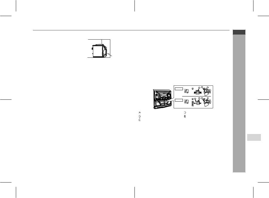
Cleaning the tape-handling parts
Dirty heads, capstans or pinch rollers can cause poor sound and tape jams. Clean these parts with a cotton swab moistened with commercial head/ pinch roller cleaner or isopropyl alcohol.
When cleaning the heads, pinch rollers, etc., unplug the unit which contains high voltages.
|
A |
B |
C |
TAPE 1 |
|
||
|
|
|
|
D |
E B |
C |
|
TAPE 2 |
|
|
|
|
|
|
|
|
|
|
|
|
|
|
|
|
|
|
|
|
|
|
|
|
|
|
|
|
|
|
|
|
|
|
|
|
|
|
|
|
Playback head |
|
|
Erase head |
|||||||
|
|
|
|||||||||
|
Capstans |
|
|
Recording/Playback head |
|||||||
|
|
|
|||||||||
|
Pinch rollers |
|
|
|
|
|
|
|
|
|
|
|
|
|
|
|
|
|
|
|
|
|
|
After long use, the deck's heads and capstans may become magnetised, causing poor sound. Demagnetise these parts once every 30 hours of playing/recording time by using a commercial tape head demagnetiser. Read the demagnetiser's instructions carefully before use.
Cleaning the cabinet
Periodically wipe the cabinet with a soft cloth and a diluted soap solution, then with a dry cloth.
Caution:
Do not use chemicals for cleaning (petrol, paint thinner, etc.). It may damage the cabinet finish.
Do not apply oil to the inside of the unit. It may cause malfunctions.
WF-5000W
ENGLISH
General Information
E-2
06/2/28 WF-5000W(U)NEW1.fm TINSEA095AWZZ

WF-5000W
ENGLISH
General Information
E-3
Controls and indicators
1 |
2 |
3 |
4 |
5 |
6 |
7 |
8 9 10 |
11 |
12 |
13 14 15 16 17 18 |
|
|
19 20 21 |
22 |
23 |
|||||||||||||||||||||||
1 |
|
2 |
|
|
|
3 |
4 |
5 |
6 |
|
|
|
|
|
||||||||||||||
|
|
|
|
|
|
|
|
|
|
|
|
|
|
|
|
|
|
|
|
|
|
|
|
|
|
|
|
|
|
|
|
|
|
|
|
|
|
|
|
|
|
|
|
|
|
|
|
|
|
|
|
|
|
|
|
|
|
|
|
|
|
|
|
|
|
|
|
|
|
|
|
|
|
|
|
|
|
|
|
|
|
|
|
|
|
|
|
|
|
|
|
|
|
|
|
|
|
|
|
|
|
|
|
|
|
|
|
|
|
|
|
|
|
|
|
|
|
|
|
|
|
|
|
|
|
|
|
|
|
|
|
|
|
|
|
|
|
|
|
|
|
|
|
|
|
|
|
|
|
|
|
|
|
|
|
|
|
|
|
|
|
|
|
|
|
|
|
|
|
|
|
|
|
|
|
|
|
|
|
|
|
|
|
|
|
|
|
|
|
|
|
|
|
|
|
|
|
|
|
|
|
|
|
|
|
|
|
|
|
|
|
|
|
|
|
|
|
|
|
|
|
|
|
|
|
|
|
|
|
|
|
|
|
|
|
|
|
|
|
|
|
|
|
|
|
|
|
|
|
|
|
|
|
|
|
|
|
|
|
|
|
|
|
|
|
|
|
|
|
|
|
|
|
|
|
|
|
|
|
|
|
|
|
|
|
|
|
|
|
|
|
|
|
|
|
|
|
|
|
|
|
|
|
|
|
|
|
|
|
|
|
|
|
|
|
|
|
|
|
|
|
|
|
|
|
|
|
|
|
|
|
|
|
|
|
|
|
|
|
|
|
|
|
|
|
|
|
|
|
|
|
|
|
|
|
|
|
|
|
|
|
|
|
|
|
|
|
|
|
|
|
|
|
|
|
|
|
|
|
|
|
|
|
|
|
|
|
|
|
|
|
|
|
|
|
|
|
|
|
|
|
|
|
|
|
|
|
|
|
|
|
|
|
|
|
|
|
|
|
|
|
|
|
|
|
|
|
|
|
|
|
|
|
|
|
|
|
|
|
|
|
|
|
|
|
|
|
|
|
|
|
|
|
|
|
|
|
|
|
|
|
|
|
7 8
Front panel |
|
|
Reference page |
1. Headphone Socket . . . . . . . . . . . . . . . . . . . . . . . . . . . |
. . . . . . . . . . . . 20 |
2. On/Stand by Button . . . . . . . . . . . . . . . . . . . . . . . . . . . . |
. . . . . . . . . . . 10 |
3. Built In Microphone . . . . . . . . . . . . . . . . . . . . . . . . . . . . |
. . . . . . . . . . . 16 |
4. Tape (1 2) Button . . . . . . . . . . . . . . . . . . . . . . . . . . . |
. . . . . . . . . . . 14 |
5. Timer Indicator . . . . . . . . . . . . . . . . . . . . . . . . . . . . . . . |
. . . . . . . . . . . 18 |
6. Tuner (Band) Button. . . . . . . . . . . . . . . . . . . . . . . . . . . . |
. . . . . . . . . . . 12 |
7. CD/Line Button . . . . . . . . . . . . . . . . . . . . . . . . . . . . . . . |
. . . . . . . . . . . 20 |
8. Tuning Up Button . . . . . . . . . . . . . . . . . . . . . . . . . . . . . |
. . . . . . . . . . . 12 |
9. Tuning Down Button . . . . . . . . . . . . . . . . . . . . . . . . . . . |
. . . . . . . . . . . 12 |
10. Simba Mode/Demo Button . . . . . . . . . . . . . . . . . . . . . . |
. . . . . . . . 10, 21 |
11. Volume Control. . . . . . . . . . . . . . . . . . . . . . . . . . . . . . . . |
. . . . . . . . . . . 10 |
12. Microphone Socket . . . . . . . . . . . . . . . . . . . . . . . . . . . . |
. . . . . . . . 15, 16 |
13. Tape 1 Play Button . . . . . . . . . . . . . . . . . . . . . . . . . . . . |
. . . . . . . . . . . 14 |
14. Tape 1 Stop Button . . . . . . . . . . . . . . . . . . . . . . . . . . . . |
. . . . . . . . . . . 14 |
15. Tape 1 Rewind Button . . . . . . . . . . . . . . . . . . . . . . . . . . |
. . . . . . . . . . . 14 |
16. Tape 1 Fast Forward Button . . . . . . . . . . . . . . . . . . . . . |
. . . . . . . . . . . 14 |
17. Tape Continuous Playback Button . . . . . . . . . . . . . . . |
. . . . . . . . . . . 14 |
18. Tape High Speed Dubbing Button . . . . . . . . . . . . . . . . |
. . . . . . . . 14, 17 |
19. Tape 2 Reverse Play Button . . . . . . . . . . . . . . . . . . . . . |
. . . . . . . . 14, 16 |
20. Tape 2 Forward Play Button . . . . . . . . . . . . . . . . . . . . . |
. . . . . . . . 14, 16 |
21. Tape 2 Stop Button . . . . . . . . . . . . . . . . . . . . . . . . . . . . |
. . . . . . . . . . . 14 |
22. Tape 2 Fast Wind Buttons . . . . . . . . . . . . . . . . . . . . . . |
. . . . . . . . . . . 16 |
23. Tape 2 Record Pause Button . . . . . . . . . . . . . . . . . . . . |
. . . . . . . . . . . 16 |
Rear panel |
|
|
Reference page |
1. AM Loop Aerial Socket . . . . . . . . . . . . . . . . . . . . . . . . . . . . . . . . . . . . . 6
2. Beat Cancel . . . . . . . . . . . . . . . . . . . . . . . . . . . . . . . . . . . . . . . . . . . . . 16
3. CD/LINE Input Sockets . . . . . . . . . . . . . . . . . . . . . . . . . . . . . . . . . 18, 20
4. Speaker Terminals . . . . . . . . . . . . . . . . . . . . . . . . . . . . . . . . . . . . . . . . . 6
5. AC Power Lead . . . . . . . . . . . . . . . . . . . . . . . . . . . . . . . . . . . . . . . . . . . . 7
6. Voltage Selector . . . . . . . . . . . . . . . . . . . . . . . . . . . . . . . . . . . . . . . . . . . 7
7. Battery Compartment. . . . . . . . . . . . . . . . . . . . . . . . . . . . . . . . . . . . . . . 8
8. DC Power Terminal . . . . . . . . . . . . . . . . . . . . . . . . . . . . . . . . . . . . . . . . 8
Speaker system
1. Tweeter
2. Bass Reflex Hole
3. Woofer 1
4. Speaker Wire
2
3
4
06/2/23 WF-5000W(U)NEW1.fm TINSEA095AWZZ
1 2 3 |
4 |
5 |
6 7 8
9 14 


 10
10
13
12 11
1 |
11 |
2 |
3 |
12 |
|
4 |
||
13 |
||
5 |
||
14 |
||
6 |
||
15 |
||
7 |
16 |
|
8 |
17 |
|
9 |
18 |
|
10 |
Display |
|
|
Reference page |
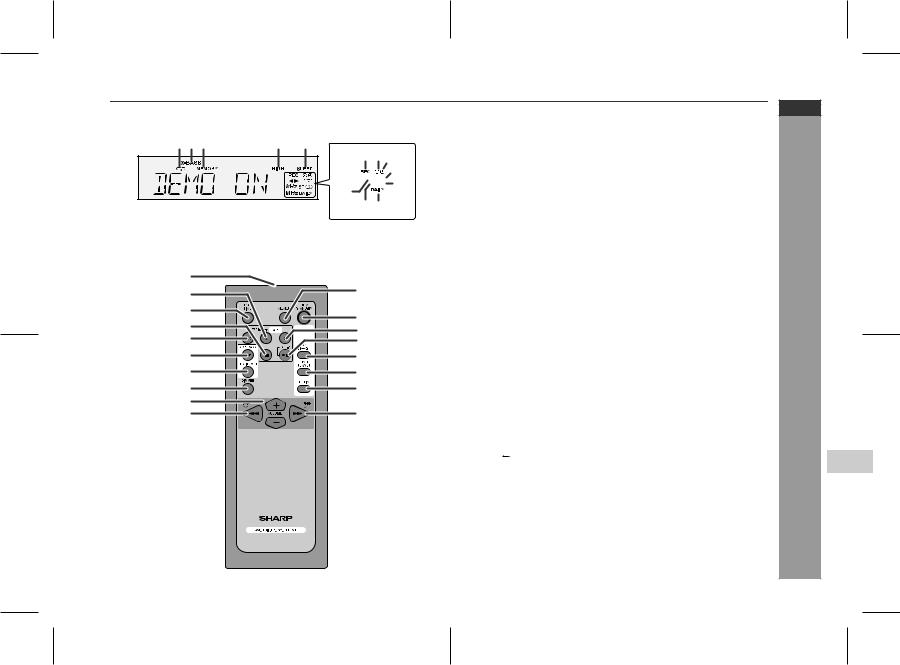
1. Tape Continuous Playback Indicator . . . . . . . . . . . . |
. . . . . . . . . . . . 14 |
2. Extra Bass Indicator . . . . . . . . . . . . . . . . . . . . . . . . . |
. . . . . . . . . . . . 10 |
3. Memory Indicator . . . . . . . . . . . . . . . . . . . . . . . . . . . . . |
. . . . . . . . . . . 13 |
4. High Speed Dubbing Indicator . . . . . . . . . . . . . . . . . . |
. . . . . . . . . . . 17 |
5. Sleep Indicator . . . . . . . . . . . . . . . . . . . . . . . . . . . . . . . |
. . . . . . . . . . . 19 |
6. Tape 2 Record Indicator . . . . . . . . . . . . . . . . . . . . . . . |
. . . . . . . . . . . 17 |
7. Timer Play Indicator . . . . . . . . . . . . . . . . . . . . . . . . . . . |
. . . . . . . . . . . 18 |
8. Timer Recording Indicator . . . . . . . . . . . . . . . . . . . . . |
. . . . . . . . . . . 18 |
9. Tape 2 Reverse Mode Indicator . . . . . . . . . . . . . . . . . |
. . . . . . . . 14, 16 |
10. FM Stereo Receiving Indicator . . . . . . . . . . . . . . . . . . |
. . . . . . . . . . . 12 |
11. Daily Timer Indicator . . . . . . . . . . . . . . . . . . . . . . . . . . |
. . . . . . . . . . . 18 |
12. FM Stereo Mode Indicator . . . . . . . . . . . . . . . . . . . . . . |
. . . . . . . . . . . 12 |
13. Tape Play Indicator . . . . . . . . . . . . . . . . . . . . . . . . . . . |
. . . . . . . . . . . 14 |
14. Tape 2 Reverse Play Indicator . . . . . . . . . . . . . . . . . . . |
. . . . . . . . . . . 14 |
Remote control |
|
|
Reference page |
1. Remote Control Transmitter . . . . . . . . . . . . . . . . . . . . |
. . . . . . . . . . . . 9 |
2. Tape 2 Reverse Play Button . . . . . . . . . . . . . . . . . . . . |
. . . . . . . . . . . 14 |
3. Clock/Timer Button . . . . . . . . . . . . . . . . . . . . . . . . . . . |
. . . . . . . . 11, 17 |
4. Tape Stop Button . . . . . . . . . . . . . . . . . . . . . . . . . . . . . |
. . . . . . . . . . . 14 |
5. Tape 2 Reverse Mode Button . . . . . . . . . . . . . . . . . . . |
. . . . . . . . . . . 14 |
6. Simba Mode/Demo Button . . . . . . . . . . . . . . . . . . . . . |
. . . . . . . . . . . 10 |
7. Equaliser Mode Select Button . . . . . . . . . . . . . . . . . . |
. . . . . . . . . . . 10 |
8. Dimmer Button . . . . . . . . . . . . . . . . . . . . . . . . . . . . . . . |
. . . . . . . . . . . 10 |
9. Volume Up and Down Buttons . . . . . . . . . . . . . . . . . . |
. . . . . . . . . . . 10 |
10. Tape Rewind, Tuner Preset Down, |
|
Time Down Button . . . . . . . . . . . . . . . . . . . . . . . . . . . |
11, 12, 14, 15, 17 |
11. Memory Button . . . . . . . . . . . . . . . . . . . . . . . . . . . . . . . |
. . . . . . . . 11, 17 |
12. On/Stand-by Button . . . . . . . . . . . . . . . . . . . . . . . . . . . |
. . . . . . . . . . . 10 |
13. Tape Play Button . . . . . . . . . . . . . . . . . . . . . . . . . . . . . |
. . . . . . . . . . . 14 |
14. Tape Record Pause Button . . . . . . . . . . . . . . . . . . . . . |
. . . . . . . . . . . 16 |
15. Tape (1 2) Button . . . . . . . . . . . . . . . . . . . . . . . . . . |
. . . . . . . . . . . 14 |
16. Tuner (Band) Button . . . . . . . . . . . . . . . . . . . . . . . . . . |
. . . . . . . . . . . 12 |
17. CD/Line Button . . . . . . . . . . . . . . . . . . . . . . . . . . . . . . . |
. . . . . . . . 18, 20 |
18. Tape Fast Forward, Tuner Preset Up, |
|
Time Up Button . . . . . . . . . . . . . . . . . . . . . . . . . . . . . |
11, 12, 14, 15, 17 |
WF-5000W
ENGLISH
General Information
E-4
06/3/31 |
WF-5000W(U)1.fm |
TINSEA095AWZZ |

WF-5000W System connections
ENGLISH
AM Loop aerial
FM Rod aerial
Preparation for Use
DC power connection (see page 8) |
AC power connection (see page 7) |
E-5
06/2/23 WF-5000W(U)NEW1.fm TINSEA095AWZZ

Detachable speakers
Set the FUNCTION switch to STAND-BY before connecting or disconnecting the speakers.
Mounting the speakers to the main unit
Fit the grooves of the speaker to the guides on the main unit, and then slide the speaker all the way down to lock it in place.
Removing the speakers from the main unit
Push the RELEASE lever as shown in the illustration to unlock the speaker, and then lift up the speaker to remove it from the main unit.
Speaker connection
Connect each speaker wire to the SPEAKER terminals as shown. Use speakers with an impedance of 8 ohms or more, as lower impedance speakers can damage the unit.
Right speaker |
|
|
|
|
|
|
|
|
|
|
|
|
|
|
|
|
Left speaker |
|||||||||||
|
|
|
|
|
|
|
|
|
|
|
|
|
|
|
|
|
|
|
|
|
|
|
|
|
|
|
|
|
|
|
|
|
|
|
|
|
|
|
|
|
|
|
|
|
|
|
|
|
|
|
|
|
|
|
|
|
|
|
|
|
|
|
|
|
|
|
|
|
|
|
|
|
|
|
|
|
|
|
|
|
|
|
|
|
|
|
|
|
|
|
|
|
|
|
|
|
|
|
|
|
|
|
|
|
|
|
|
|
|
|
|
|
|
|
|
|
|
|
|
|
|
|
|
|
|
|
|
|
|
|
|
|
|
|
|
|
|
|
|
|
|
|
|
|
|
|
|
|
|
|
|
|
|
|
|
|
|
|
|
|
|
|
|
|
|
|
|
|
|
|
|
|
|
1 |
2 |
3 |
|
|
|
Red |
Red |
|
|
|
Black |
Caution:
Connect the black wire to the minus (-) terminal, and the red wire to the plus
(+) terminal.
Do not mix the right channel and left channel wiring when connecting the speakers to the unit.
Do not let the bare speaker wires touch each other as this may damage the amplifier and/or speakers.
Do not stand or sit on the speakers. If the speakers fall or collapse, you may be injured.
Aerial Adjustment
Supplied AM Loop aerial:
Connect the AM loop aerial to the AM LOOP socket. Position the AM loop aerial for optimum reception.
Note:
Placing the aerial on the unit or near the AC power lead may cause noise pickup. Place the aerial away from the unit for better reception.
WF-5000W
ENGLISH
Preparation for Use
E-6
06/2/23 WF-5000W(U)NEW1.fm TINSEA095AWZZ

WF-5000W
ENGLISH
Preparation for Use
System connections (continued)
To the wall socket
AC 110V |
|
|
|
|
|
|
AC 220V |
- 127V |
|
|
|
|
|
|
- 240V |
|
|
|
|
|
|
||
|
VOLTAGE |
||||||
|
SELECTOR |
||||||
AC 110V |
|
|
|
|
|
|
AC 220V |
|
|
|
|
|
|
||
- 127V |
|
|
|
|
|
|
- 240V |
|
|
|
|
|
|
||
VOLTAGE
SELECTOR
110-127/220-240 V
50/60 Hz
Setting the AC voltage selector
Check the setting of the AC voltage selector located on the rear panel before plugging the unit into a wall socket. If necessary, adjust the selector to correspond to the AC power voltage used in your area.
Selector adjustment:
Slide the selector with a screwdriver to the appropriate voltage number (AC 110 - 127 V or AC 220 - 240 V).
AC power connection
After checking all the connections have been made correctly, plug the AC power lead of this unit into the wall socket. If you plug the unit first, the unit will enter the demonstration mode.
Notes:
The unit will start the tape initialisation when plugged in to the wall socket. During this process, initialising sound will be heard and the unit cannot be turned on. Wait until the process is finished.
Unplug the AC power lead from the wall socket if the unit will not be in use for a prolonged period of time.
Demonstration mode
The first time the unit is plugged in, the unit will enter the demonstration mode. You will see words scroll.
To cancel the demonstration mode:
When the unit is in the power stand-by mode (demonstration mode), press the SIMBA MODE/DEMO button. The demonstration mode will be cancelled and the display will disappear.
To return to the demonstration mode:
When the unit is in the power stand-by mode, press the SIMBA MODE/DEMO button again.
Notes:
When the power is on, the SIMBA MODE/DEMO button can be used to select the simba mode.
Demonstration mode will not be displayed when DC Adaptor is connected or when battery is in use.
E-7
06/3/21 |
WF-5000W(U)2.fm |
TINSEA095AWZZ |
 Loading...