


UX-510UA
FO-1470U
SERVICE MANUAL
No. 00ZUX510UASME
FACSIMILE
UX-510A
MODEL FO-1470
Illustration: UX-510UA |
SELECTION CODE |
DESTINATION |
|
U |
U.S.A. |
||
open |
|||
|
|
||
LCR |
|
|
www.OpenLCR.com
CONTENTS
CHAPTER 1. GENERAL DESCRIPTION |
|
[1] Specifications ............................................ |
1-1 |
[2] Operation panel ......................................... |
1-2 |
[3] Transmittable documents .......................... |
1-3 |
[4] Installation ................................................. |
1-4 |
[5] Quick reference guide ............................... |
1-9 |
CHAPTER 2. ADJUSTMENTS |
|
[1] Adjustments .............................................. |
2-1 |
[2] Diagnostics and service soft switch .......... |
2-2 |
[3] Troubleshooting ...................................... |
2-19 |
[4] Error code table ....................................... |
2-20 |
CHAPTER 3. MECHANISM BLOCKS |
|
[1] General description ................................... |
3-1 |
[2] Disassembly and assembly |
|
procedures ....................................... |
3-4 |
CHAPTER 4. DIAGRAMS |
|
[1] Block diagram ............................................ |
4-1 |
[2] Wiring diagram .......................................... |
4-2 |
[3] Point-to-point diagram ............................... |
4-3 |
CHAPTER 5. CIRCUIT DESCRIPTION |
|
[1] Circuit description ..................................... |
5-1 |
[2] Circuit description of control PWB ............ |
5-2 |
[3] Circuit description of TEL/LIU PWB .......... |
5-8 |
[4] Circuit description of |
|
power supply PWB ............................ |
5-11 |
[5] Circuit description of CCD PWB .............. |
5-11 |
CHAPTER 6. CIRCUIT SCHEMATICS AND |
|
PARTS LAYOUT |
|
[1] Control PWB circuit ................................... |
6-1 |
[2] TEL/LIU PWB circuit.................................. |
6-9 |
[3] Power supply PWB circuit ...................... |
6-13 |
[4] CCD PWB circuit ..................................... |
6-15 |
[5] Operation panel PWB circuit ................... |
6-16 |
CHAPTER 7. OPERATION FLOWCHART |
|
[1] Protocol ..................................................... |
7-1 |
[2] Power on sequence ................................... |
7-2 |
CHAPTER 8. OTHERS |
|
[1] Service tools ............................................. |
8-1 |
[2] IC signal name .......................................... |
8-4 |
[3] Changing the record paper size ................ |
8-6 |
PARTS GUIDE |
|
Parts marked with " " are important for maintaining the safety of the set. Be sure to replace these parts with specified ones for maintaining the safety and performance of the set.
This document has been published to be used
SHARP CORPORATION for after sales service only.
The contents are subject to change without notice.

UX-510UA
FO-1470U
CAUTION FOR BATTERY REPLACEMENT
(Danish) ADVARSEL ! Lithiumbatteri-Eksplosionsfare ved fejlagtig håndtering.
Udskiftning må kun ske med batteri af samme fabrikat og type. Levér det brugte batteri tilbage til leverandoren.
(English) Caution !
Danger of explosion if battery is incorrectly replaced.
Replace only with the same or equivalent type recommended by the equipment manufacturer.
Discard used batteries according to manufacturer’s instructions.
(Finnish) VAROITUS
Paristo voi räjähtää, jos se on virheellisesti asennettu.
Vaihda paristo ainoastaan laitevalmistajan suosittelemaan tyyppiin. Hävitä käytetty paristo valmistajan ohjeiden mukaisesti.
(French) |
ATTENTION |
Il y a danger d’explosion s’ il y a remplacement incorrect |
|
de la batterie. Remplacer uniquement avec une batterie du même type ou d’un type recommandé par le constructeur. Mettre au rébut les batteries usagées conformément aux instructions du fabricant.
(Swedish) VARNING
Explosionsfare vid felaktigt batteribyte. Använd samma batterityp eller en ekvivalent typ som rekommenderas av apparattillverkaren. Kassera använt batteri enligt fabrikantens instruktion.
(German) Achtung
Explosionsgefahr bei Verwendung inkorrekter Batterien.
Als Ersatzbatterien dürfen nur Batterien vom gleichen Typ oder vom Hersteller empfohlene Batterien verwendet werden.
Entsorgung der gebrauchten Batterien nur nach den vom Hersteller angegebenen Anweisungen.

CHAPTER 1. GENERAL DESCRIPTION
[1] Specifications
Automatic dialing: |
Rapid Key Dialing: 36 numbers |
|
Speed Dialing: 63 numbers |
Imaging film: |
Initial starter roll (included with |
|
machine): Approx. 60 letter-size pages |
|
Replacement roll: |
|
UX-15CR/FO-15CR (One roll yields |
|
approx. 500 letter-size pages) |
Memory size* : |
512 KB (approx. 30 average pages with |
|
ECM turned off) |
Modem speed: |
14,400 bps with Automatic Fallback to |
|
2400 bps. |
Transmission time* : |
Approx. 6 seconds |
Resolution: |
Horizontal: |
|
203 pels/inch (8 dots/mm) |
|
Vertical: |
|
Standard: 98 lines/inch |
|
(3.85 lines/mm) |
|
Fine/Halftone: 196 lines/inch |
|
(7.7 lines/mm) |
|
Super fine: 391 lines/inch |
|
(15.4 lines/mm) |
Automatic document feeder: |
20 sheets max. |
Recording system: |
Thermal transfer recording |
Halftone (grayscale): |
64 levels |
Display: |
7 x 5 dots, 1 line by 16-digit display |
Paper tray capacity: |
Letter: 200 sheets |
(16-to 20-lb. paper) |
Legal: 200 sheets |
Compression scheme: |
MH, MR, MMR |
Applicable telephone line: |
Public switched telephone network |
Compatibility: |
ITU-T (CCITT) G3 mode |
Input document size: |
Automatic feeding: |
|
Width ¾ 5.83 to 8.5" |
|
(148 to 216 mm) |
|
Length ¾ 5.04 to 11" |
|
(128 to 279 mm) |
|
Manual feeding: |
|
Width ¾ 5.83 to 8.5" |
|
(148 to 216 mm) |
|
Length ¾ 5.04 to 39.4" |
|
(128 to 1000 mm) |
UX-510UA
FO-1470U
Effective scanning width: |
8.2" (208 mm) max. |
Effective printing width: |
8.1" (206 mm) max. |
Contrast control: |
Automatic/Dark selectable |
Reception modes: |
TEL/FAX/A.M. (Note: A.M. mode is for |
|
connecting an answering machine) |
Copy function: |
Single/Multi/Sort (99 copies/page) |
Telephone function: |
Yes |
|
(cannot be used if power fails) |
Power requirements: |
120 V AC, 60 Hz |
Operating temperature: |
41 to 95°F (5 to 35°C) |
Humidity: |
Maximum: 80 % RH |
Power consumption: |
Stand-by: 3.6 W |
|
Maximum: 100 W |
Dimensions: |
Width: 14.4" (365 mm) |
|
Depth: 19.0" (482 mm) |
|
(With attachments) |
|
Height: 10.6" (270 mm) |
|
(With attachments) |
Weight: |
Approx. 10.6 lbs. (4.8 kg) |
*Based on ITU-T (CCITT) Test Chart #1 at standard resolution in Sharp special mode, excluding time for protocol signals (i.e., ITU-T phase C time only).
As a part of our policy of continuous improvement, SHARP reserves the right to make design and specification changes for product improvement without prior notice. The performance specifications figures indicated are nominal values of production units. There may be some deviation from these values in individual units.
1 – 1

UX-510UA
FO-1470U
[2] Operation panel
|
|
|
1 2 3 |
4 |
5 |
6 |
|
|
|
|
|
|
|
TEL FAX |
|
|
ABC |
DEF |
SPEED |
|
|
|
|
1 |
2 |
3 |
DIAL |
|
|
|
|
|
|
|
|
A.M. |
|||
GHI |
JKL |
MNO |
REDIAL |
|
|
|
|
4 |
5 |
6 |
VOLUME |
|
|
||
|
|
|
|||||
|
DOWN |
UP |
|
|
|||
|
|
|
|
|
|||
PQRS |
TUV |
WXYZ |
HOLD/ |
RECEPTION |
FUNCTION RESOLUTION |
|
|
7 |
8 |
9 |
SEARCH |
MODE |
MEMORY |
||
|
COPY/ |
|
START |
STOP |
|||
|
|
|
SPEAKER |
HELP |
|
||
|
0 |
|
|
|
|
|
|
|
|
|
|
|
|
|
|
7 8
|
|
|
|
|
|
|
|
|
|
|
|
|
|
|
|
|
|
|
|
|
|
|
|
|
|
|
|
|
|
|
01 |
02 |
|
|
03 |
|||
|
|
|
|
|
|
|
|
|
|
|
|
|
|
SHIFT |
19 |
20 |
|
|
21 |
||||||
|
|
|
|
|
|
|
|
|
|
|
|
|
|
|
|
|
|
|
|
|
|
|
|
|
|
|
|
|
|
|
|
|
|
|
|
|
|
|
|
04 |
|
|
05 |
06 |
|
|
07 |
||||
|
|
|
|
|
|
|
|
|
|
|
|
|
|
22 |
|
|
23 |
24 |
|
|
25 |
||||
|
|
|
|
|
|
|
|
|
|
|
|
|
|
|
|
|
|
|
|
|
|
|
|
|
|
|
|
|
|
|
|
|
|
|
|
|
|
|
|
|
|
|
|
|
|
|
|
|
|||
|
08 |
|
|
09 |
10 |
|
|
11 |
||||
|
|
|
|
|
|
|
|
|
|
|||
|
26 |
|
|
27 |
28 |
|
|
29 |
||||
|
|
|
|
|
|
|
|
|
|
|
|
|
|
|
|
|
|
|
|
|
|
|
|
|
|
|
|
|
|
|
|
|
|
|
|
|
|
|
|
|
|
|
|
|
|
|
|
|
|
|
|
|
12 |
|
|
13 |
|
14/POLL |
|
15/P1 |
||||
|
|
|
|
|
|
|
|
|
|
|||
|
30 |
|
|
31 |
32 |
|
|
33 |
||||
|
|
|
|
|
|
|
|
|
|
|
|
|
|
|
|
|
|
|
|
|
|
|
|
|
|
|
|
|
|
|
|
|
|
|
|
|
|
|
|
|
|
|
|
|
|
|
|
|
|
|
|
|
16/P2 |
|
17/G1 |
|
18/G2 |
|
OpenLCR |
|||||
|
|
|
|
|
|
|
|
|
|
|
|
|
|
34 |
|
|
35 |
36 |
|
|
|
||||
|
|
|
|
|
|
|
||||||
|
|
|
|
|
|
|
|
|
|
|
|
|
|
|
|
|
|
|
|
|
|
|
|
|
|
|
|
|
|
|
|
|
|
|
|
|
|
|
OpenLCR
PANEL RELEASE
18 17 16 15 14 13 12 11 10 9
1. REDIAL key |
10. RESOLUTION key |
Press this key to automatically redial the last number dialed.
Press this key to adjust the resolution for faxing or copying.
2. SPEED DIAL key |
11. STOP key |
Press this key to dial a fax or voice number using an abbreviated 2-digit Speed Dial number.
3. RECEPTION MODE key
Press this key to select the mode of reception.
4. Display
This displays messages and prompts during operation and programming.
5. VOLUME keys
Press these keys to adjust the volume of the speaker when the @SPEAKER key has been pressed, the volume of the handset when the handset is lifted, or the volume of the ringer at all other times.
6. MEMORY key
Press this key to scan a document into memory before transmitting it.
7. SHIFT key
Press this key before pressing the Rapid key.
8. Rapid Dial keys
Press one of these keys to dial a fax number automatically.
9. Open LCR key
Press this key to register for Open LCR service and receive carrier rate data to your fax.
Press this key to cancel an operations before they are completed.
12. Panel release
Grasp this finger hold and pull toward you to open the operation panel.
13.START key
Press this key to begin transmission when using Speed Dialing, Direct Keypad Dialing, or Normal Dialing.
14.COPY/HELP key
When a document is in the feeder, press this key to make a copy of a document. At any other time, press this key to print out the Help List, a quick reference guide to the opeation of your fax machine.
15.FUNCTION key
Press this key to select various special functions.
16.SPEAKER key
Press this key to listen to the line and fax tones through the speaker when faxing a document.
Note: This is not a speakerphone. You must pick up the
handset to talk with the other party.
17.HOLD/SEARCH key
Press this key to search for an auto-dial number, or, during a phone conversation, press this key to put the other party on hold.
18.Number keys
Use these keys to dial numbers, and enter numbers and letters when storing auto-dial numbers.
1 – 2
[3] Transmittable documents
1. Document Sizes
Normal size |
width |
5.83" – 8.5"(148 – 216 mm) |
|||
length |
5.04" – 11"(128 – 279 mm) |
||||
|
|||||
|
|
|
|
|
|
|
|
|
|
(Max.) |
|
||
|
|
|
|
||||
|
|
|
|
|
|
||
|
|
(Max.) |
|
1000mm |
|||
|
|
279mm |
|
|
|
|
|
(Min.) |
|
Letter |
|
|
|
|
|
|
size |
|
|
|
|
|
|
|
128mm |
|
|
|
|
|
|
|
|
|
|
|
|
|
|
|
|
|
|
|
|
|
|
|
|
|
|
|
|
|
|
148mm |
|
216mm |
|
216mm |
|||
|
[Normal size] |
[Special size] |
|||||
 Use document carrier sheet for smaller documents.
*With special sizes, only one sheet can be fed into the machine at a time. Insert next page into feeder as current page is being scanned.
2. Paper Thickness & Weight
|
4x6 series |
|
Square |
|
|
|
(788mm x 1091mm x |
meter series |
|
||
|
1000 sheets) |
|
|
|
|
|
|
|
|
|
|
|
Minimum |
Maximum |
Minimum |
|
Maximum |
Feeder capacity |
20 sheets, max. |
|
|
|
|
|
|
|
|
|
|
Paper weight |
45kg |
64.3kg |
52g/m2 |
|
74.3g/m2 |
Paper thickness (ref.) |
0.06mm |
0.09mm |
0.06mm |
|
0.09mm |
|
|
|
|
|
|
Paper size |
128mm x 148mm ~ (MIN. SIZE) |
|
|||
|
A4 (210mm x 297mm), Letter (216mm x 279mm) |
||||
3. Document Types
•Normal paper
Documents handwritten in pencil (No. 2 lead or softer), fountain pen, ball-point pen, or felt-tipped pen can be transmitted.
Documents of normal contrast duplicated by a copying machine can also be transmitted.
•Diazo copy (blue print)
Diazo copy documents of a normal contrast may be transmitted.
•Carbon copy
A carbon copy may be transmitted if its contrast is normal.
4. Cautions on Transmitting Documents
•Documents written in yellow, greenish yellow, or light blue ink cannot be transmitted.
•Ink, glue, and correcting fluid on documents must be dry before the documents can be transmitted.
•All clips, staples and pins must be removed from documents before transmission.
•Patched (taped) documents should be copied first on a copier and then the copies used for transmission.
•All documents should be fanned before insertion into the feeder to prevent possible double feeds.
UX-510UA
FO-1470U
5. Automatic Document Feeder Capacity
Number of pages that can be placed into the feeder at anytime is as follows:
Normal size: max. ADF 20 sheets
Special size: single sheet only (manual feed)
NOTES: • When you need to send or copy more pages than the feeder limit, place additional pages in feeder when last page in feeder is being scanned.
•Place additional pages carefully and gently in feeder.
If force is used, double-feeding or a document jam may result.
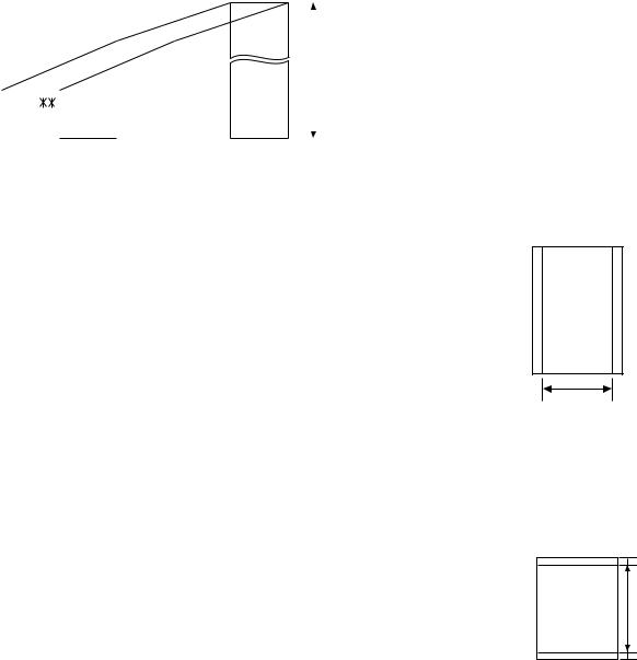
6.Readable Width & Length
The readable width and length of a document are slightly smaller than the actual document size.
Note that characters or graphics outside the effective document scanning range will not be read.
• Readable width
8.1" (206mm), max.
Readable width
• Readable length
This is the length of the document sent minus 0.2" (5mm) from the top and bottom edges.
0.2"(5mm)
Readable length
0.2"(5mm)
1 – 3
UX-510UA
FO-1470U
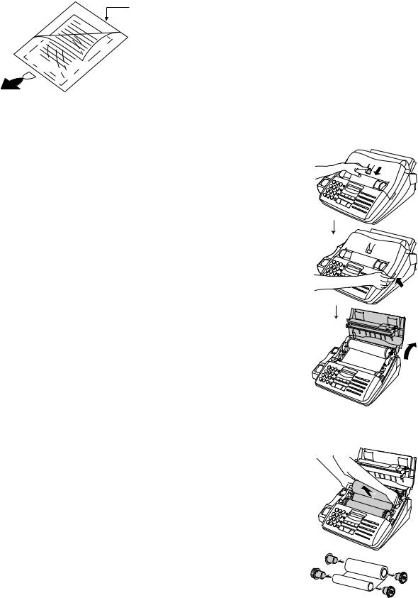
7. Use of Document Carrier Sheet
A document carrier sheet must be used for the following documents.
•Those with tears.
•Those smaller than size 5.83" (W) x 5.04" (L) (148 mm (W) x 128 mm (L)).
•Carbon-backed documents
Make print straight across paper E.G.
Place the document carrier in the document feeder with the clear film side down
Direction of insertion
NOTE: To transmit a carbon-backed document, insert a white sheet of paper between the carbon back of the document and the document carrier.
•Those containing an easily separable writing substance (e.g., tracking paper written on with a soft, heavy lead pencil).
NOTES: • When using the document carrier, carefully read the instructions written on the back.
•If the document carrier is dirty, clean it with a soft, moist cloth, and then dry it before using for transmission.
•Do not place more than one document in the carrier at a time.
[4]Installation
1. Site selection
Take the following points into consideration when selecting a site for this model.
ENVIRONMENT
•The machine must be installed on a level surface.
•Keep the machine away from air conditioners, heaters, direct sunlight, and dust.
•Provide easy access to the front, back, and sides of the machine. In particular, keep the area in front of the machine clear, or the original document may jam as it comes out after scanning.
•The temperature should be between 5° and 35°C.
•The humidity should be between 30% and 85% (without condensation).
ELECTRICITY
AC 120V, 60Hz, grounded (3-prong) AC outlet is required.
Caution!
•Connection to a power source other than that specified will cause damage to the equipment and is not covered under the warranty.
•If your area experiences a high incidence of lightning or power surges, we recommend that you install a surge protector for the power and telephone lines. Surge protectors can be purchased at most telephone speciality stores.
If the machine is moved from a cold to a warm place...
Condensation may form on the reading glass if machine is moved from a cold to a warm place, this will prevent proper scanning of documents for transmission. Turn on the power and wait approximately 2 hours before using machine.
TELEPHONE JACK
A standard RJ11C telephone jack must be located near the machine. This is the telephone jack commonly used in most homes and offices.
•Plugging the fax machine into a jack which is not a RJ11C jack may result in damage to the machine or your telephone system. If you do not know what kind of jack you have, or needed to have one installed, contact the telephone company.
2. Loading the imaging film (UX-15CR/FO-15CR)
Your fax uses a roll of imaging film to create printed text and images. The print head in the fax applies heat to the imaging film to transfer ink to the paper. Follow the steps below to load or replace the film.
•The initial starter roll of imaging film included with your fax can print about 60 letter-size pages.
•When replacing the film, use a roll of Sharp UX-15CR/FO-15CR imaging film. One roll can print about 500 letter-size pages.
1Press the release marked OPEN and open the print compartment cover.
• Caution! The printing head (the strip of metal on the underside of the cover) applies heat to the printing film. It may be hot if a document has just been printed.
2If you are replacing the imaging film, take the old film out of the printing compartment and remove the three (3) green gears and the green flange from the ends of the spools.
DO NOT DISCARD THE GREEN GEARS AND THE GREEN FLANGE!
1 – 4

3Take the new film out of its package, and insert two of the gears provided with the fax into the ends of the spool with film. Make sure that the two tabs on the gears fit properly into the slots in the ends of the spool.
• Do not yet remove the band which holds the spools together.
2 tabs
4Hold the empty spool so that the end with only one slot is on the left, and lower the spools into the front of the printing compartment. The gears in the ends of the spool with film should fit into the slots on each side of the printing compartment.
5Cut the band which holds the spools together with scissors, and remove it. Insert the remaining gear into the right end of the empty spool and the flange into the left end of the empty spool. Make sure the tabs on the gear and the flange fit into the slots in the ends of the spool (the gear has two tabs and the flange has one tab).
1 tab
Flange
2 tabs
Gear
6Pull the empty spool toward the back of the compartment, unwinding the film as you pull.
UX-510UA
FO-1470U
7Insert the empty spool into the back of the compartment so that the gear and the flange fit into the slots on the sides of the compartment.
• Make sure that the gear engages with the gear below it.
8Wind the film slightly (rotate the gear on the right side of the empty spool) so that there is no slack in the film. Make sure that both edges of the film wind onto the spool evenly.
9Close the print compartment cover, making sure it clicks into place.
• Caution! Close the cover slowly to make sure it doesn’t pinch your fingers.
FLoad paper in the paper tray and then press the following keys to initialize the film.
Note: Paper must be loaded before the film can be initialized. To load paper, see Loading the Printing Paper.
FUNCTION |
6 |
Display shows: |
START |
|
INITIALIZE FILM |
|
|
|
|
|
When to replace the imaging film
Replace the imaging film when the display shows:
FILM END
Use the following imaging film, which is available from your dealer or retailer: Sharp UX-15CR/FO-15CR Imaging Film
• Caution! The text of documents printed with the imaging film is visible on the used film. If confidential information has been printed, dispose of the film appropriately.
1 – 5
UX-510UA
FO-1470U
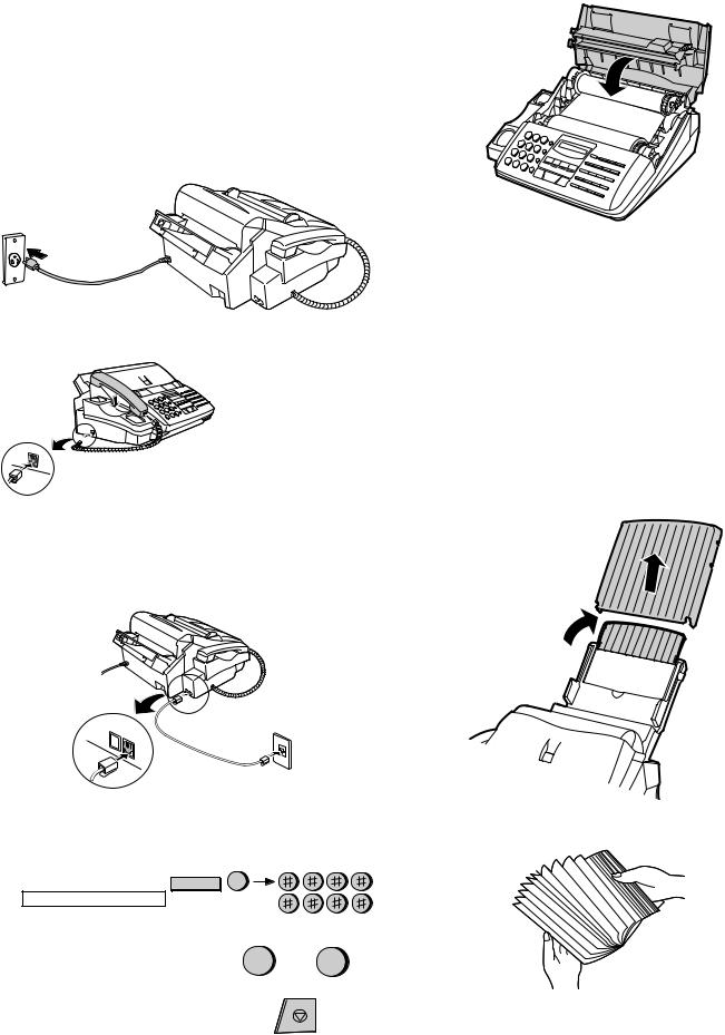
3. Assembly and connections
1Plug the power cord into a 120V, 60Hz, grounded(3-prong) outlet.
•Caution: Do not plug the power cord into any other kind of outlet. This will damage the machine and is not covered under the warranty.
•The machine does not have a power on/off switch, so the power is turned on and off by simply plugging in or unplugging the power cord.
Note: If your area experiences a high incidence of lightning or power surges, we recommend that you install surge protectors for the power and telephone lines. Surge protectors can be purchased at most telephone specialty stores.
4Insert the paper tray into the back of the fax as shown.
2Connect the handset as shown and place it on the handset rest.
Make sure the handset cord goes into the unmarked jack on the side of the machine!
Use the handset to make ordinary phone calls, or to transmit and receive faxes manually.
3Insert one end of the line cord into the jack on the back of the machine marked TEL.LINE. Insert the other end into a standard (RJ11C) single-line wall telephone jack.
Be sure to insert the line into the TEL.LINE jack.
Do not insert into the TEL.SET jack.
4. Loading printing paper
The paper tray holds the paper on which received documents and copies are printed. Up to 200 sheets of letter or legal paper from
16 to 20 lbs. (60 to 75 g/m2) can be loaded in the tray. Less sheets can be loaded when using heavier paper. The maximum allowed paper weight is 24 lbs. (90 g/m2).
Note: When receiving or copying documents, do not allow more than 100 pages to collect in the received documents outlet. Otherwise, the outlet may become obstructed, causing paper jams.
• Caution! Do not use the blank side of paper that has already been printed on.
1Remove the paper cover if it is on the paper tray.
•If you are going to load legal size paper, flip up the paper tray extender.
TEL
SET. TEL
LINE.
Note: The fax machine is set for tone dialing. If you are on a pulse dial line, you must set the fax machine for pulse dialing.
Press the keys on the operation panel as follows:
1. Press these keys:
The display will show: |
FUNCTION |
4 |
DIAL MODE
2. Press 1 to select tone dialing, or 2 |
TONE |
PULSE |
|
1 |
or 2 |
||
to select pulse dialing. |
|||
|
|||
|
|
STOP |
3. Press the STOP key to return to the date and time display.
2Fan the paper, and then tap the edge against a flat surface to even the stack.
1 – 6

3Pull the paper release plate toward you and insert the stack of paper into the tray, print side down.
•If paper remains in the tray, take it out and combine it into a single stack with the new paper before adding the new paper.
4Replace the paper cover on the paper tray.
•Important: Be sure to replace the paper cover before you put back the paper release plate down.
Note: If the display shows the following alternating messages when making a copy or receiving a fax, check the paper tray. If the tray is empty, add paper and then press the START key. If there is paper, make sure it is inserted correctly and then press the START key.
SET PAPER &
− |
− |
PRESS START KEY
UX-510UA
FO-1470U
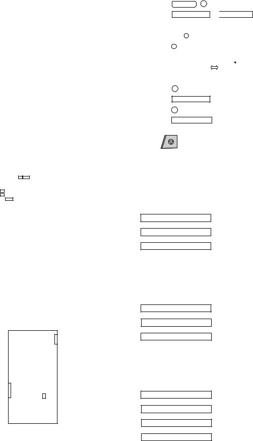
5The fax has been set at the factory to scale the size of received faxes to letter size paper. If you have loaded legal paper, you must change the paper size setting to legal. Press these keys:
|
FUNCTION |
6 |
The display will show: PAPER SIZE SET |
|
|
Press 1 to select LETTER, 2 to select LEAGAL. |
LETTER |
LEAGAL |
|
1 |
or 2 |
The display will show: COPY CUT-OFF |
|
STOP |
|
|
Press the STOP key to return to the date and time display.
6Your fax has been set at the factory to print at normal contrast.
Depending on the type of paper you have loaded, you may find that you obtain better print quality by changing the setting to LIGHT.
Press these keys:
|
FUNCTION |
|
The display will show: PRINT CONTRAST |
6 |
|
Press 1 to select NORMAL or 2 to select LIGHT. |
NORMAL |
LIGHT |
|
1 |
or 2 |
The display will show: PAPER SIZE SET |
|
STOP |
|
|
|
Press the STOP key to return to the date and time display.
5. Clearing paper jams
If a document doesn’t feed properly during transmission or copying, or DOCUMENT JAMMED appears in the display, first try pressing the START key. If the document doesn’t feed out, open the operation panel
(grasp the front edge at the "PANEL RELEASE" mark and pull up) and pull it out gently.
1Press the release marked OPEN and open the print compartment cover.
• Caution! The printing head (the strip of metal on the underside of the frame) applies heat to the imaging film. It may be hot if a document has just been printed.
1 – 7

UX-510UA
FO-1470U
2Remove the imaging film from the printing compartment and set it on a sheet of paper.
3Gently pull the jammed paper out of the printing compartment.
4Replace the imaging film, making sure that the flange goes into the rear slot on the left side of the printing compartment. Also, make sure that the right, rear gear engages with the gear below it.
5Wind the film slightly (rotate the gear on the right side of the rear spool) so that there is no slack in the film. Make sure that both edges of the film wind onto the spool evenly.
6Close the print compartment cover, making sure it clicks into place.
• Caution! Close the cover slowly to make sure it doesn’t pinch your fingers.
1 – 8
[5] Quick reference guide
ENTERING YOUR NAME AND NUMBER
1. |
Press: FUNCTION |
3 |
Display shows: OWN NUMBER SET
START
2.Press: 
3.Enter your fax number (max. of 20 digits) by pressing the number keys.
♦To insert a space between digits, press the # key.
♦If you make a mistake, press the SPEED DIAL key to backspace and clear the mistake.
START
4.Press: 
5.Enter your name by pressing the appropriate number keys as shown below. ♦ To enter two letters in succession that require the same key, press the SPEAKER
key after entering the first letter.
SPACE = |
J = |
T = |
A = |
K = |
U = |
B = |
L = |
V = |
C = |
M = |
W = |
|
|
|
D = |
N = |
X = |
E = |
O = |
Y = |
F = |
P = |
Z = |
G = |
Q = |
|
|
|
|
H = |
R = |
|
I = |
S = |
|
•To change case, press the REDIAL key.
Press # or  to scroll through symbols and special characters.
START STOP
6. When finished, press:
SETTING THE DATE AND TIME
1. Press: FUNCTION  3
3
Display shows: DATE & TIME SET
START
2.Press: 
3.Enter two digits for the month (01 to 12).
4.Enter two digits for the day (01 to 31).
5.Enter four digits for the year (Ex: 2000).
6.Enter two digits for the hour (01 to 12) and two digits for the minute (00 to 59).
7.Press  for A.M. or # for P.M.
START STOP
8. When finished, press:
STORING AND CLEARING AUTO DIAL NUMBERS
1. |
Press: FUNCTION |
3 |
Display shows: FAX/TEL # MODE
2.Press 1 to store a number or 2 to clear a number.
3.Enter a 2-digit number (from "01" to "99") by pressing the number keys. This will be the Speed Dial number. (If you are clearing a number, go to Step 7.)
4.Enter the full fax/telephone number.
START
5.Press: 
6.Enter the name of the location by pressing number keys (Refer to the letter entry table in ENTERING YOUR NAME AND NUMBER.)
START STOP
7. Press:
UX-510UA
FO-1470U
SENDING FAXES
Place your document (up to 20 pages) face down in the document feeder.
Normal Dialing
SPEAKER
1. Lift the handset or press:
2.Dial the fax number.
3.Wait for the reception tone (if a person answers, ask them to press their Start key).
START
4. Press:
Rapid Key Dialing
Press the appropriate Rapid Key (if the Rapid Key is from 19 to 36, press the SHIFT key first).
Transmission will begin automatically.
Speed Dialing
SPEED
1.Press: DIAL
2.Enter 2-digit Speed Dial number.
START
3. Press:
RECEIVING FAXES
Press the RECEPTION MODE key until the appears in the display points to the desired reception mode.
TEL FAX
NOV 05 10:30 
RECEPTION
A.M.
MODE
TEL FAX
NOV 05 10:30
A.M.
TEL FAX
NOV 05 10:30
A.M.
FAX mode: The fax machine automatically answers on four rings and receives the incoming document.
TEL mode:
START
Beep
RECEIVING
A.M. mode: Select this mode when an answering machine is connected to the fax and the answering machine is turned on.
1 – 9

UX-510UA
FO-1470U
M E M O
1 – 10
CHAPTER 2. ADJUSTMENTS
[1] Adjustments
General
Since the following adjustments and settings are provided for this model, make adjustments and/or setup as necessary.
1. Adjustments
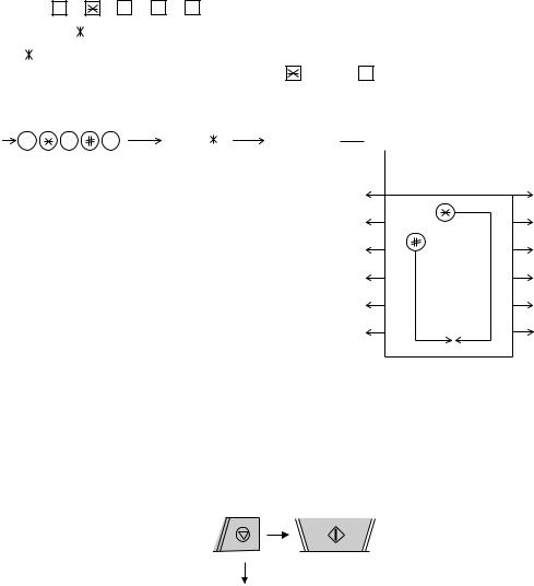
Adjustments of output voltage (FACTORY ONLY)
1.Install the power supply unit in the machine.
2.Set the recording paper and document.
3.When the document is loaded, power is supplied to the output lines. Confirm that outputs are within the limits below.
Output voltage settings
|
|
|
|
|
|
|
|
|
|
|
|
|
|
|
|
|
|
|
|
|
|
|
|
|
|
|
|
|
|
|
|
|
|
|
|
|
|
|
|
|
|
POWER |
|
|
|
|
|
|
|
|
|
|
|
|
|
|
|
|
|
|
|
|
|
SUPPLY |
|
|
|
|
|
|
|
|
|
|
CNTH |
CNPW |
|
|
|
|
PWB |
||||||
|
|
|
|
|
|
|
|
|
|
|
|
|
|
|
|
|
|
|
|
|
|
|
|
|
|
|
|
|
|
|
|
|
|
|
|
|
|
|
|
|
|
|
|
|
|
|
|
|
|
|
|
|
|
|
|
|
|
|
|
|
|
|
|
|
|
TEL/LIU |
|
|
|
CONTROL |
|
|
|
|
|
|
|
|
|
||||||||
PWB |
|
|
|
PWB |
|
|
|
|
|
|
|
|
|
||||||||
CNLIUA |
|
|
|
|
|
|
CNLIUA |
|
|
CNMT |
|
|
|
|
|||||||
|
|
|
|
|
|
|
CNLED |
|
|
|
|
|
|
||||||||
|
|
|
|
|
|
|
CNSP |
|
|
|
|
|
|
|
|
|
|||||
|
|
|
|
|
|
|
CNCSW |
|
|
|
|
|
|
|
|
|
|||||
|
|
|
|
CNCCD |
|
|
|
|
|
CNPN |
|
|
|
|
|||||||
|
|
|
|
|
|
|
|
|
|
|
|
|
|||||||||
Output |
Voltage limits |
|
|
+5V |
4.75V 5.25V |
+24V |
23.3V 24.7V |
Connector |
|
No. |
CNPW |
Pin No. |
|
1 |
+24V |
2 |
+24V |
3 |
MG |
4 |
MG |
5 |
+5V |
6 |
DG |
2. IC protectors replacement
ICPs (IC Protectors) are installed to protect the motor driver circuit.
ICPs protect various ICs and electronic circuits from an overcurrent condition.
The location of ICPs are shown below:
CONTROL
PWB (TOP SIDE)
CNLIUA FU100
(1)FU100 (KAB2402) is installed in order to protect IC’s from an overcurrent generated in the motor drive circuit. If FU100 is open, replace it with a new one.
UX-510UA
FO-1470U
3. Settings
(1) Dial mode selector
DIAL mode (Soft Switch No. SWB4 DATA No. 3)
(step 1) Select "OPTION SETTING".
KEY : FUNCTION 4
DISPLAY: OPTION SETTING 
 PRESS
PRESS  OR #
OR #
(step 2) Select "DIAL MODE".
KEY: |
Push # until " |
DIAL MODE |
" is |
|
|
|
||
|
indicated because the number of |
|
|
|
||||
|
# s changes by the model. |
|
Cursor |
|||||
|
|
|
|
|
|
|
When initially registering, |
|
|
|
|
|
|
|
|
the mode shows 1=TONE. |
|
|
|
|
|
|
|
|
When registering again, the |
|
|
|
|
|
|
|
|
mode which was registered |
|
|
|
|
|
|
|
|
formerly is shown. |
|
|
|
|
|
|
|
|||
DISPLAY: |
DIAL MODE |
|
1=TONE, 2=PULSE |
|
||||
(step 3) Select, using "1" or "2".
KEY: 1
DISPLAY: TONE SELECTED
KEY: 2
DISPLAY: PULSE SELECTED
(step 4) End, using the "STOP" key.
KEY: STOP
4. Volume adjustment
You can adjust the volume of the speaker and ringer using the UP and
DOWN keys.
(1) Speaker
1Press the SPEAKER key.
2Press the UP or DOWN key.
Display:
SPEAKER: HIGH
↔
SPEAKER: MIDDLE
↔
SPEAKER: LOW
3When the display shows the desired volume level, press the SPEAKER key to turn off the speaker.
(2) Handset
1Lift the handset.
2Press the UP or DOWN key.
Display:
RECEIVER: HIGH
↔
RECEIVER: MIDDLE
↔
RECEIVER: LOW
3When the display shows the desired volume level, replace the handset.
(3) Ringer
1Press the UP or DOWN key. (Make sure the SPEAKER key has not been pressed and the handset is not lifted.)
Display:
RINGER: HIGH
↔
RINGER: MIDDLE
↔
RINGER: LOW
↔
RINGER OFF: OK?
The ringer will ring once at the selected level, then the date and time will reappear in the display.
2If you selected RINGER OFF: OK?, press the START key.
2 – 1
UX-510UA
FO-1470U
[2] Diagnostics and service soft switch
1. Operating procedure
(1) Entering the diagnostic mode
Press |
FUNC |
→ 9 → |
→ 8 |
→ # → 7 , and the following display will appear. |
|
|
|||||||||||||||||||||
|
|
|
|
|
|
|
|
|
|
|
|
|
|
|
|
|
|
|
|
|
|
|
|
|
|||
|
ROM Ver. FPS0 |
|
After 2 sec: |
DIAG MODE |
|
|
|
|
|
|
|
|
|
|
|
|
|
|
|
|
|||||||
|
FPS0 |
|
|
|
|
|
|
|
|
|
|
|
|
|
|
|
|
|
|
|
|
|
|
|
|
|
|
|
|
|
|
|
|
|
|
|
|
|
|
|
|
|
|
|
|
|
|
|
|
|
|
|
|
||
Then press the |
START |
key. Select the desired item with the |
key or the |
# key or select with the rapid key. Enter the mode with the START key. |
|||||||||||||||||||||||
(Diag∙specifications) |
|
|
|
|
|
|
|
|
|
|
|
|
|
|
|
|
|
|
|
|
|
||||||
|
|
|
|
|
|
|
|
|
|
|
|
|
|
|
|
|
|
|
|
|
|
|
|
|
|||
FUNC |
|
9 |
|
8 |
|
7 |
|
|
FPS0 |
|
|
DIAG MODE |
|
|
START |
|
|
|
|
|
|
|
|||||
|
|
|
|
|
|
|
|
|
|
|
|
|
|
|
|
|
|
|
|
|
|
Entry data receive |
|||||
|
|
|
|
|
|
|
|
Soft switch mode |
|
START |
|
1 |
|
|
|
|
12 |
|
START |
||||||||
|
|
|
|
|
|
|
|
|
|
|
|
|
|
|
|
|
|
|
|
|
|
|
|
|
|
|
|
|
|
|
|
|
|
|
|
ROM & RAM check |
|
START |
|
2 |
|
|
|
11 |
|
START |
Entry data send |
||||||||
|
|
|
|
|
|
|
|
|
|
|
|
|
|
|
|
|
|
|
|
|
|
|
|
|
|
|
Auto feeder mode |
|
|
|
|
|
|
|
|
Aging mode |
|
START |
|
3 |
|
|
|
|
|
10 |
|
START |
|||||||
|
|
|
|
|
|
|
|
|
|
|
|
|
|
|
|
|
|
|
|
|
|
||||||
|
|
|
|
|
|
|
|
Panel key test |
|
START |
|
4 |
|
|
|
|
|
9 |
|
START |
All black mode |
||||||
|
|
|
|
|
|
|
|
|
|
|
|
|
|
|
|
|
|
|
|
|
|
||||||
|
|
|
|
|
|
|
|
Check pattern |
|
START |
|
5 |
|
|
|
|
8 |
|
START |
CCD adjust mode |
|||||||
|
|
|
|
|
|
|
|
|
|
|
|
|
|
|
|
|
|
|
|
|
Memory clear |
||||||
|
|
|
|
|
|
|
|
Signal send mode |
|
START |
|
6 |
|
|
|
|
7 |
|
START |
||||||||
If the diag mode cannot be set, repeat the diag mode operation, performing the following operation.
After the power is turned on and "WAIT A MOMENT" is indicated, press the STOP key.
STOP |
START |
KEY |
KEY |
|
|
"Power ON" +
Memory clear (Work + Backup)
In relation with the process response (request from Production Engineering) "WAIT A MOMENT" clock indication may appear depending on STOP key timing. If the STOP key is held down, "MEMORY CLEAR?" appears.
2. Diagnostic items
ITEM |
DIRECT |
Contents |
Function |
|
No. |
key |
|||
|
|
|||
|
|
|
|
|
1 |
1 |
SOFT SWITCH MODE |
Soft switches are displayed and changed. List can be output. |
|
|
|
|
|
|
2 |
2 |
ROM & RAM CHECK |
ROM is sum-checked, and RAM is matched. Result list is output. |
|
|
|
|
|
|
3 |
3 |
AGING MODE |
10 sheets of check patterns are output every 5 minutes per sheet. |
|
|
|
|
|
|
4 |
4 |
PANEL KEY TEST |
Panel keys are tested. Result list is output. |
|
|
|
|
|
|
5 |
5 |
CHECK PATTERN |
Check pattern is output. |
|
|
|
|
|
|
6 |
6 |
SIGNAL SEND MODE |
Various signals of FAX communication are output. |
|
|
|
|
|
|
7 |
7 |
MEMORY CLEAR |
Back-up memory is cleared, and is set at delivery. |
|
|
|
|
|
|
8 |
8 |
CCD ADJUST MODE |
Optical system is adjusted. |
|
|
|
|
|
|
9 |
9 |
ALL BLACK PRINT |
To check the print head, whole dots are printed over the interval of 2 m. |
|
|
|
|
|
|
10 |
10 |
AUTO FEEDER MODE |
Insertion and discharge of document are tested. |
|
|
|
|
|
|
11 |
11 |
ENTRY DATA SEND |
Registered content is sent. |
|
|
|
|
|
|
12 |
12 |
ENTRY DATA RECEIVE |
Registered content is received, and its list is output. |
|
|
|
|
|
2 – 2

3. Diagnostic items description
3. 1. Soft switch mode
Used to change the soft switch settings.
The soft switch which is stored internally is set by using the keys.
The available soft switches are SW-A1 to SW-N3.
The content of soft switches is shown in page 2-5 to 2-18.
The contents are set to factory default settings.
3. 2. ROM & RAM check
ROM executes the sum check, and RAM executes the matching test.
The result will be notified with the number of short sounds of the buzzer as well as by printing the ROM & RAM check list.
Number of short sounds of buzzer 0 → No error
1 → ROM error
2 → RAM error (32Kbyte)
3. 3. Aging mode
If any document is first present, copying will be executed sheet by sheet.
If no document is present, the check pattern will be printed sheet by sheet. This operation will be executed at a rate of one sheet per 5minutes, and will be ended at a total of 10 sheets.
3. 4. Panel key test
This mode is used to check whether each key operates properly or not. Press the key on the operation panel, and the key will be displayed on the display.Therefore, press all keys. At this time, finally press the STOP key.
When the STOP key is pressed, the keys which are not judged as "pressed" will be printed on the result list.
•LED part of the contact image sensor (CIS) is kept on during the term from when "START" of the panel test mode to end with the STOP key.
3. 5. Check pattern
This mode is used to check the state of the printing head. It is ended with the following pattern printed on one printing sheet.
1Longitudinal stripe 2 Approx. 30 mm
2 black dots and 2 white dots are repeatedly progressed on one line.
2 Full black |
Approx. 30 mm |
1
2
UX-510UA
FO-1470U
3. 6. Signal send mode
This mode is used to send various signals to the circuit during FAX communication. Every push of START key sends a signal in the following sequence. Moreover, the signal sound is also output to the speaker when the line monitor of the soft switch is on.
[1]No signals (CML ON)
[2]14400BPS (V.33)
[3]12000BPS (V.33)
[4]14400BPS (V.17)
[5]12000BPS (V.17)
[6]9600BPS (V.17)
[7]7200BPS (V.17)
[8]9600BPS (V.29)
[9]7200BPS (V.29)
[10]4800BPS (V27ter)
[11]2400BPS (V27ter)
[12]FLAG
[13]2100Hz
[14]1100Hz
3. 7. Memory clear
This mode is used to clear the backup memory and reset to the default settings.
3. 8. CCD adjust mode
This mode is used to adjust the optical system. Since the copy is function performed, set the original. To abort the copy operation, press the STOP key. To restart press the START key. When the copy is completed or when the STOP key is pressed in the interruption state, exit from this mode occurs.
3. 9. All black print
This mode is used to check the state of the printing head and intentionally overheat it. Whole dots are printed over the interval of 2 m. If it is overheated or the printing sheet is jammed, press STOP key for the end.
3. 10. Auto feeder mode
In this mode, a document is inserted and discharged to check the auto feed function.
After this mode is started, set a document, and the document feed will be automatically tested.
3. 11. Entry data send
This mode is used to send the registered data to the other machine and make the other machine copy the registered content.
Before sending in this mode, it is necessary to set the other machine at the entry data receive mode.
The following, information will be sent to the remote machine:
1.Telephone list data
2.Sender register data
3.Optional setting content
4.Soft switch content
5.Junk fax number list
6.Timer reservation data (only on the model which timer reservation is possible)
7.Recording setting list data
2 – 3
UX-510UA
FO-1470U
3. 12. Entry data receive
In this mode, the registered data sent from the other machine is received and the received data is registered in the machine. When this mode is used for receiving, the other machine must be in the entry data send mode.
After receiving is completed, the following lists are printed.
1.Telephone list data
2.Sender register data (The passcode No. is also printed if the polling function is provided.)
3.Optional setting list
4.Soft switch content
5.Junk fax number list
6.Timer reservation list (only model which timer communication is possible)
7.Recording setting list data
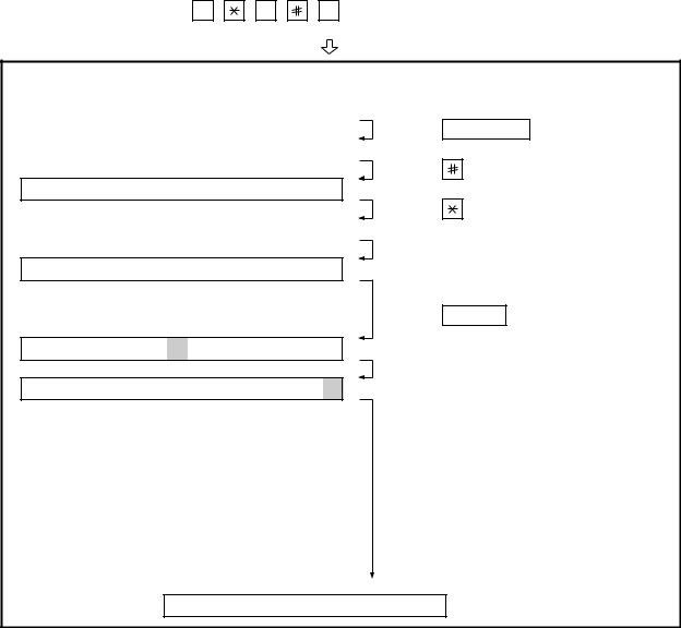
4.How to make soft switch setting
To enter the soft switch mode, press the following key entries in sequence.
Press |
|
|
|
|
|
|
|
|
FUNCTION |
9 |
8 |
7 |
START |
|
START |
|
|
|
|
|
|
|
|
|
|
|
DATA No. |
1 2 |
3 |
4 5 6 7 8 |
|||||
|
|
|
||||||
S F T SW-A1 = |
0 |
0 0 0 0 0 0 0 |
||||||
|
|
|
|
|
|
|
|
|
S F T SW-A1 = |
1 |
0 |
0 |
0 0 |
0 |
0 0 |
||
|
|
|
|
|
|
|||
S F T SW-A1 = 1 |
|
0 |
0 |
0 0 |
0 |
0 0 |
||
|
|
|
|
|
|
|
|
|
S F T SW-A1 = |
1 |
0 |
0 |
0 0 |
0 |
0 0 |
||
|
|
|
|
|
|
|
||
S F T SW-A1 = 1 |
0 |
0 |
0 0 |
0 |
0 |
0 |
||
S F T SW-A2 = 0 0 0 0 0 0 0 0
S F T SW-N3 = 0 0 0 0 0 0 0 0
Press FUNCTION key.
Press key.
Press key.
Bit1 - 8 are set.
Press START key during setting.
Soft SW-A2 - SW-N3 are set.
 To finish the settings halfway between SW-A1 and SW-N3, press the STOP key. In this case, the setting being done to the SW No. on display will be nullified while settings done to the preceding SW Nos. remain in effect.
 When the COPY key is pressed, the contents of soft switches are printed.
The soft switch mode is terminated.
2 – 4
UX-510UA
FO-1470U
5. Soft switch description
• Soft switch
SW |
|
DATA |
ITEM |
|
|
|
|
|
|
Switch setting and function |
|
|
|
|
|
Initial |
Remarks |
||||||||||
|
|
|
|
|
|
|
|
|
|
|
|
||||||||||||||||
NO. |
|
NO. |
|
|
|
|
1 |
|
|
|
|
|
|
|
|
|
|
0 |
|
|
|
|
|
setting |
|||
|
|
|
|
|
|
|
|
|
|
|
|
|
|
|
|
|
|
|
|
|
|
||||||
|
|
|
|
|
|
|
|
|
|
|
|
|
|
|
|
|
|
|
|
|
|
|
|
|
|
|
|
|
|
1 |
Protect from echo |
No |
|
|
|
|
|
|
|
|
|
|
|
|
Yes |
|
|
|
|
|
|
|
|
0 |
|
|
|
|
|
|
|
|
|
|
|
|
|
|
|
|
|
|
|
|
|
|
|
|
|
|
|
|
|
|
|
2 |
Forced 4800 BPS reception |
Yes |
|
|
|
|
|
|
|
|
|
|
|
|
No |
|
|
|
|
|
|
|
|
0 |
|
|
|
|
|
|
|
|
|
|
|
|
|
|
|
|
|
|
|
|
|
|
|
|
|
|
|
|
|
|
|
3 |
Footer print |
Yes |
|
|
|
|
|
|
|
|
|
|
|
|
No |
|
|
|
|
|
|
|
|
0 |
|
|
|
|
|
|
|
|
|
|
|
|
|
|
|
|
|
|
|
|
|
|
|
|
|
|
|
|
|
|
|
4 |
Length limitation of copy/send/receive |
No limit |
|
|
|
|
|
|
|
|
|
Copy/send: 1m |
|
|
|
|
|
0 |
|
||||||
SW |
|
|
|
|
|
|
|
|
|
|
|
|
|
|
|
|
Receive: 1.5m |
|
|
|
|
|
|
|
|||
|
|
|
|
|
|
|
|
|
|
|
|
|
|
|
|
|
|
|
|
|
|
|
|
|
|
|
|
|
5 |
CSI transmission |
No transmitted |
|
|
|
|
|
|
|
Transmitted |
|
|
|
|
|
|
0 |
|
||||||||
l |
|
|
|
|
|
|
|
|
|
|
|
|
|
|
|
||||||||||||
A1 |
|
6 |
DIS receive acknowledgement during G3 |
Twice |
|
|
|
|
|
|
|
|
|
NSF: Once |
|
|
|
|
|
|
0 |
|
|||||
|
|
|
|
|
|
|
|
|
|
|
|
|
|
|
|
|
|
||||||||||
|
|
|
transmission |
|
|
|
|
|
|
|
|
|
|
|
|
|
DIS: Twice |
|
|
|
|
|
|
|
|
||
|
|
|
|
|
|
|
|
|
|
|
|
|
|
|
|
|
|
|
|
|
|
|
|
|
|
|
|
|
|
7 |
Non-modulated carrier for V29 transmission |
Yes |
|
|
|
|
|
|
|
|
|
|
|
|
No |
|
|
|
|
|
|
|
|
0 |
|
|
|
|
modem |
|
|
|
|
|
|
|
|
|
|
|
|
|
|
|
|
|
|
|
|
|
|
|
|
|
|
|
|
|
|
|
|
|
|
|
|
|
|
|
|
|
|
|
|
|
|
|
|
|
|
|
|
|
|
8 |
EOL detect timer |
25 s |
|
|
|
|
|
|
|
|
|
|
|
|
13 s |
|
|
|
|
|
|
|
|
0 |
|
|
|
|
Modem speed |
V.33 |
|
|
|
|
|
V.17 |
|
|
|
V.29 |
|
|
V.27 ter |
|
|
||||||||
|
|
|
|
14400 |
12000 |
14400 |
12000 |
|
9600 |
7200 |
9600 |
7200 |
|
4800 |
|
2400 |
|
|
|||||||||
|
|
|
|
|
|
|
|
|
|
|
|
|
|
|
|
|
|
|
|
|
|
|
|
|
|
|
|
|
|
1 |
|
0 |
|
0 |
|
1 |
|
1 |
|
|
1 |
|
1 |
0 |
0 |
|
0 |
|
0 |
1 |
|
||||
|
|
|
|
|
|
|
|
|
|
|
|
|
|
|
|
|
|
|
|
|
|
|
|
|
|
|
|
|
|
2 |
|
1 |
|
1 |
|
0 |
|
0 |
|
|
0 |
|
0 |
0 |
0 |
|
0 |
|
0 |
0 |
|
||||
|
|
|
|
|
|
|
|
|
|
|
|
|
|
|
|
|
|
|
|
|
|
|
|
|
|
|
|
SW |
|
3 |
|
0 |
|
1 |
|
0 |
|
1 |
|
|
0 |
|
1 |
0 |
1 |
|
1 |
|
0 |
0 |
|
||||
|
|
|
|
|
|
|
|
|
|
|
|
|
|
|
|
|
|
|
|
|
|
|
|
|
|
|
|
|
4 |
|
0 |
|
0 |
|
0 |
|
0 |
|
|
1 |
|
1 |
1 |
1 |
|
0 |
|
0 |
0 |
|
|||||
l |
|
|
|
|
|
|
|
|
|
|
|
||||||||||||||||
A2 |
|
5 |
Sender’s information transmit |
No |
|
|
|
|
|
|
|
|
|
|
|
|
Yes |
|
|
|
|
|
|
|
|
0 |
|
|
|
|
|
|
|
|
|
|
|
|
|
|
|
|
|
|
|
|
|
|
|
|
|||||
|
|
|
|
|
|
|
|
|
|
|
|
|
|
|
|
|
|
|
|
|
|
|
|
|
|
|
|
|
|
6 |
Reserved |
|
|
|
|
|
|
|
|
|
|
|
|
|
|
|
|
|
|
|
|
|
|
0 |
|
|
|
|
|
|
|
|
|
|
|
|
|
|
|
|
|
|
|
|
|
|
|
|
|||||
|
|
7 |
Communication error treatment in RTN |
No communication error |
|
|
|
Communication error |
|
|
0 |
|
|||||||||||||||
|
|
|
sending mode (reception) |
|
|
|
|
|
|
|
|
|
|
|
|
|
|
|
|
|
|
|
|
|
|
|
|
|
|
|
|
|
|
|
|
|
|
|
|
|
|
|
|
|
|
|
|
|
|
|
|
|
|
|
|
|
|
8 |
CNG transmission |
No |
|
|
|
|
|
|
|
|
|
|
|
|
Yes |
|
|
|
|
|
|
|
|
0 |
|
|
|
|
CED tone signal interval |
|
|
|
|
|
1000ms |
|
|
750ms |
|
500ms |
|
|
75ms |
|
|
||||||||
|
|
|
|
|
|
|
|
|
|
|
|
|
|
|
|
|
|
|
|
|
|
|
|
|
|
|
|
|
|
1 |
|
|
No. 1 |
|
|
1 |
|
|
|
|
|
1 |
|
|
0 |
|
|
|
0 |
0 |
|
||||
|
|
|
|
|
|
|
|
|
|
|
|
|
|
|
|
|
|
|
|
|
|
|
|
|
|
|
|
|
|
2 |
|
|
No. 2 |
|
|
1 |
|
|
|
|
|
0 |
|
|
1 |
|
|
|
0 |
0 |
|
||||
|
|
|
|
|
|
|
|
|
|
|
|
|
|
|
|
|
|
|
|
|
|
|
|
|
|
|
|
SW |
|
3 |
MR coding |
No |
|
|
|
|
|
|
|
|
|
|
|
|
Yes |
|
|
|
|
|
|
|
|
0 |
|
|
|
|
|
|
|
|
|
|
|
|
|
|
|
|
|
|
|
|
|
|
|
|
|
|
|
|
|
l |
|
4 |
ECM mode |
No |
|
|
|
|
|
|
|
|
|
|
|
|
Yes |
|
|
|
|
|
|
|
|
0 |
OPTION |
A3 |
|
|
|
|
|
|
|
|
|
|
|
|
|
|
|
|
|
|
|
|
|
|
|
|
|
|
|
|
5 |
ECM MMR mode |
No |
|
|
|
|
|
|
|
|
|
|
|
|
Yes |
|
|
|
|
|
|
|
|
0 |
|
|
|
|
|
|
|
|
|
|
|
|
|
|
|
|
|
|
|
|
|
|
|
|
|
|||||
|
|
|
|
|
|
|
|
|
|
|
|
|
|
|
|
|
|
|
|
|
|
|
|
|
|
|
|
|
|
6 |
Reserved |
|
|
|
|
|
|
|
|
|
|
|
|
|
|
|
|
|
|
|
|
|
|
0 |
|
|
|
|
|
|
|
|
|
|
|
|
|
|
|
|
|
|
|
|
|
|
|
|
|
|
|
|
|
|
|
7 |
Reserved |
|
|
|
|
|
|
|
|
|
|
|
|
|
|
|
|
|
|
|
|
|
|
0 |
|
|
|
|
|
|
|
|
|
|
|
|
|
|
|
|
|
|
|
|
|
|
|
|
|
|
|
|
|
|
|
8 |
Reserved |
|
|
|
|
|
|
|
|
|
|
|
|
|
|
|
|
|
|
|
|
|
|
0 |
|
|
|
|
|
|
|
|
|
|
|
|
|
|
|
|
|
|
|
|
|
|
|
|
|
|
|||
|
|
1 |
Signal transmission level |
|
|
|
|
Binary input |
|
|
|
|
|
|
|
|
|
|
0 |
|
|||||||
|
|
2 |
|
|
|
No. = |
16 |
8 |
4 |
|
2 |
|
1 |
|
|
|
|
|
|
|
|
|
1 |
|
|||
SW |
|
3 |
|
|
|
|
|
1 |
2 |
3 |
|
4 |
|
5 |
|
|
|
|
|
|
|
|
|
0 |
|
||
|
4 |
|
|
|
|
|
0 |
1 |
0 |
|
1 |
|
0 |
|
|
|
|
|
|
|
|
|
1 |
|
|||
l |
|
|
|
|
|
|
|
|
|
|
|
|
|
|
|
|
|
|
|||||||||
|
5 |
|
|
|
|
|
|
|
|
|
|
|
|
|
|
|
|
|
|
|
|
|
|
|
0 |
|
|
A4 |
|
|
|
|
|
|
|
|
|
|
|
|
|
|
|
|
|
|
|
|
|
|
|
|
|
||
|
|
|
|
|
|
|
|
|
|
|
|
|
|
|
|
|
|
|
|
|
|
|
|
|
|
|
|
|
|
6 |
Protocol monitor (error print) |
Printed at com. error |
|
|
|
|
|
Not printed |
|
|
|
|
|
|
0 |
|
|||||||||
|
|
|
|
|
|
|
|
|
|
|
|
|
|
|
|
|
|
|
|
|
|
|
|
|
|
|
|
|
|
7 |
Protocol monitor |
Yes |
|
|
|
|
|
|
|
|
|
|
|
|
No |
|
|
|
|
|
|
|
|
0 |
|
|
|
|
|
|
|
|
|
|
|
|
|
|
|
|
|
|
|
|
|
|
|
|
|
|
|
|
|
|
|
8 |
Line monitor |
Yes |
|
|
|
|
|
|
|
|
|
|
|
|
No |
|
|
|
|
|
|
|
|
0 |
|
|
|
|
Digital line equalization setting (Reception) |
|
|
|
|
|
|
7.2km |
|
|
3.6km |
|
1.8km |
|
|
0km |
|
|
|||||||
|
|
|
|
|
|
|
|
|
|
|
|
|
|
|
|
|
|
|
|
|
|
|
|
|
|
|
|
|
|
1 |
|
|
No. 1 |
|
|
1 |
|
|
|
|
|
1 |
|
|
0 |
|
|
|
0 |
0 |
|
||||
|
|
|
|
|
|
|
|
|
|
|
|
|
|
|
|
|
|
|
|
|
|
|
|
|
|
|
|
|
|
2 |
|
|
No. 2 |
|
|
1 |
|
|
|
|
|
0 |
|
|
1 |
|
|
|
0 |
1 |
|
||||
|
|
|
|
|
|
|
|
|
|
|
|
|
|
|
|
|
|
|
|
|
|
|
|
|
|
||
|
|
|
Digital line equalization setting |
|
|
|
|
|
|
7.2km |
|
|
3.6km |
|
1.8km |
|
|
0km |
|
|
|||||||
|
|
|
|
|
|
|
|
|
|
|
|
|
|
|
|
|
|
|
|
|
|
|
|
|
|
|
|
SW |
|
3 |
(Transmission) |
|
No. 3 |
|
|
1 |
|
|
|
|
|
1 |
|
|
0 |
|
|
|
0 |
0 |
|
||||
l |
|
4 |
|
|
No. 4 |
|
|
1 |
|
|
|
|
|
0 |
|
|
1 |
|
|
|
0 |
1 |
|
||||
A5 |
|
|
|
|
|
|
|
|
|
|
|
|
|
|
|
|
|
|
|
|
|
|
|
|
|
|
|
|
|
Digital cable equalizer setting (Reception |
|
|
|
|
|
|
|
|
7.2km |
|
|
|
|
0km |
|
|
|
|
|||||||
|
|
|
|
|
|
|
|
|
|
|
|
|
|
|
|
|
|
|
|||||||||
|
|
|
|
|
|
|
|
|
|
|
|
|
|
|
|
|
|
|
|
|
|
|
|
|
|
|
|
|
|
5 |
for Caller ID) |
|
No. 5 |
|
|
|
|
|
|
1 |
|
|
|
|
|
0 |
|
|
1 |
|
|||||
|
|
|
|
|
|
|
|
|
|
|
|
|
|
|
|
|
|
|
|
|
|
|
|
|
|
|
|
|
|
6 |
|
|
No. 6 |
|
|
|
|
|
|
1 |
|
|
|
|
|
0 |
|
|
1 |
|
|||||
|
|
|
|
|
|
|
|
|
|
|
|
|
|
|
|
|
|
|
|
|
|
|
|
|
|
|
|
|
|
7 |
Error criterion |
10 ~ 20 % |
|
|
|
|
|
|
|
|
|
|
5 ~ 10 % |
|
|
|
|
|
|
0 |
|
||||
|
|
|
|
|
|
|
|
|
|
|
|
|
|
|
|
|
|
|
|
|
|
|
|
|
|
|
|
|
|
8 |
Anti junk fax check |
Yes |
|
|
|
|
|
|
|
|
|
|
|
|
No |
|
|
|
|
|
|
|
|
0 |
OPTION |
|
|
|
|
|
|
|
|
|
|
|
|
|
|
|
|
|
|
|
|
|
|
|
|
|
|
|
|
2 – 5

UX-510UA
FO-1470U
SW |
|
DATA |
|
ITEM |
|
|
|
Switch setting and function |
|
|
Initial |
|
Remarks |
|||||||
|
|
|
|
|
|
|
|
|||||||||||||
NO. |
|
NO. |
|
|
1 |
|
|
|
|
|
|
|
|
0 |
|
setting |
|
|||
|
|
|
|
|
|
|
|
|
|
|
|
|
|
|
||||||
|
|
1 |
Auto gain control (MODEM) |
Enable |
|
|
|
|
|
|
|
Disable |
|
|
|
1 |
|
|
||
|
|
|
|
|
|
|
|
|
|
|
|
|
|
|
|
|
|
|
|
|
|
|
2 |
End Buzzer |
|
Yes |
|
|
|
|
|
|
|
No |
|
|
|
1 |
|
|
|
|
|
|
|
|
|
|
|
|
|
|
|
|
|
|
|
|
|
|
|
|
|
|
3 |
Disconnect the line when DIS is received in |
No |
|
|
|
|
|
|
|
Yes |
|
|
|
1 |
|
|
||
|
|
|
RX mode |
|
|
|
|
|
|
|
|
|
|
|
|
|
|
|
|
|
SW |
|
|
|
|
|
|
|
|
|
|
|
|
|
|
|
|
|
|
|
|
|
4 |
Equalizer freeze control (MODEM) |
On |
|
|
|
|
|
|
|
Off |
|
|
|
0 |
|
|
|||
l |
|
|
|
|
|
|
|
|
|
|
|
|
|
|||||||
|
|
|
|
|
|
|
|
|
|
|
|
|
|
|
|
|
|
|
|
|
|
5 |
Equalizer freeze control 7200BPS only |
No |
|
|
|
|
|
|
|
Yes |
|
|
|
0 |
|
|
|||
A6 |
|
|
|
|
|
|
|
|
|
|
|
|
|
|||||||
|
|
|
|
|
|
|
|
|
|
|
|
|
|
|
|
|
|
|
|
|
|
|
6 |
CNG transmission in manual TX mode |
Yes |
|
|
|
|
|
|
|
No |
|
|
|
1 |
|
|
||
|
|
|
|
|
|
|
|
|
|
|
|
|
|
|
|
|
|
|
|
|
|
|
7 |
Reserved |
|
|
|
|
|
|
|
|
|
|
|
|
|
|
0 |
|
|
|
|
|
|
|
|
|
|
|
|
|
|
|
|
|
|
|
|
|
|
|
|
|
8 |
Modem speed automatic fallback when RX |
Yes |
|
|
|
|
|
|
|
No |
|
|
|
0 |
|
|
||
|
|
|
level is under -40dBm |
|
|
|
|
|
|
|
|
|
|
|
|
|
|
|
|
|
|
|
1 |
Recall interval |
|
|
Binary input |
|
|
|
|
|
|
0 |
|
OPTION |
|||||
|
|
2 |
|
|
No. = |
8 |
4 |
2 |
1 |
|
|
|
|
|
|
|
1 |
|
|
|
|
|
3 |
|
|
|
1 |
2 |
3 |
4 |
|
|
|
|
|
|
|
0 |
|
|
|
SW |
|
4 |
|
|
|
0 |
1 |
0 |
1 |
|
|
|
|
|
|
|
1 |
|
|
|
l |
|
|
|
|
|
|
|
|
|
|
|
|
|
|
|
|
|
|
|
|
|
5 |
Recall times |
|
|
Binary input |
|
|
|
|
|
|
0 |
|
OPTION |
||||||
B1 |
|
|
|
|
|
|
|
|
|
|
||||||||||
|
|
|
|
|
|
|
|
|
|
|
|
|
|
|
|
|
|
|
|
|
|
|
6 |
|
|
No. = |
8 |
4 |
2 |
1 |
|
|
|
|
|
|
0 |
|
|
||
|
|
7 |
|
|
|
5 |
6 |
7 |
8 |
|
|
|
|
|
|
1 |
|
|
||
|
|
8 |
|
|
|
0 |
0 |
1 |
0 |
|
|
|
|
|
|
0 |
|
|
||
|
|
|
|
|
|
|
|
|
|
|
|
|
|
|
|
|
|
|
|
|
|
|
1 |
Dial pausing (sec/pause) |
4 sec |
|
|
|
|
|
|
|
2 sec |
|
|
|
0 |
|
|
||
|
|
|
|
|
|
|
|
|
|
|
|
|
|
|
|
|
|
|
|
|
|
|
2 |
Dial tone detection (before outo dial) |
No |
|
|
|
|
|
|
|
Yes |
|
|
|
1 |
|
|
||
|
|
|
|
|
|
|
|
|
|
|
|
|
|
|
|
|
|
|
|
|
|
|
3 |
Reserved |
|
|
|
|
|
|
|
|
|
|
|
|
|
|
0 |
|
|
|
|
|
|
|
|
|
|
|
|
|
|
|
|
|
|
|
|
|
|
|
SW |
|
4 |
Busy tone detection (after auto dial) |
No |
|
|
|
|
|
|
|
Yes |
|
|
|
0 |
|
|
||
|
|
|
|
|
|
|
|
|
|
|
|
|
|
|
|
|
|
|
|
|
l |
|
|
Waiting time after dialing |
|
|
45 seconds |
|
55 seconds |
|
90 seconds |
140 seconds |
|
|
|
||||||
B2 |
|
5 |
|
|
No.5 |
|
|
0 |
|
|
0 |
|
1 |
|
1 |
0 |
|
|
||
|
|
|
|
|
|
|
|
|
|
|
|
|
|
|
|
|
|
|
|
|
|
|
6 |
|
|
No.6 |
|
|
0 |
|
|
1 |
|
0 |
|
1 |
0 |
|
|
||
|
|
|
|
|
|
|
|
|
|
|
|
|
|
|
|
|
|
|
|
|
|
|
7 |
Reserved |
|
|
|
|
|
|
|
|
|
|
|
|
|
|
0 |
|
|
|
|
|
|
|
|
|
|
|
|
|
|
|
|
|
|
|
|
|
|
|
|
|
8 |
Reserved |
|
|
|
|
|
|
|
|
|
|
|
|
|
|
0 |
|
|
|
|
|
|
|
|
|
|
|
|
|
|
|
|
|
|
|
|
|
|
|
|
|
1 |
Reserved |
|
|
|
|
|
|
|
|
|
|
|
|
|
|
0 |
|
|
|
|
|
|
|
|
|
|
|
|
|
|
|
|
|
|
|
|
|
|
|
|
|
2 |
Reserved |
|
|
|
|
|
|
|
|
|
|
|
|
|
|
0 |
|
|
|
|
|
|
|
|
|
|
|
|
|
|
|
|
|
|
|
|
|
|
|
|
|
3 |
Reserved |
|
|
|
|
|
|
|
|
|
|
|
|
|
|
0 |
|
|
|
|
|
|
|
|
|
|
|
|
|
|
|
|
|
|
|
|
|
|
|
SW |
|
4 |
Reserved |
|
|
|
|
|
|
|
|
|
|
|
|
|
|
0 |
|
|
|
|
|
|
|
|
|
|
|
|
|
|
|
|
|
|
|
|
|
|
|
l |
|
5 |
Reserved |
|
|
|
|
|
|
|
|
|
|
|
|
|
|
0 |
|
|
B3 |
|
|
|
|
|
|
|
|
|
|
|
|
|
|
|
|
|
|
|
|
|
|
Auto dial mode |
Delay timer of before line |
|
|
0 second |
|
|
1.5 seconds |
3.0 seconds |
4.5 seconds |
|
|
|
||||||
|
|
|
|
|
|
|
|
|
|
|||||||||||
|
|
|
|
|
|
|
|
|
|
|
|
|
|
|
|
|
|
|
|
|
|
|
6 |
|
connect |
No.6 |
|
|
0 |
|
|
0 |
|
1 |
|
1 |
0 |
|
|
||
|
|
|
|
|
|
|
|
|
|
|
|
|
|
|
|
|
|
|
|
|
|
|
7 |
|
|
No.7 |
|
|
0 |
|
|
1 |
|
0 |
|
1 |
0 |
|
|
||
|
|
|
|
|
|
|
|
|
|
|
|
|
|
|
|
|
|
|
|
|
|
|
8 |
Hold key |
|
Enable |
|
|
|
|
|
|
|
Disable |
|
|
|
1 |
|
|
|
|
|
|
|
|
|
|
|
|
|
|
|
|
|
|
||||||
|
|
|
Auto dial mode |
Delay timer of after line |
|
|
1.7 seconds |
3.0 seconds |
3.6 seconds |
4.0 seconds |
|
|
|
|||||||
|
|
|
|
|
|
|
|
|
|
|
|
|
|
|
|
|
|
|
|
|
|
|
1 |
|
connect |
No.1 |
|
|
0 |
|
|
0 |
|
1 |
|
1 |
0 |
|
|
||
|
|
|
|
|
|
|
|
|
|
|
|
|
|
|
|
|
|
|
|
|
|
|
2 |
|
|
No.2 |
|
|
0 |
|
|
1 |
|
0 |
|
1 |
0 |
|
|
||
|
|
|
|
|
|
|
|
|
|
|
|
|
|
|
|
|
|
|
|
|
SW |
|
3 |
Dial mode |
|
Tone |
|
|
|
|
|
|
|
Pulse |
|
|
|
1 |
|
OPTION |
|
|
|
|
|
|
|
|
|
|
|
|
|
|
|
|
|
|
|
|
|
|
|
4 |
Pulse → Tone change function by key |
Enable |
|
|
|
|
|
|
|
Disable |
|
|
|
1 |
|
|
|||
l |
|
|
|
|
|
|
|
|
|
|
|
|
|
|||||||
|
|
|
|
|
|
|
|
|
|
|
|
|
|
|
|
|
|
|
|
|
|
5 |
Dial pulse make/break ratio (%) |
40/60 |
|
|
|
|
|
|
|
33/67 |
|
|
|
|
1 |
|
|
||
B4 |
|
|
|
|
|
|
|
|
|
|
|
|
|
|
||||||
|
|
|
|
|
|
|
|
|
|
|
|
|
|
|
|
|
|
|
|
|
|
|
6 |
Reserved |
|
|
|
|
|
|
|
|
|
|
|
|
|
|
0 |
|
|
|
|
|
|
|
|
|
|
|
|
|
|
|
|
|
|
|
|
|
|
|
|
|
7 |
Reserved |
|
|
|
|
|
|
|
|
|
|
|
|
|
|
0 |
|
|
|
|
|
|
|
|
|
|
|
|
|
|
|
|
|
|
|
|
|
|
|
|
|
8 |
Recalling fixed only one time when dialing was |
Yes |
|
|
|
|
|
|
|
No |
|
|
|
1 |
|
|
||
|
|
|
unsuccessful without detecting busy tone signal |
|
|
|
|
|
|
|
|
|
|
|
|
|
|
|
|
|
|
|
|
|
|
|
|
|
|
|
|
|
|
|
|
|
|
||||
|
|
1 |
DTMF signal transmission level (Low) |
|
Binary input |
|
|
|
|
|
|
0 |
|
|
||||||
|
|
2 |
|
|
No. = |
16 |
8 |
4 |
2 |
|
1 |
|
|
|
|
|
1 |
|
|
|
|
|
3 |
|
|
|
1 |
2 |
3 |
4 |
|
5 |
|
|
|
|
|
0 |
|
|
|
SW |
|
4 |
|
|
|
0 |
1 |
0 |
1 |
|
1 |
|
|
|
|
|
1 |
|
|
|
l |
|
5 |
|
|
|
|
|
|
|
|
|
|
|
|
|
|
|
1 |
|
|
B5 |
|
|
|
|
|
|
|
|
|
|
|
|
|
|
|
|
|
|
||
|
|
|
|
|
|
|
|
|
|
|
|
|
|
|
|
|
|
|
|
|
|
|
6 |
Reserved |
|
|
|
|
|
|
|
|
|
|
|
|
|
|
0 |
|
|
|
|
|
|
|
|
|
|
|
|
|
|
|
|
|
|
|
|
|
|
|
|
|
7 |
Reserved |
|
|
|
|
|
|
|
|
|
|
|
|
|
|
0 |
|
|
|
|
|
|
|
|
|
|
|
|
|
|
|
|
|
|
|
|
|
|
|
|
|
8 |
Reserved |
|
|
|
|
|
|
|
|
|
|
|
|
|
|
0 |
|
|
|
|
|
|
|
|
|
|
|
|
|
|
|
|
|
|
|
|
|
|
|
2 – 6
|
|
|
|
|
|
|
|
|
|
|
|
|
|
|
|
UX-510UA |
|
|
|
|
|
|
|
|
|
|
|
|
|
|
|
|
FO-1470U |
|
|
|
|
|
|
|
|
|
|
|
|
|
|
|||
SW |
DATA |
ITEM |
|
|
|
Switch setting and function |
|
Initial |
Remarks |
|||||||
NO. |
NO. |
|
1 |
|
|
|
|
|
|
|
0 |
|
setting |
|||
|
|
|
|
|
|
|
|
|
|
|
||||||
|
1 |
DTMF signal transmission level (High) |
|
Binary input |
|
|
|
|
|
|
0 |
|
||||
|
2 |
|
No. = |
16 8 |
4 |
2 |
1 |
|
|
|
|
|
0 |
|
||
SW |
3 |
|
|
1 |
2 |
3 |
4 |
5 |
|
|
|
|
|
1 |
|
|
4 |
|
|
0 |
0 |
1 |
1 |
1 |
|
|
|
|
|
1 |
|
||
l |
|
|
|
|
|
|
|
|
||||||||
5 |
|
|
|
|
|
|
|
|
|
|
|
|
|
1 |
|
|
B6 |
|
|
|
|
|
|
|
|
|
|
|
|
|
|
||
|
|
|
|
|
|
|
|
|
|
|
|
|
|
|
|
|
|
6 |
Dial tone detection (LCR center call) |
No |
|
|
|
|
|
|
Yes |
|
|
|
0 |
|
|
|
|
|
|
|
|
|
|
|
|
|
|
|
|
|
|
|
|
7 |
Reserved |
|
|
|
|
|
|
|
|
|
|
|
|
0 |
|
|
|
|
|
|
|
|
|
|
|
|
|
|
|
|
|
|
|
8 |
Reserved |
|
|
|
|
|
|
|
|
|
|
|
|
0 |
|
|
|
|
|
|
|
|
|
|
|
|
|
|
|
|
||
|
|
Reading slice (Binary) |
|
|
Factory |
|
Light |
|
Dark |
Darker in |
|
|
||||
|
|
|
|
|
|
setting |
|
|
|
|
|
|
dark |
|
|
|
|
|
|
|
|
|
|
|
|
|
|
|
|
|
|
|
|
|
1 |
|
No. 1 |
|
|
0 |
|
|
1 |
|
0 |
|
1 |
0 |
|
|
|
|
|
|
|
|
|
|
|
|
|
|
|
|
|
|
|
|
2 |
|
No. 2 |
|
|
0 |
|
|
0 |
|
1 |
|
1 |
0 |
|
|
|
|
|
|
|
|
|
|
|
|
|
|
|
|
|
||
|
|
Reading slice (Half tone) |
|
|
Factory |
|
Light |
|
Dark |
Darker in |
|
|
||||
SW |
|
|
|
|
|
setting |
|
|
|
|
|
|
dark |
|
|
|
l |
|
|
|
|
|
|
|
|
|
|
|
|
|
|
|
|
3 |
|
No. 3 |
|
|
0 |
|
|
1 |
|
0 |
|
1 |
0 |
|
||
C1 |
|
|
|
|
|
|
|
|
||||||||
|
|
|
|
|
|
|
|
|
|
|
|
|
|
|
|
|
|
4 |
|
No. 4 |
|
|
0 |
|
|
0 |
|
1 |
|
1 |
0 |
|
|
|
|
|
|
|
|
|
|
|
|
|
|
|
|
|
|
|
|
5 |
Line density selection |
Fine |
|
|
|
|
|
|
Standard |
|
|
|
0 |
OPTION |
|
|
|
|
|
|
|
|
|
|
|
|
|
|
|
|
|
|
|
6 |
Reserved |
|
|
|
|
|
|
|
|
|
|
|
|
0 |
|
|
|
|
|
|
|
|
|
|
|
|
|
|
|
|
|
|
|
7 |
MTF correction in half tone mode |
No |
|
|
|
|
|
|
Yes |
|
|
|
0 |
|
|
|
|
|
|
|
|
|
|
|
|
|
|
|
|
|
|
|
|
8 |
Reserved |
|
|
|
|
|
|
|
|
|
|
|
|
0 |
|
|
1 |
Number of rings for auto receive |
|
Binary input |
|
|
|
|
|
|
0 |
OPTION |
||||
|
2 |
|
No. = |
8 |
4 |
2 |
1 |
|
|
|
|
|
|
1 |
|
|
|
3 |
|
|
1 |
2 |
3 |
4 |
|
|
|
|
|
|
0 |
|
|
SW |
4 |
|
|
0 |
1 |
0 |
0 |
|
|
|
|
|
|
0 |
|
|
|
|
|
|
|
|
|
|
|
|
|
|
|
|
|
|
|
5 |
Automatic switching manual to auto receive |
Reception after 5 rings |
|
|
No reception |
|
0 |
|
||||||||
l |
|
|
|
|
||||||||||||
|
mode |
|
|
|
|
|
|
|
|
|
|
|
|
|
|
|
D1 |
|
|
|
|
|
|
|
|
|
|
|
|
|
|
|
|
|
|
|
|
|
|
|
|
|
|
|
|
|
|
|
|
|
|
6 |
Reserved |
|
|
|
|
|
|
|
|
|
|
|
|
0 |
|
|
|
|
|
|
|
|
|
|
|
|
|
|
|
|
|
|
|
|
Cl detect frequency |
|
|
|
As PTT |
|
11.5Hz |
|
13.0Hz |
20.0Hz |
|
|
|||
|
|
|
|
|
|
|
|
|
|
|
|
|
|
|
|
|
|
7 |
|
No.7 |
|
|
0 |
|
0 |
|
1 |
|
1 |
0 |
|
||
|
|
|
|
|
|
|
|
|
|
|
|
|
|
|
|
|
|
8 |
|
No.8 |
|
|
0 |
|
1 |
|
0 |
|
1 |
0 |
|
||
|
|
Distinctive ringing setting |
|
|
|
No. 1 |
|
No. 2 |
|
|
No. 3 |
|
OPTION |
|||
|
|
|
|
|
|
|
|
|
|
|
|
|
|
|
|
|
|
|
(PATTERN 4 and 5 are for CANADA only) |
OFF |
|
|
|
0 |
|
|
0 |
|
|
0 |
|
|
|
|
|
|
|
|
|
|
|
|
|
|
|
|
|
|
|
|
|
|
|
STANDARD |
|
|
|
0 |
|
|
0 |
|
|
1 |
|
|
|
|
|
|
|
|
|
|
|
|
|
|
|
|
|
|
|
|
|
|
|
PATTERN1 |
|
|
|
0 |
|
|
1 |
|
|
0 |
|
|
|
|
|
|
|
|
|
|
|
|
|
|
|
|
|
|
|
|
|
|
|
PATTERN2 |
|
|
|
0 |
|
|
1 |
|
|
1 |
|
|
|
|
|
|
|
|
|
|
|
|
|
|
|
|
|
|
|
|
SW |
1 |
|
PATTERN3 |
|
|
|
1 |
|
|
0 |
|
|
0 |
0 |
|
|
|
|
|
|
|
|
|
|
|
|
|
|
|
|
|
|
|
l |
2 |
|
PATTERN4 |
|
|
|
1 |
|
|
0 |
|
|
1 |
0 |
|
|
D2 |
3 |
|
PATTERN5 |
|
|
|
1 |
|
|
1 |
|
|
0 |
0 |
|
|
|
|
|
|
|
|
|
|
|
|
|||||||
|
|
|
|
|
|
|
|
|
|
|
|
|
|
|
|
|
|
4 |
Reserved |
|
|
|
|
|
|
|
|
|
|
|
|
0 |
|
|
|
|
|
|
|
|
|
|
|
|
|
|
|
|
|
|
|
5 |
Caller ID function |
Yes |
|
|
|
|
|
|
No |
|
|
|
0 |
OPTION |
|
|
|
|
|
|
|
|
|
|
|
|
|
|
|
|
|
|
|
6 |
Caller ID detect during CI off |
All times |
|
|
|
|
|
|
Only first |
|
|
|
0 |
|
|
|
|
|
|
|
|
|
|
|
|
|
|
|
|
|
|
|
|
7 |
Reserved |
|
|
|
|
|
|
|
|
|
|
|
|
0 |
|
|
|
|
|
|
|
|
|
|
|
|
|
|
|
|
|
|
|
8 |
Reserved |
|
|
|
|
|
|
|
|
|
|
|
|
0 |
|
|
1 |
Cl off detection timer (0-1550ms setting by |
|
Binary input |
|
|
|
|
|
|
0 |
|
||||
|
2 |
50ms step) |
No. = |
16 8 |
4 |
2 |
1 |
|
|
|
|
|
1 |
|
||
|
3 |
|
|
1 |
2 |
3 |
4 |
5 |
|
|
|
|
|
1 |
|
|
SW |
4 |
|
|
0 |
1 |
1 |
1 |
0 |
|
|
|
|
|
1 |
|
|
l |
5 |
|
|
|
|
|
|
|
|
|
|
|
|
|
0 |
|
D3 |
|
|
|
|
|
|
|
|
|
|
|
|
|
|
||
|
|
|
|
|
|
|
|
|
|
|
|
|
|
|
|
|
|
6 |
Reserved |
|
|
|
|
|
|
|
|
|
|
|
|
0 |
|
|
|
|
|
|
|
|
|
|
|
|
|
|
|
|
|
|
|
7 |
Reserved |
|
|
|
|
|
|
|
|
|
|
|
|
0 |
|
|
|
|
|
|
|
|
|
|
|
|
|
|
|
|
|
|
|
8 |
Reserved |
|
|
|
|
|
|
|
|
|
|
|
|
0 |
|
|
|
|
|
|
|
|
|
|
|
|
|
|
|
|
|
|
2 – 7

UX-510UA
FO-1470U
SW |
DATA |
ITEM |
|
|
|
Switch setting and function |
|
Initial |
Remarks |
||||||
NO. |
NO. |
|
1 |
|
|
|
|
|
0 |
|
setting |
||||
|
|
|
|
|
|
|
|
|
|
||||||
|
1 |
Reserved |
|
|
|
|
|
|
|
|
|
|
0 |
|
|
|
|
|
|
|
|
|
|
|
|
|
|
|
|
|
|
|
2 |
Reserved |
|
|
|
|
|
|
|
|
|
|
0 |
|
|
|
|
|
|
|
|
|
|
|
|
|
|
|
|
|
|
|
3 |
Reserved |
|
|
|
|
|
|
|
|
|
|
0 |
|
|
SW |
|
|
|
|
|
|
|
|
|
|
|
|
|
|
|
4 |
Reserved |
|
|
|
|
|
|
|
|
|
|
0 |
|
||
l |
|
|
|
|
|
|
|
|
|
|
|
||||
|
|
|
|
|
|
|
|
|
|
|
|
|
|
|
|
5 |
Reserved |
|
|
|
|
|
|
|
|
|
|
0 |
|
||
E1 |
|
|
|
|
|
|
|
|
|
|
|
||||
|
|
|
|
|
|
|
|
|
|
|
|
|
|
|
|
|
6 |
Reserved |
|
|
|
|
|
|
|
|
|
|
0 |
|
|
|
|
|
|
|
|
|
|
|
|
|
|
|
|
|
|
|
7 |
Reserved |
|
|
|
|
|
|
|
|
|
|
0 |
|
|
|
|
|
|
|
|
|
|
|
|
|
|
|
|
|
|
|
8 |
Reserved |
|
|
|
|
|
|
|
|
|
|
0 |
|
|
|
|
|
|
|
|
|
|
|
|
|
|
|
|
|
|
|
1 |
Reserved |
|
|
|
|
|
|
|
|
|
|
0 |
|
|
|
|
|
|
|
|
|
|
|
|
|
|
|
|
|
|
|
2 |
Reserved |
|
|
|
|
|
|
|
|
|
|
0 |
|
|
|
|
|
|
|
|
|
|
|
|
|
|
|
|
|
|
|
3 |
Reserved |
|
|
|
|
|
|
|
|
|
|
0 |
|
|
SW |
|
|
|
|
|
|
|
|
|
|
|
|
|
|
|
4 |
Reserved |
|
|
|
|
|
|
|
|
|
|
0 |
|
||
l |
|
|
|
|
|
|
|
|
|
|
|
||||
|
|
|
|
|
|
|
|
|
|
|
|
|
|
|
|
5 |
Reserved |
|
|
|
|
|
|
|
|
|
|
0 |
|
||
E2 |
|
|
|
|
|
|
|
|
|
|
|
||||
|
6 |
Reserved |
|
|
|
|
|
|
|
|
|
|
0 |
|
|
|
|
|
|
|
|
|
|
|
|
|
|
|
|
|
|
|
7 |
Reserved |
|
|
|
|
|
|
|
|
|
|
0 |
|
|
|
|
|
|
|
|
|
|
|
|
|
|
|
|
|
|
|
8 |
Reserved |
|
|
|
|
|
|
|
|
|
|
0 |
|
|
|
|
|
|
|
|
|
|
|
|
|
|
|
|
|
|
|
1 |
Reserved |
|
|
|
|
|
|
|
|
|
|
0 |
|
|
|
|
|
|
|
|
|
|
|
|
|
|
|
|
|
|
|
2 |
Reserved |
|
|
|
|
|
|
|
|
|
|
0 |
|
|
|
|
|
|
|
|
|
|
|
|
|
|
|
|
|
|
|
3 |
Reserved |
|
|
|
|
|
|
|
|
|
|
0 |
|
|
SW |
|
|
|
|
|
|
|
|
|
|
|
|
|
|
|
4 |
Reserved |
|
|
|
|
|
|
|
|
|
|
0 |
|
||
l |
|
|
|
|
|
|
|
|
|
|
|
||||
|
|
|
|
|
|
|
|
|
|
|
|
|
|
|
|
5 |
Reserved |
|
|
|
|
|
|
|
|
|
|
0 |
|
||
E3 |
|
|
|
|
|
|
|
|
|
|
|
||||
|
|
|
|
|
|
|
|
|
|
|
|
|
|
|
|
|
6 |
Reserved |
|
|
|
|
|
|
|
|
|
|
0 |
|
|
|
|
|
|
|
|
|
|
|
|
|
|
|
|
|
|
|
7 |
Reserved |
|
|
|
|
|
|
|
|
|
|
0 |
|
|
|
|
|
|
|
|
|
|
|
|
|
|
|
|
|
|
|
8 |
Reserved |
|
|
|
|
|
|
|
|
|
|
0 |
|
|
|
|
DTMF detection time |
|
|
|
50ms |
|
80ms |
100ms |
120ms |
|
|
|||
|
|
|
|
|
|
|
|
|
|
|
|
|
|
|
|
|
1 |
|
|
No. 1 |
|
|
|
0 |
|
0 |
1 |
1 |
0 |
|
|
|
|
|
|
|
|
|
|
|
|
|
|
|
|
|
|
|
2 |
|
|
No. 2 |
|
|
|
0 |
|
1 |
0 |
1 |
0 |
|
|
|
|
|
|
|
|
|
|
|
|
|
|
|
|
|
|
SW |
3 |
Protection of remote reception (5 ) detect |
Yes |
|
|
|
|
|
|
No |
|
|
0 |
OPTION |
|
|
|
|
|
|
|
|
|
|
|
|
|
|
|
|
|
l |
4 |
Remote reception with GE telephone |
Compatible |
|
|
|
|
|
|
Not compatible |
|
1 |
|
||
F1 |
|
|
|
|
|
|
|
|
|
|
|
|
|
|
|
5 |
Remote operation code figure by external |
|
Binary input |
|
|
0 |
OPTION |
||||||||
|
|
|
|
||||||||||||
|
6 |
TEL (0~9) |
No. = |
8 |
4 |
2 |
1 |
|
|
|
1 |
|
|||
|
7 |
|
|
|
5 |
6 |
7 |
8 |
|
|
|
0 |
|
||
|
8 |
|
|
|
0 |
1 |
0 |
1 |
|
|
|
1 |
|
||
|
1 |
CNG detection in STAND-BY mode |
Yes |
|
|
|
|
|
|
No |
|
|
1 |
OPTION |
|
|
|
|
|
|
|
|
|
|
|
|
|
|
|
|
|
|
|
Number of CNG detect (AM mode) |
|
|
|
1pulse |
|
2pulses |
3pulses |
4pulses |
|
|
|||
|
|
|
|
|
|
|
|
|
|
|
|
|
|
|
|
|
2 |
|
|
No. 2 |
|
|
|
0 |
|
0 |
1 |
1 |
0 |
|
|
|
|
|
|
|
|
|
|
|
|
|
|
|
|
|
|
|
3 |
|
|
No. 3 |
|
|
|
0 |
|
1 |
0 |
1 |
1 |
|
|
SW |
|
|
|
|
|
|
|
|
|
|
|
|
|
|
|
|
Number of CNG detect (STAND-BY mode) |
|
|
|
1pulse |
|
2pulses |
3pulses |
4pulses |
|
|
||||
l |
|
|
|
|
|
|
|
||||||||
|
|
|
|
|
|
|
|
|
|
|
|
|
|
|
|
4 |
|
|
No. 4 |
|
|
|
0 |
|
0 |
1 |
1 |
0 |
|
||
F2 |
|
|
|
|
|
|
|
||||||||
|
5 |
|
|
No. 5 |
|
|
|
0 |
|
1 |
0 |
1 |
1 |
|
|
|
|
|
|
|
|
|
|
|
|
|
|
|
|
|
|
|
6 |
Reserved |
|
|
|
|
|
|
|
|
|
|
0 |
|
|
|
|
|
|
|
|
|
|
|
|
|
|
|
|
|
|
|
7 |
Reserved |
|
|
|
|
|
|
|
|
|
|
0 |
|
|
|
|
|
|
|
|
|
|
|
|
|
|
|
|
|
|
|
8 |
Reserved |
|
|
|
|
|
|
|
|
|
|
0 |
|
|
|
|
|
|
|
|
|
|
|
|
|
|
|
|||
|
1 |
Quiet detect time |
|
Binary input |
|
|
0 |
OPTION |
|||||||
|
2 |
|
|
No. = |
8 |
4 |
2 |
1 |
|
|
|
1 |
|
||
SW |
3 |
|
|
|
1 |
2 |
3 |
4 |
|
|
|
0 |
|
||
4 |
|
|
|
0 |
1 |
0 |
0 |
|
|
|
0 |
|
|||
l |
|
|
|
|
|
|
|
||||||||
|
|
|
|
|
|
|
|
|
|
|
|
|
|
|
|
5 |
Quiet detect start timing |
|
Binary input |
|
|
0 |
|
||||||||
G1 |
|
|
|
|
|||||||||||
|
|
|
|
|
|
|
|
|
|
|
|
|
|
|
|
|
6 |
|
|
No. = |
8 |
4 |
2 |
1 |
|
|
|
1 |
|
||
|
7 |
|
|
|
5 |
6 |
7 |
8 |
|
|
|
0 |
|
||
|
8 |
|
|
|
0 |
1 |
0 |
1 |
|
|
|
1 |
|
||
|
|
|
|
|
|
|
|
|
|
|
|
|
|
|
|
2 – 8
|
|
|
|
|
|
|
|
|
|
|
|
UX-510UA |
|
|
|
|
|
|
|
|
|
|
|
|
FO-1470U |
|
|
|
|
|
|
|
|
|
|
|
|
|
SW |
DATA |
ITEM |
|
|
|
Switch setting and function |
|
Initial |
Remarks |
|||
NO. |
NO. |
|
|
1 |
|
|
0 |
|
setting |
|||
|
|
|
|
|
|
|
||||||
|
1 |
Reserved |
|
|
|
|
|
|
|
0 |
|
|
|
|
|
|
|
|
|
|
|
|
|
|
|
|
2 |
Reserved |
|
|
|
|
|
|
|
0 |
|
|
|
|
|
|
|
|
|
|
|
|
|
|
|
SW |
3 |
Reserved |
|
|
|
|
|
|
|
0 |
|
|
|
|
|
|
|
|
|
|
|
|
|
|
|
4 |
Reserved |
|
|
|
|
|
|
|
0 |
|
||
l |
|
|
|
|
|
|
|
|
||||
|
|
|
|
|
|
|
|
|
|
|
|
|
5 |
Reserved |
|
|
|
|
|
|
|
0 |
|
||
G2 |
|
|
|
|
|
|
|
|
||||
|
|
|
|
|
|
|
|
|
|
|
|
|
|
6 |
Reserved |
|
|
|
|
|
|
|
0 |
|
|
|
|
|
|
|
|
|
|
|
|
|
|
|
|
7 |
Reserved |
|
|
|
|
|
|
|
0 |
|
|
|
|
|
|
|
|
|
|
|
|
|
|
|
|
8 |
Reserved |
|
|
|
|
|
|
|
0 |
|
|
|
|
|
|
|
|
|
|
|
|
|
|
|
|
|
OGM detect timer |
|
|
Not work |
100ms |
200ms |
300ms |
|
|
||
|
|
|
|
|
|
|
|
|
|
|
|
|
|
1 |
|
|
No. 1 |
|
0 |
0 |
1 |
1 |
0 |
|
|
|
|
|
|
|
|
|
|
|
|
|
|
|
|
2 |
|
|
No. 2 |
|
0 |
1 |
0 |
1 |
1 |
|
|
|
|
|
|
|
|
|
|
|
|
|
|
|
|
3 |
Reserved |
|
|
|
|
|
|
|
0 |
|
|
SW |
|
|
|
|
|
|
|
|
|
|
|
|
4 |
Reserved |
|
|
|
|
|
|
|
0 |
|
||
l |
|
|
|
|
|
|
|
|
||||
|
|
|
|
|
|
|
|
|
|
|
|
|
G3 |
|
Selection time of quiet detection |
|
|
30s |
|
40s |
50s |
60s |
|
|
|
|
5 |
|
|
No. 5 |
|
0 |
0 |
1 |
1 |
0 |
|
|
|
|
|
|
|
|
|
|
|
|
|
|
|
|
6 |
|
|
No. 6 |
|
0 |
1 |
0 |
1 |
1 |
|
|
|
|
|
|
|
|
|
|
|
|
|
|
|
|
7 |
Choice after quiet detect |
Wait response for 3sec |
|
Normal FAX RX |
|
1 |
|
||||
|
|
|
|
|
|
|
|
|
|
|
|
|
|
8 |
Reserved |
|
|
|
|
|
|
|
0 |
|
|
|
|
Busy tone detection ON/OFF time (Lower |
|
|
150ms |
200ms |
250ms |
350ms |
|
|
||
|
|
|
|
|
|
|
|
|
|
|
|
|
|
1 |
duration) |
No. 1 |
|
0 |
0 |
1 |
1 |
0 |
|
||
|
|
|
|
|
|
|
|
|
|
|
|
|
|
2 |
|
|
No. 2 |
|
0 |
1 |
0 |
1 |
1 |
|
|
|
|
|
|
|
|
|
|
|
|
|
|
|
|
|
Busy tone detection ON/OFF time (Upper |
|
|
650ms |
900ms |
1500ms |
2700ms |
|
|
||
|
|
|
|
|
|
|
|
|
|
|
|
|
|
3 |
duration) |
No. 3 |
|
0 |
0 |
1 |
1 |
0 |
|
||
SW |
|
|
|
|
|
|
|
|
|
|
|
|
4 |
|
|
No. 4 |
|
0 |
1 |
0 |
1 |
1 |
|
||
l |
|
|
|
|
|
|
|
|
|
|
|
|
5 |
Reserved |
|
|
|
|
|
|
|
0 |
|
||
H1 |
|
|
|
|
|
|
|
|
||||
|
|
|
|
|
|
|
|
|
|
|
|
|
|
6 |
Busy tone detect continuation sound detect |
No |
|
|
|
Yes |
|
|
0 |
|
|
|
|
(during ICM: for internal A.M.) |
|
|
|
|
|
|
|
|
|
|
|
|
|
|
|
|
|
|
|
|
|
|
|
|
7 |
Reserved |
|
|
|
|
|
|
|
0 |
|
|
|
|
|
|
|
|
|
|
|
|
|
|
|
|
8 |
Busy tone detect intermittent sound detect |
No |
|
|
|
Yes |
|
|
0 |
|
|
|
|
(during ICM: for internal A.M.) |
|
|
|
|
|
|
|
|
|
|
|
|
Busy tone detection pulse number |
|
|
2pulses |
4pulses |
6pulses |
10pulses |
|
|
||
|
|
|
|
|
|
|
|
|
|
|
|
|
|
1 |
|
|
No. 1 |
|
0 |
0 |
1 |
1 |
0 |
|
|
|
|
|
|
|
|
|
|
|
|
|
|
|
|
2 |
|
|
No. 2 |
|
0 |
1 |
0 |
1 |
1 |
|
|
|
|
|
|
|
|
|
|
|
|
|
|
|
SW |
3 |
Fax switching when A.M. full |
Yes |
|
|
|
No |
|
|
0 |
OPTION |
|
|
|
|
|
|
|
|
|
|
|
|
|
|
l |
4 |
Reserved |
|
|
|
|
|
|
|
0 |
|
|
H2 |
|
|
|
|
|
|
|
|
|
|
|
|
5 |
Reserved |
|
|
|
|
|
|
|
0 |
|
||
|
|
|
|
|
|
|
|
|
||||
|
|
|
|
|
|
|
|
|
|
|
|
|
|
6 |
Reserved |
|
|
|
|
|
|
|
0 |
|
|
|
|
|
|
|
|
|
|
|
|
|
|
|
|
7 |
Reserved |
|
|
|
|
|
|
|
0 |
|
|
|
|
|
|
|
|
|
|
|
|
|
|
|
|
8 |
Busy tone continuous sound detect time |
5s |
|
|
|
10s |
|
|
1 |
|
|
|
1 |
Reserved |
|
|
|
|
|
|
|
0 |
|
|
|
|
|
|
|
|
|
|
|
|
|
|
|
|
2 |
Reserved |
|
|
|
|
|
|
|
0 |
|
|
|
|
|
|
|
|
|
|
|
|
|
|
|
SW |
3 |
Reserved |
|
|
|
|
|
|
|
0 |
|
|
|
|
|
|
|
|
|
|
|
|
|
|
|
4 |
Reserved |
|
|
|
|
|
|
|
0 |
|
||
l |
|
|
|
|
|
|
|
|
||||
|
|
|
|
|
|
|
|
|
|
|
|
|
5 |
Reserved |
|
|
|
|
|
|
|
0 |
|
||
I1 |
|
|
|
|
|
|
|
|
||||
|
|
|
|
|
|
|
|
|
|
|
|
|
|
6 |
Reserved |
|
|
|
|
|
|
|
0 |
|
|
|
|
|
|
|
|
|
|
|
|
|
|
|
|
7 |
Reserved |
|
|
|
|
|
|
|
0 |
|
|
|
|
|
|
|
|
|
|
|
|
|
|
|
|
8 |
Reserved |
|
|
|
|
|
|
|
0 |
|
|
|
|
|
|
|
|
|
|
|
|
|
|
|
|
1 |
Reserved |
|
|
|
|
|
|
|
0 |
|
|
|
|
|
|
|
|
|
|
|
|
|
|
|
|
2 |
Reserved |
|
|
|
|
|
|
|
0 |
|
|
|
|
|
|
|
|
|
|
|
|
|
|
|
|
3 |
Reserved |
|
|
|
|
|
|
|
0 |
|
|
SW |
|
|
|
|
|
|
|
|
|
|
|
|
4 |
Reserved |
|
|
|
|
|
|
|
0 |
|
||
l |
|
|
|
|
|
|
|
|
||||
|
|
|
|
|
|
|
|
|
|
|
|
|
5 |
Reserved |
|
|
|
|
|
|
|
0 |
|
||
I2 |
|
|
|
|
|
|
|
|
||||
|
|
|
|
|
|
|
|
|
|
|
|
|
|
6 |
Reserved |
|
|
|
|
|
|
|
0 |
|
|
|
|
|
|
|
|
|
|
|
|
|
|
|
|
7 |
Reserved |
|
|
|
|
|
|
|
0 |
|
|
|
|
|
|
|
|
|
|
|
|
|
|
|
|
8 |
Reserved |
|
|
|
|
|
|
|
0 |
|
|
2 – 9
UX-510UA
FO-1470U
SW |
DATA |
ITEM |
|
|
Switch setting and function |
|
Initial |
Remarks |
|||
NO. |
NO. |
1 |
|
|
|
0 |
|
setting |
|||
|
|
|
|
|
|
||||||
|
1 |
Reserved |
|
|
|
|
|
|
|
0 |
|
|
|
|
|
|
|
|
|
|
|
|
|
|
2 |
Reserved |
|
|
|
|
|
|
|
0 |
|
|
|
|
|
|
|
|
|
|
|
|
|
|
3 |
Reserved |
|
|
|
|
|
|
|
0 |
|
SW |
|
|
|
|
|
|
|
|
|
|
|
4 |
Reserved |
|
|
|
|
|
|
|
0 |
|
|
l |
|
|
|
|
|
|
|
|
|||
|
|
|
|
|
|
|
|
|
|
|
|
5 |
Reserved |
|
|
|
|
|
|
|
0 |
|
|
I3 |
|
|
|
|
|
|
|
|
|||
|
|
|
|
|
|
|
|
|
|
|
|
|
6 |
Reserved |
|
|
|
|
|
|
|
0 |
|
|
|
|
|
|
|
|
|
|
|
|
|
|
7 |
Reserved |
|
|
|
|
|
|
|
0 |
|
|
|
|
|
|
|
|
|
|
|
|
|
|
8 |
Reserved |
|
|
|
|
|
|
|
0 |
|
|
|
|
|
|
|
|
|
|
|
|
|
|
1 |
Reserved |
|
|
|
|
|
|
|
0 |
|
|
|
|
|
|
|
|
|
|
|
|
|
|
2 |
Reserved |
|
|
|
|
|
|
|
0 |
|
|
|
|
|
|
|
|
|
|
|
|
|
|
3 |
Reserved |
|
|
|
|
|
|
|
0 |
|
SW |
|
|
|
|
|
|
|
|
|
|
|
4 |
Reserved |
|
|
|
|
|
|
|
0 |
|
|
l |
|
|
|
|
|
|
|
|
|||
|
|
|
|
|
|
|
|
|
|
|
|
5 |
Reserved |
|
|
|
|
|
|
|
0 |
|
|
I4 |
|
|
|
|
|
|
|
|
|||
|
|
|
|
|
|
|
|
|
|
|
|
6 |
Reserved |
|
|
|
|
|
|
|
0 |
|
|
|
|
|
|
|
|
|
|
|
|||
|
|
|
|
|
|
|
|
|
|
|
|
|
7 |
Reserved |
|
|
|
|
|
|
|
0 |
|
|
|
|
|
|
|
|
|
|
|
|
|
|
8 |
Reserved |
|
|
|
|
|
|
|
0 |
|
|
|
|
|
|
|
|
|
|
|
|
|
|
1 |
Reserved |
|
|
|
|
|
|
|
0 |
|
|
|
|
|
|
|
|
|
|
|
|
|
|
2 |
Reserved |
|
|
|
|
|
|
|
0 |
|
|
|
|
|
|
|
|
|
|
|
|
|
|
3 |
Reserved |
|
|
|
|
|
|
|
0 |
|
SW |
|
|
|
|
|
|
|
|
|
|
|
4 |
Reserved |
|
|
|
|
|
|
|
0 |
|
|
l |
|
|
|
|
|
|
|
|
|||
|
|
|
|
|
|
|
|
|
|
|
|
5 |
Reserved |
|
|
|
|
|
|
|
0 |
|
|
I5 |
|
|
|
|
|
|
|
|
|||
|
|
|
|
|
|
|
|
|
|
|
|
|
6 |
Reserved |
|
|
|
|
|
|
|
0 |
|
|
|
|
|
|
|
|
|
|
|
|
|
|
7 |
Reserved |
|
|
|
|
|
|
|
0 |
|
|
|
|
|
|
|
|
|
|
|
|
|
|
8 |
Reserved |
|
|
|
|
|
|
|
0 |
|
|
1 |
Reserved |
|
|
|
|
|
|
|
0 |
|
|
|
|
|
|
|
|
|
|
|
|
|
|
2 |
Reserved |
|
|
|
|
|
|
|
0 |
|
|
|
|
|
|
|
|
|
|
|
|
|
|
3 |
Reserved |
|
|
|
|
|
|
|
0 |
|
SW |
|
|
|
|
|
|
|
|
|
|
|
4 |
Reserved |
|
|
|
|
|
|
|
0 |
|
|
l |
|
|
|
|
|
|
|
|
|||
|
|
|
|
|
|
|
|
|
|
|
|
5 |
Reserved |
|
|
|
|
|
|
|
0 |
|
|
I6 |
|
|
|
|
|
|
|
|
|||
|
|
|
|
|
|
|
|
|
|
|
|
6 |
Reserved |
|
|
|
|
|
|
|
0 |
|
|
|
|
|
|
|
|
|
|
|
|||
|
|
|
|
|
|
|
|
|
|
|
|
|
7 |
Reserved |
|
|
|
|
|
|
|
0 |
|
|
|
|
|
|
|
|
|
|
|
|
|
|
8 |
Reserved |
|
|
|
|
|
|
|
0 |
|
|
|
|
|
|
|
|
|
|
|
|
|
|
1 |
Reserved |
|
|
|
|
|
|
|
0 |
|
|
|
|
|
|
|
|
|
|
|
|
|
|
2 |
Reserved |
|
|
|
|
|
|
|
0 |
|
|
|
|
|
|
|
|
|
|
|
|
|
|
3 |
Reserved |
|
|
|
|
|
|
|
0 |
|
SW |
|
|
|
|
|
|
|
|
|
|
|
4 |
Reserved |
|
|
|
|
|
|
|
0 |
|
|
l |
|
|
|
|
|
|
|
|
|||
|
|
|
|
|
|
|
|
|
|
|
|
5 |
Reserved |
|
|
|
|
|
|
|
0 |
|
|
I7 |
|
|
|
|
|
|
|
|
|||
|
6 |
Reserved |
|
|
|
|
|
|
|
0 |
|
|
|
|
|
|
|
|
|
|
|
|
|
|
7 |
Reserved |
|
|
|
|
|
|
|
0 |
|
|
|
|
|
|
|
|
|
|
|
|
|
|
8 |
Reserved |
|
|
|
|
|
|
|
0 |
|
|
1 |
Activity report print |
Automatic printout |
|
No printout when memory full |
0 |
OPTION |
||||
|
|
|
|
|
|
|
|
|
|
|
|
|
2 |
Total communication hours and pages print |
No |
|
|
Yes |
|
|
0 |
|
|
|
|
|
|
|
|
|
|
|
|
|
|
|
3 |
Sender’s phone number setting |
Cannot change |
|
|
Change allowed |
|
0 |
|
||
|
|
|
|
|
|
|
|
|
|
|
|
SW |
4 |
Reserved |
|
|
|
|
|
|
|
0 |
|
|
|
|
|
|
|
|
|
|
|
|
|
l |
5 |
Reserved |
|
|
|
|
|
|
|
0 |
|
J1 |
|
|
|
|
|
|
|
|
|
|
|
6 |
Summer time setting |
No |
|
|
Yes |
|
|
1 |
OPTION |
||
|
|
|
|
|
|||||||
|
|
|
|
|
|
|
|
|
|
|
|
|
|
Ringer volume |
|
|
Off |
Low |
Middle |
High |
|
OPTION |
|
|
|
|
|
|
|
|
|
|
|
|
|
|
7 |
|
No. 7 |
|
0 |
0 |
1 |
1 |
1 |
|
|
|
|
|
|
|
|
|
|
|
|
|
|
|
8 |
|
No. 8 |
|
0 |
1 |
0 |
1 |
0 |
|
|
|
|
|
|
|
|
|
|
|
|
|
|
2 – 10
|
|
|
|
|
|
|
|
|
|
|
|
|
|
|
|
|
|
|
UX-510UA |
|
|
|
|
|
|
|
|
|
|
|
|
|
|
|
|
|
|
|
FO-1470U |
|
|
|
|
|
|
|
|
|
|
|
|
|
|
|
|
|
|
||
SW |
DATA |
ITEM |
|
|
Switch setting and function |
|
Initial |
Remarks |
|||||||||||
NO. |
NO. |
|
1 |
|
|
|
|
|
|
|
0 |
|
|
setting |
|||||
|
|
|
|
|
|
|
|
|
|
|
|
|
|||||||
|
|
Speaker volume (3 stages) |
|
|
Low |
|
Low |
|
Middle |
|
High |
|
OPTION |
||||||
|
|
|
|
|
|
|
|
|
|
|
|
|
|
|
|
|
|
|
|
|
1 |
|
|
No. 1 |
|
0 |
|
|
0 |
|
|
|
1 |
|
|
1 |
1 |
|
|
|
|
|
|
|
|
|
|
|
|
|
|
|
|
|
|
|
|
|
|
|
2 |
|
|
No. 2 |
|
0 |
|
|
1 |
|
|
|
0 |
|
|
1 |
0 |
|
|
|
|
|
|
|
|
|
|
|
|
|
|
|
|
|
|
|
|
|
|
SW |
3 |
Polling key |
Yes |
|
|
|
|
|
No |
|
|
|
|
|
|
0 |
OPTION |
||
|
|
|
|
|
|
|
|
|
|
|
|
|
|
|
|
|
|
|
|
|
Handset receiver volume |
|
|
Low |
|
Low |
|
Middle |
|
High |
|
OPTION |
|||||||
l |
|
|
|
|
|
|
|
||||||||||||
|
|
|
|
|
|
|
|
|
|
|
|
|
|
|
|
|
|
|
|
4 |
|
|
No. 4 |
|
0 |
|
|
0 |
|
|
|
1 |
|
|
1 |
1 |
|
||
J2 |
|
|
|
|
|
|
|
|
|
|
|
||||||||
|
|
|
|
|
|
|
|
|
|
|
|
|
|
|
|
|
|
|
|
|
5 |
|
|
No. 5 |
|
0 |
|
|
1 |
|
|
|
0 |
|
|
1 |
0 |
|
|
|
|
|
|
|
|
|
|
|
|
|
|
|
|
|
|
|
|
|
|
|
6 |
Reserved |
|
|
|
|
|
|
|
|
|
|
|
|
|
|
0 |
|
|
|
|
|
|
|
|
|
|
|
|
|
|
|
|
|
|
|
|
|
|
|
7 |
Reserved |
|
|
|
|
|
|
|
|
|
|
|
|
|
|
0 |
|
|
|
|
|
|
|
|
|
|
|
|
|
|
|
|
|
|
|
|
|
|
|
8 |
Reserved |
|
|
|
|
|
|
|
|
|
|
|
|
|
|
0 |
|
|
|
1 |
Automatic cover sheet |
Yes |
|
|
|
|
|
No |
|
|
|
|
|
|
0 |
OPTION |
||
|
|
|
|
|
|
|
|
|
|
|
|
|
|
|
|
|
|
|
|
|
|
Communication results printout |
|
|
E/T/M |
Send only |
|
Always |
No print |
Err only |
|
OPTION |
|||||||
|
|
(Transaction report) |
|
|
|
|
|
|
|
|
|
|
|
|
|
|
|
|
|
|
2 |
No. 2 |
|
0 |
|
|
0 |
|
|
0 |
0 |
|
1 |
1 |
|
||||
|
|
|
|
|
|
|
|
|
|
||||||||||
|
|
|
|
|
|
|
|
|
|
|
|
|
|
|
|
|
|
|
|
SW |
3 |
|
|
No. 3 |
|
0 |
|
|
0 |
|
|
1 |
1 |
|
0 |
0 |
|
||
|
|
|
|
|
|
|
|
|
|
|
|
|
|
|
|
|
|
|
|
l |
4 |
|
|
No. 4 |
|
0 |
|
|
1 |
|
|
0 |
1 |
|
0 |
0 |
|
||
J3 |
|
|
|
|
|
|
|
|
|
|
|
|
|
|
|
|
|
|
|
5 |
Reserved |
|
|
|
|
|
|
|
|
|
|
|
|
|
|
0 |
|
||
|
|
|
|
|
|
|
|
|
|
|
|
|
|
|
|
||||
|
|
|
|
|
|
|
|
|
|
|
|
|
|
|
|
|
|
|
|
|
6 |
Reserved |
|
|
|
|
|
|
|
|
|
|
|
|
|
|
0 |
|
|
|
|
|
|
|
|
|
|
|
|
|
|
|
|
|
|
|
|
|
|
|
7 |
Reserved |
|
|
|
|
|
|
|
|
|
|
|
|
|
|
0 |
|
|
|
|
|
|
|
|
|
|
|
|
|
|
|
|
|
|
|
|
|
|
|
8 |
Reserved |
|
|
|
|
|
|
|
|
|
|
|
|
|
|
0 |
|
|
|
1 |
Entering DIAG mode by pressing SPEED |
Yes |
|
|
|
|
|
No |
|
|
|
|
|
|
0 |
|
||
|
|
key |
|
|
|
|
|
|
|
|
|
|
|
|
|
|
|
|
|
|
|
|
|
|
|
|
|
|
|
|
|
|
|
|
|
|
|
|
|
|
2 |
Reserved |
|
|
|
|
|
|
|
|
|
|
|
|
|
|
0 |
|
|
|
|
|
|
|
|
|
|
|
|
|
|
|
|
|
|
|
|
|
|
SW |
3 |
Reserved |
|
|
|
|
|
|
|
|
|
|
|
|
|
|
0 |
|
|
|
|
|
|
|
|
|
|
|
|
|
|
|
|
|
|
|
|
|
|
l |
4 |
Reserved |
|
|
|
|
|
|
|
|
|
|
|
|
|
|
0 |
|
|
K1 |
5 |
Reserved |
|
|
|
|
|
|
|
|
|
|
|
|
|
|
0 |
|
|
|
|
|
|
|
|
|
|
|
|
|
|
|
|
|
|
||||
|
|
|
|
|
|
|
|
|
|
|
|
|
|
|
|
|
|
|
|
|
6 |
Reserved |
|
|
|
|
|
|
|
|
|
|
|
|
|
|
0 |
|
|
|
|
|
|
|
|
|
|
|
|
|
|
|
|
|
|
|
|
|
|
|
7 |
Reserved |
|
|
|
|
|
|
|
|
|
|
|
|
|
|
0 |
|
|
|
|
|
|
|
|
|
|
|
|
|
|
|
|
|
|
|
|
|
|
|
8 |
Reserved |
|
|
|
|
|
|
|
|
|
|
|
|
|
|
0 |
|
|
|
1 |
Reserved |
|
|
|
|
|
|
|
|
|
|
|
|
|
|
0 |
|
|
|
|
|
|
|
|
|
|
|
|
|
|
|
|
|
|
|
|
|
|
|
2 |
Reserved |
|
|
|
|
|
|
|
|
|
|
|
|
|
|
0 |
|
|
|
|
|
|
|
|
|
|
|
|
|
|
|
|
|
|
|
|
|
|
SW |
3 |
Reserved |
|
|
|
|
|
|
|
|
|
|
|
|
|
|
0 |
|
|
|
|
|
|
|
|
|
|
|
|
|
|
|
|
|
|
|
|
|
|
4 |
Reserved |
|
|
|
|
|
|
|
|
|
|
|
|
|
|
0 |
|
||
l |
|
|
|
|
|
|
|
|
|
|
|
|
|
|
|
||||
|
|
|
|
|
|
|
|
|
|
|
|
|
|
|
|
|
|
|
|
5 |
Cut off mode (COPY mode) |
Yes |
|
|
|
|
|
No |
|
|
|
|
|
|
1 |
OPTION |
|||
L1 |
|
|
|
|
|
|
|
|
|
|
|
||||||||
|
|
|
|
|
|
|
|
|
|
|
|
|
|
|
|
|
|
|
|
6 |
A4 paper enable |
Enable |
|
|
|
|
|
Disable |
|
|
|
|
0 |
|
|||||
|
|
|
|
|
|
|
|
|
|
|
|||||||||
|
|
|
|
|
|
|
|
|
|
|
|
|
|
|
|
|
|
|
|
|
7 |
LEGAL & LETTER paper enable |
Enable |
|
|
|
|
|
Disable |
|
|
|
|
1 |
|
||||
|
|
|
|
|
|
|
|
|
|
|
|
|
|
|
|
|
|
|
|
|
8 |
2 IN 1 Mode |
Yes |
|
|
|
|
|
No |
|
|
|
|
|
|
0 |
OPTION |
||
|
|
|
|
|
|
|
|
|
|
|
|
|
|
|
|
|
|
|
|
|
|
Paper set size |
|
|
LETTER |
|
|
|
LEGAL |
|
|
|
A4 |
|
OPTION |
||||
|
|
|
|
|
|
|
|
|
|
|
|
|
|
|
|
|
|
|
|
|
1 |
|
|
No. 1 |
|
0 |
|
|
|
|
|
0 |
|
|
|
1 |
0 |
|
|
|
|
|
|
|
|
|
|
|
|
|
|
|
|
|
|
|
|
|
|
|
2 |
|
|
No. 2 |
|
0 |
|
|
|
|
|
1 |
|
|
|
0 |
0 |
|
|
|
|
|
|
|
|
|
|
|
|
|
|
|
|
|
|
|
|
||
SW |
3 |
Automatic reduce of receive |
Auto |
|
|
|
|
|
100 % |
|
|
|
|
|
1 |
OPTION |
|||
|
|
|
|
|
|
|
|
|
|
|
|
|
|
|
|
|
|
|
|
l |
4 |
Print contrast |
Light |
|
|
|
|
|
Normal |
|
|
|
|
0 |
OPTION |
||||
L2 |
|
|
|
|
|
|
|
|
|
|
|
|
|
|
|
|
|
|
|
5 |
Reception reduction ratio in case of memory full |
100 % |
|
|
|
|
|
93 % |
|
|
|
|
|
0 |
OPTION |
||||
|
|
|
|
|
|
|
|
|
|
|
|||||||||
|
|
|
|
|
|
|
|
|
|
|
|
|
|
|
|
|
|
|
|
|
6 |
Reserved |
|
|
|
|
|
|
|
|
|
|
|
|
|
|
0 |
|
|
|
|
|
|
|
|
|
|
|
|
|
|
|
|
|
|
|
|
|
|
|
7 |
Reserved |
|
|
|
|
|
|
|
|
|
|
|
|
|
|
0 |
|
|
|
|
|
|
|
|
|
|
|
|
|
|
|
|
|
|
|
|
|
|
|
8 |
Reserved |
|
|
|
|
|
|
|
|
|
|
|
|
|
|
0 |
|
|
|
1 |
Reserved |
|
|
|
|
|
|
|
|
|
|
|
|
|
|
0 |
|
|
|
|
|
|
|
|
|
|
|
|
|
|
|
|
|
|
|
|
|
|
|
2 |
Reserved |
|
|
|
|
|
|
|
|
|
|
|
|
|
|
0 |
|
|
|
|
|
|
|
|
|
|
|
|
|
|
|
|
|
|
|
|
|
|
SW |
3 |
Reserved |
|
|
|
|
|
|
|
|
|
|
|
|
|
|
0 |
|
|
|
|
|
|
|
|
|
|
|
|
|
|
|
|
|
|
|
|
|
|
4 |
Reserved |
|
|
|
|
|
|
|
|
|
|
|
|
|
|
0 |
|
||
l |
|
|
|
|
|
|
|
|
|
|
|
|
|
|
|
||||
|
|
|
|
|
|
|
|
|
|
|
|
|
|
|
|
|
|
|
|
5 |
Reserved |
|
|
|
|
|
|
|
|
|
|
|
|
|
|
0 |
|
||
M1 |
|
|
|
|
|
|
|
|
|
|
|
|
|
|
|
||||
|
|
|
|
|
|
|
|
|
|
|
|
|
|
|
|
|
|
|
|
|
6 |
Reserved |
|
|
|
|
|
|
|
|
|
|
|
|
|
|
0 |
|
|
|
|
|
|
|
|
|
|
|
|
|
|
|
|
|
|
|
|
|
|
|
7 |
Reserved |
|
|
|
|
|
|
|
|
|
|
|
|
|
|
0 |
|
|
|
|
|
|
|
|
|
|
|
|
|
|
|
|
|
|
|
|
|
|
|
8 |
Reserved |
|
|
|
|
|
|
|
|
|
|
|
|
|
|
0 |
|
|
|
|
|
|
|
|
|
|
|
|
|
|
|
|
|
|
|
|
|
|
2 – 11
UX-510UA
FO-1470U
SW |
DATA |
ITEM |
|
|
|
Switch setting and function |
|
Initial |
Remarks |
||||||||
NO. |
NO. |
|
1 |
|
|
|
|
|
|
|
0 |
|
|
setting |
|||
|
|
|
|
|
|
|
|
|
|
|
|
||||||
|
1 |
Reserved |
|
|
|
|
|
|
|
|
|
|
|
|
|
0 |
|
|
|
|
|
|
|
|
|
|
|
|
|
|
|
|
|
|
|
|
2 |
Reserved |
|
|
|
|
|
|
|
|
|
|
|
|
|
0 |
|
|
|
|
|
|
|
|
|
|
|
|
|
|
|
|
|
|
|
|
3 |
Reserved |
|
|
|
|
|
|
|
|
|
|
|
|
|
0 |
|
SW |
|
|
|
|
|
|
|
|
|
|
|
|
|
|
|
|
|
4 |
Reserved |
|
|
|
|
|
|
|
|
|
|
|
|
|
0 |
|
|
l |
|
|
|
|
|
|
|
|
|
|
|
|
|
|
|||
|
|
|
|
|
|
|
|
|
|
|
|
|
|
|
|
|
|
5 |
Reserved |
|
|
|
|
|
|
|
|
|
|
|
|
|
0 |
|
|
M2 |
|
|
|
|
|
|
|
|
|
|
|
|
|
|
|||
|
|
|
|
|
|
|
|
|
|
|
|
|
|
|
|
|
|
|
6 |
Reserved |
|
|
|
|
|
|
|
|
|
|
|
|
|
0 |
|
|
|
|
|
|
|
|
|
|
|
|
|
|
|
|
|
|
|
|
7 |
Reserved |
|
|
|
|
|
|
|
|
|
|
|
|
|
0 |
|
|
|
|
|
|
|
|
|
|
|
|
|
|
|
|
|
|
|
|
8 |
Reserved |
|
|
|
|
|
|
|
|
|
|
|
|
|
0 |
|
|
1 |
LCR short time |
|
|
Binary input |
|
|
|
|
|
|
0 |
OPTION |
||||
|
2 |
|
No. = |
32 16 |
8 |
4 |
2 |
1 |
|
|
|
0 |
|
||||
SW |
3 |
|
|
1 |
2 |
3 |
4 |
5 |
6 |
|
|
|
0 |
|
|||
4 |
|
|
0 |
0 |
0 |
0 |
1 |
0 |
|
|
|
0 |
|
||||
l |
|
|
|
|
|
|
|||||||||||
5 |
|
|
|
|
|
|
|
|
|
|
|
|
|
|
1 |
|
|
N1 |
|
|
|
|
|
|
|
|
|
|
|
|
|
|
|
||
|
|
|
|
|
|
|
|
|
|
|
|
|
|
|
|
|
|
|
6 |
|
|
|
|
|
|
|
|
|
|
|
|
|
|
0 |
|
|
|
|
|
|
|
|
|
|
|
|
|
|
|
|
|
|
|
|
7 |
Reserved |
|
|
|
|
|
|
|
|
|
|
|
|
|
0 |
|
|
|
|
|
|
|
|
|
|
|
|
|
|
|
|
|
|
|
|
8 |
Reserved |
|
|
|
|
|
|
|
|
|
|
|
|
|
0 |
|
|
|
|
|
|
|
|
|
|
|
|
|
|
|
|
|||
|
1 |
LCR long time |
|
|
Binary input |
|
|
|
|
|
|
0 |
OPTION |
||||
|
2 |
|
No. = |
32 16 |
8 |
4 |
2 |
1 |
|
|
|
0 |
|
||||
SW |
3 |
|
|
1 |
2 |
3 |
4 |
5 |
6 |
|
|
|
0 |
|
|||
4 |
|
|
0 |
0 |
0 |
1 |
0 |
0 |
|
|
|
1 |
|
||||
l |
|
|
|
|
|
|
|||||||||||
5 |
|
|
|
|
|
|
|
|
|
|
|
|
|
|
0 |
|
|
N2 |
|
|
|
|
|
|
|
|
|
|
|
|
|
|
|
||
6 |
|
|
|
|
|
|
|
|
|
|
|
|
|
|
0 |
|
|
|
|
|
|
|
|
|
|
|
|
|
|
|
|
|
|
||
|
|
|
|
|
|
|
|
|
|
|
|
|
|
|
|
|
|
|
7 |
Reserved |
|
|
|
|
|
|
|
|
|
|
|
|
|
0 |
|
|
|
|
|
|
|
|
|
|
|
|
|
|
|
|
|
|
|
|
8 |
Reserved |
|
|
|
|
|
|
|
|
|
|
|
|
|
0 |
|
|
|
|
|
|
|
|
|
|
|
|
|
|
|
|
|
|
|
|
1 |
LCR Time Select |
Long |
|
|
|
|
|
|
|
|
Short |
|
|
|
0 |
OPTION |
|
|
|
|
|
|
|
|
|
|
|
|
|
|
|
|
|
|
|
2 |
Temporary release of caller ID withhold |
Yes |
|
|
|
|
|
|
|
|
No |
|
|
|
1 |
|
|
|
|
|
|
|
|
|
|
|
|
|
|
|
||||
|
3 |
Connect Japanese center |
Connect Japanese center |
|
|
Connect USA center |
|
0 |
|
||||||||
|
|
|
|
|
|
|
|
|
|
|
|
|
|||||
SW |
4 |
Open LCR debug mode |
Open LCR debug mode ON |
|
|
Open LCR debug mode OFF |
0 |
|
|||||||||
|
|
|
|
|
|
|
|
|
|
|
|
|
|
|
|
|
|
l |
|
Digital equalization setting (Reception for |
|
|
|
0km |
|
|
|
0km |
7.2km |
|
7.2km |
|
|
||
N3 |
5 |
LCR V23 mode) |
No. 5 |
|
|
0 |
|
|
|
|
0 |
1 |
|
1 |
0 |
|
|
|
|
|
|
|
|
|
|
|
|
|
|
|
|
|
|
|
|
|
6 |
|
No. 6 |
|
|
0 |
|
|
|
|
1 |
0 |
|
1 |
0 |
|
|
|
|
|
|
|
|
|
|
|
|
|
|
|
|
|
|
|
|
|
7 |
Reserved |
|
|
|
|
|
|
|
|
|
|
|
|
|
0 |
|
|
|
|
|
|
|
|
|
|
|
|
|
|
|
|
|
|
|
|
8 |
Reserved |
|
|
|
|
|
|
|
|
|
|
|
|
|
0 |
|
|
|
|
|
|
|
|
|
|
|
|
|
|
|
|
|
|
|
2 – 12
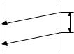
• Soft switch function description
SW-A1 No. 1 Protect from echo
Used to protect from echo in reception.
SW-A1 No. 2 Forced 4800BPS reception
When line conditions warrant that receptions take place at 4800BPS repeatedly.
It may improve the success of receptions by setting at 4800BPS.
This improves the receiving document quality and reduces handshake time due to fallback during training.
SW-A1 No. 3 Footer print
When set to "1", the date of reception, the sender machine No., and the page No. are automatically recorded at the end of reception.
SW-A1 No. 4 Length limitation of copy/send/receive
Used to set the maximum page length.
To avoid possible paper jam, the page length is normally limited to 1 meter for copy or transmit, and 1.5 meters for receive.
It is possible to set it to "No limit" to transmit a long document, such as a computer print form, etc. (In this case, the receiver must also be set to no limit.)
SW-A1 No. 5 CSI transmission
(CSI TRANSMISSION) is a switch to set whether the machine sends or does not send the signal (CSI signal) informing its own telephone No. to the remote fax machine when information is received. When "nonsending" is set, the telephone No. is not output on the remote transmitting machine if the remote transmitting machine has the function to display or print the telephone No. of receiving machine, using this CSI signal.
SW-A1 No. 6 DIS receive acknowledgment during G3 transmission
Used to make a choice of whether reception of DIS (NSF) is acknowledged after receiving two DISs (NSFs) or receiving one DIS (two NSFs). It may be useful for overseas communication to avoid an echo suppression problem, if set to 1.
SW-A1 No. 7 Non-modulated carrier for V29 transmission modem
Though transmission of a non-modulated carrier is not required for transmission by the V29 modem according to the CCITT recommendation, it may be permitted to a send non-modulated carrier before the image signal to avoid an echo suppression problem. It may be useful for overseas communication to avoid an echo suppression problem, if set to 1.
SW-A1 No. 8 EOL (End Of Line) detect timer
Used to make a choice of whether to use the 25-second or 13-second timer for detection of EOL.
This is effective to override communication failures with some facsimile models that have longer EOL detection.
SW-A2 No. 1 ~ No. 4 Modem speed
Used to set the initial modem speed. The default is 9600BPS.
It may be necessary to program it to a slower speed when frequent line fallback is encountered, in order to save the time required for fallback procedure.
SW-A2 No. 5 Sender’s information transmit
(SENDER’S INFORMATION TRANSMISSION) is a switch to set the function to print the content of HEADER PRINT described in the passcode list at the front end of receiver’s original when original is sent to the remote machine.
If this switch is set to "NO", the HEADER PRINT is not output at the receiving machine.
SW-A2 No. 6 Reserved
Set to "0".
SW-A2 No. 7 Communication error treatment in RTN sending mode (Reception)
Used to determine communication error treatment when RTN is sent by occurrence of a received image error in G3 reception. When it is set to
"1", communication error is judged as no error.
UX-510UA
FO-1470U
SW-A2 No. 8 CNG transmission
When set to "0" , this model allows CNG transmission by pressing the
Start key in the key pad dialing mode. When set to "1", CNG transmission in the key pad dialing mode cannot be performed. In either case. CNG transmission can be performed in the auto dial mode.
SW-A3 No. 1, No. 2 CED tone signal interval
For international communication, the 2100Hz CED tone may act as an echo suppression switch, causing a communication problem.
Though SW-A3 No. 1 and No. 2 are normally set to 0, this selfing is used to change the time between the CED tone signal to eliminate the communication caused by echo.
TX RX
CED
T
DIS
SW-A3 No. 3 MR Coding
MR Coding is enable.
SW-A3 No. 4 ECM mode
Used to determine ECM mode function. Refer to following table.
SW-A3 No.4 ECM MODE |
0 |
0 |
1 |
1 |
|
|
|
|
|
|
|
SW-A3 No.5 ECM MMR MODE |
0 |
1 |
0 |
1 |
|
|
|
|
|
|
|
Compression |
ECM MMR mode |
Yes |
No |
No |
No |
method |
ECM MH mode |
Yes |
Yes |
No |
No |
|
|
|
|
|
|
|
MR Mode |
Yes |
Yes |
Yes |
Yes |
(Depending on remote machine)
SW-A3 No. 5 ECM MMR mode
See SW-A3 No. 4.
SW-A3 No. 6 ~ No. 8 Reserved
Set to "0".
SW-A4 No. 1 ~ No. 5 Signal transmission level
Used to control the signal transmission level in the range of-0dB to31dB.
SW-A4 No. 6 Protocol monitor (Error print)
If set to "1", protocol is printed at communication error.
SW-A4 No. 7 Protocol monitor
Normally set to "0". If set to "1", communication can be checked, in case of trouble, without using a G3 tester or other tools.
When communication FSK data transmission or reception is made, the data is taken into the buffer. When communication is finished, the data is analysed and printed out. When data is received with the line monitor (SW-A4 No. 8) set to "1" the reception level is also printed out.
SW-A4 No. 8 Line monitor
Normally set to "0". If set to "1", the transmission speed and the reception level are displayed on the LCD. Used for line tests.
SW-A5 No. 1, No. 2 Digital line equalization setting (Reception)
Line equalization when reception is to be set according to the line characteristics.
Setting should be made according to distance between the telephone and the telephone company central switching station.
SW-A5 No. 3, No. 4 Digital line equalization setting (Transmission)
Line equalization when transmitter is to be set according to the line characteristics.
Setting should be made according to distance between the telephone and the telephone company central switching station.
2 – 13

UX-510UA
FO-1470U
SW-A5 No. 5, No. 6 Digital cable equalizer setting (Reception for Caller ID)
Line equalization when reception for CALLER ID is to be set according to the line characteristics.
Setting should be made according to distance between the telephone and the telephone company central switching station.
SW-A5 No. 7 Error criterion
Used to select error criterion for sending back RTN when receiving image data.
SW-A5 No. 8 Anti junk fax check
When using the Anti junk fax function, set to "1".
SW-A6 No. 1 Auto gain control (MODEM)
When this mode is enabled, if the reception signal level is under 31dBm, the modem itself controls the signal gain automatically.
SW-A6 No. 2 End buzzer
Setting this bit to 0 will disable the end buzzer (including the error buzzer/ on-hook buzzer).
SW-A6 No. 3 Disconnect the line when DIS is received in RX mode
Bit1= 0: When DIS signal is received during RX mode, the line is disconnected immediately.
Bit1= 1: When DIS signal is received during RX mode, the line is disconnected on the next tone.
SW-A6 No. 4 Equalizer freeze control (MODEM)
This switch is used to perform reception operation by fixing the equalizer control of modem for the line which is always in an unfavorable state and picture cannot be received.
*Usually, the control is executed according to the state of line where the equalizer setting is changed always.
SW-A6 No. 5 Equalizer freeze control 7200BPS only
Setting which specifies SW-A3 No. 6 control only in the condition of 7200BPS modem speed.
SW-A6 No. 6 CNG transmission in manual TX mode
When set to "1", fax transmit the CNG signal in case of manual transmission mode (User press the START key after waiting for the fax answering signal from handset or speaker).
SW-A6 No. 7 Reserved
Set to "0".
SW-A6 No. 8 Modem speed automatic fallback when RX level is under -40dBm
When set to "1", if fax signal level is under -40dBm during reception, machine selects the slower modem speed automatically.
It is effective when noises occur on the received document due to the long distance communications.
SW-B1 No. 1 ~ No. 4 Recall interval
Choice is made for a redial interval for speed and rapid dial calls.
Use a binary number to program this. If set to 0 accidentally, 1 will be assumed.
SW-B1 No. 5 ~ No. 8 Recall times
Choice is made as to how many redials there should be.
SW-B2 No. 1 Dialing pause (sec/pause)
Pauses can be inserted between telephone numbers of direct dial connection. Selection of 4 sec or 2 sec pause is available.
SW-B2 No. 2 Dial tone detection (before auto dial)
Used to set YES/NO of dial tone detection in auto dialing.
SW-B2 No. 3 Reserved
Set to "0".
SW-B2 No. 4 Busy tone detection (after auto dial)
Used to set busy tone detection in auto dialing.
SW-B2 No. 5, No. 6 Waiting time after dialing
This is time waiting for the opponent’s signals after dialing.
SW-B2 No. 7, No. 8 Reserved
Set to "0".
SW-B3 No. 1 ~ No. 5 Reserved
Set to "0".
SW-B3 No. 6, No. 7 Auto dial mode Delay timer of before line connect
Delay time between the dial key input and line connection under the auto dial mode.
RAPID01 |
|
CML RELAY ON |
|||||||
|
|
|
|
|
|
|
|
|
|
|
|
|
|
|
|
DIALLING |
|
|
|
|
|
|
|
|
|
|
|
||
|
|
|
|
|
|
|
|||
|
|
|
|
|
|
|
|
||
|
No.6 |
No.7 |
|
|
|
|
|
||
|
|
|
|
|
|||||
|
0 |
0 |
0sec |
|
|
|
|||
|
0 |
1 |
1.5sec |
|
|||||
|
1 |
0 |
3.0sec |
|
|||||
|
1 |
1 |
4.5sec |
|
|||||
SW-B3 No. 8 Hold key
Used to set YES/NO of holding function by the HOLD key.
SW-B4 No. 1, No. 2 Auto dial mode Delay timer of after line connect
Delay time between the line connection and dial data output under the auto dial mode.
DIAL DATA 
RAPID01 |
CML RELAY ON |
|
|
|
||||
|
|
|
|
|
|
|
|
|
|
|
|
|
|
|
|
|
|
|
|
|
|
|
|
|
|
|
|
|
|
|
|
|
|
|
|
|
|
|
|
|
|
|
||
|
|
No.1 |
No.2 |
|
|
|
||
|
|
0 |
0 |
1.7sec |
||||
|
|
0 |
1 |
3.0sec |
||||
|
|
1 |
0 |
3.6sec |
||||
|
|
1 |
1 |
4.0sec |
||||
SW-B4 No. 3 Dial mode
When using the pulse dial, set to 1. When using the tone dial, set to 0.
SW-B4 No. 4 Pulse → Tone change function by  key
key
When setting to 1, the mode is changed by pressing the  key from the pulse dial mode to the tone dial mode.
SW-B4 No. 5 Dial pulse make/break ratio (%)
When using the 33% make ratio pulse dial, set to "0".
When using the 40% make ratio pulse dial, set to "1".
SW-B4 No. 6, No. 7 Reserved
Set to "0".
SW-B4 No. 8 Recalling fixed only one time when dialing was unsuccessful without detecting busy tone signal
When dialing results in failure since the busy tone cannot be detected, recalling is fixed to one time.
Supplementary explanation
If time-out termination is made when dialing, only single recall is possible even if the setting time of recalls (SW-B1 No. 5 - No. 8) has been set to some times. This soft switch is added in order to meet FCC.
SW-B5 No. 1 ~ No. 5 DTMF signal transmission level (Low)
The transmission level of DTMF signal is adjusted. (lower frequency) 00000: 0dBm
↓
11111: -15.5dBm (-0.5dBm x 31)
SW-B5 No. 6 ~ No. 8 Reserved
Set to "0".
SW-B6 No. 1 ~ No. 5 DTMF signal transmission level (High)
The transmission level of DTMF signal is adjusted. (higher frequency)
00000: 0dBm
↓
11111: -15.5 dBm (-0.5dBm x 31)
2 – 14

SW-B6 No. 6 Dial tone detection (LCR center call)
Used to set YES/NO of dial tone detection (calling LCR center).
SW-B6 No. 7, No. 8 Reserved
Set to "0".
SW-C1 No. 1, No. 2 Reading slice (Binary)
Used to determine the set value of reading density in standard/fine mode.
The standard setting is "00" (Factory setting is "00")
SW-C1 No. 3, No. 4 Reading slice (Half tone)
Used to determine the set value of reading density in half tone mode. The standard setting is "00" (Factory setting is "00")
SW-C1 No. 5 Line density selection
Used to set the transmission mode which is automatically selected when the Resolution key is not pressed. In the copy mode, however, the fine mode is automatically selected unless the Resolution key is manually set to another mode.
SW-C1 No. 6 Reserved
Set to "0".
SW-C1 No. 7 MTF correction in half tone mode
This allows selection of MTF correction (dimness correction) in the half tone mode.
When "NO" (=1) is selected, the whole image becomes soft and mild. Clearness of characters will be reduced. Normally set to "YES" (=0).
SW-C1 No. 8 Reserved
Set to "0".
SW-D1 No. 1 ~ No. 4 Number of rings for auto receive
When the machine is set in the auto receive mode, the number of rings before answering can be selected. It may be set from one to four rings using a binary number. Since the facsimile telephone could be used as an ordinary telephone if the handset is taken off the hook, it should be programmed to the user’s choice. If the soft switch was set to 1, direct connection is made to the facsimile. If a facsimile calling beep was heard when the handset is taken off the hook, press the START key and put the handset on the hook to have the facsimile start receiving. If it was set to 0 accidentally, receive ring is set to 1.
NOTE: If the machine is set to answer after a large number of rings, it may not be able to receive faxes successfully. If you have difficulty receiving faxes, reduce the number of rings to a maximum of 6.
SW-D1 No. 5 Automatic switching manual to auto receive mode
This soft switch is used to select whether the machine should switch to the auto receive mode after 5 rings in the manual receive mode or remain in the same way as SW-D1 No. 1, No. 2, No. 3 and No. 4 "0"1"0"1"(5 rings).
SW-D1 No. 6 Reserved
Set to "0".
SW-D1 No. 7, No. 8 CI detect frequency
Detection frequency of ring signal for auto reception is set.
When set to No. 6=0, No. 7=0, frequency is set to PTT recommendation.
When set to No. 6=0, No. 7=1, frequency is set to 11.5Hz or more. When set to No. 6=1, No. 7=0, frequency is set to 13.0Hz or more. When set to No. 6=1, No. 7=1, frequency is set to 20.0Hz or more.
SW-D2 No. 1 ~ No. 3 Distinctive ringing setting (PATTERN 4 and 5 are for CANADA only)
This function allows reception of services offered by USA and Canada telephone companies in which the customer contracts with the telephone company to have up to 4 telephone numbers (USA) or 6 telephone numbers (Canada) established for one line.
Each telephone number is signalled by a different ringing pattern, and the customer can allocate each number to a specific use.
|
|
|
|
UX-510UA |
|
|
|
|
FO-1470U |
<Example of use> |
|
|
|
|
|
|
Phone Number |
Intended |
Ring Pattern |
|
|
|
Purpose |
|
|
|
|
|
|
Ring Pattern |
|
555-1234 |
Voice Calls |
Standard |
|
|
|
|
|
|
|
555-1235 |
Facsimile Calls |
Pattern 1 |
|
|
|
|
|
|
|
555-1236 |
Answering |
Pattern 2 |
|
|
|
Machine |
|
|
|
|
|
|
|
|
555-1237 |
PC Modem |
Pattern 3 |
|
|
|
|
|
<Distinctive Ringing Timing Specifications> 1) USA
DISTINCTIVE RING → 1:RING PATTERN 1 → 2:RING PATTERN 2
|
− |
|
|
|
|
|
|
|
|
↓ |
||
|
|
|
|
← |
|
|
|
|
← |
|
||
|
5:OFF SETTING |
|
4:STANDARD RING |
|
3:RING PATTERN 3 |
|||||||
2) Canada |
|
|
|
|
|
|
|
|
|
|||
|
|
|
→ |
|
|
|
|
→ |
|
|
||
|
DISTINCTIVE RING |
|
|
1:RING PATTERN 1 |
|
|
2:RING PATTERN 2 |
|||||
|
− |
|
|
|
|
|
|
|
|
↓ |
||
|
|
|
|
|
|
|
|
|
|
|
|
|
|
7:OFF SETTING |
|
|
|
|
|
|
|
|
|
3:RING PATTERN 3 |
|
|
− |
|
|
|
|
|
|
|
|
↓ |
||
6:STANDARD RING ← 5:RING PATTERN 5 ← 4:RING PATTERN 4
• Ring Pattern
STANDARD has 5 ring patterns, and DISTINCTIVE has 9 patterns. Ring patterns 1~4 for USA, and 5~9 for Canada.
However, to make the setting procedure as easy as possible for the user to understand these patterns are grouped as follows:
|
<Optional Setting> |
|
|
|
|
|
|
|
|
|
|
|
|
|
|
|
|
||
1) RING PATTERN 1 |
|
|
|
|
RING PATTERN 1 |
for USA |
|||
|
|
|
|
||||||
|
|
|
|
|
|
RING PATTERN 4 |
for USA |
||
|
|
|
|
|
|
||||
|
|
|
|
|
|
|
|
RING PATTERN 5 |
for Canada |
|
|
|
|
|
|
|
|
||
2) RING PATTERN 2 |
|
|
|
|
RING PATTERN 2 |
for USA |
|||
|
|
|
|
||||||
|
|
|
|
|
|
|
|
RING PATTERN 6 |
for Canada |
|
|
|
|
|
|
|
|
||
3) RING PATTERN 3 |
|
|
|
|
RING PATTERN 3 |
for USA |
|||
|
|
|
|
||||||
|
|
|
|
|
|
|
|
RING PATTERN 7 |
for Canada |
|
|
|
|
|
|
|
|
||
4) RING PATTERN 4 |
|
|
|
RING PATTERN 8 |
for Canada |
||||
|
|
|
|||||||
5) RING PATTERN 5 |
|
|
|
RING PATTERN 9 |
for Canada |
||||
|
|
|
|||||||
6)STANDARD RING
7)OFF SETTING
|
|
|
|
|
|
2S ring |
|
|
|
|
|
|
|
|
|
|
|
|
|
|
|
|
|||||
|
|
|
|
|
|
|
|
|
|
|
|
|
|
|
|
|
|
|
|
|
|
|
|
|
|
|
|
STANDARD |
|
|
|
|
|
|
|
|
|
|
|
|
|
|
|
|
|
|
4S ring |
||||||||
|
|
|
|
2S ring |
|
|
|
|
|
|
|
|
|
|
|
|
|
|
|
|
|
|
|
||||
|
|
|
|
|
|
|
|
|
|
|
|
|
|
|
|
|
|
|
|
|
|
|
|
||||
|
|
|
|
|
|
|
|
|
|
|
|
|
|
|
|
|
|
|
|
|
|
|
|
|
|
|
|
|
|
|
|
|
|
|
|
|
|
|
|
|
2S ring |
||||||||||||||
|
|
|
1.5S ring |
|
|
|
|
|
|
|
|
|
|
|
|
|
|
|
|
|
|
|
|||||
|
|
|
|
|
|
|
|
|
|
|
|
|
|
|
|
|
|
|
|
|
|
|
|
|
|
|
|
|
|
|
|
|
|
|
|
|
|
|
|
|
|
|
|
|
|
|
|
|
|
|
|
|
|
|
|
|
|
|
|
|
|
|
|
|
|
|
|
|
3S ring |
||||||||||||||
|
|
1S ring |
|
|
|
|
|
|
|
|
|
|
|
|
|
|
|
|
|
|
|
||||||
|
|
|
|
|
|
|
|
|
|
|
|
|
|
|
|
|
|
|
|
|
|
|
|
|
|
|
|
|
|
|
|
|
|
|
|
|
|
|
|
|
4S ring |
||||||||||||||
|
|
|
1.5S ring |
|
|
0.5S |
|||||||||||||||||||||
|
|
|
|
|
|
|
|
|
|
|
|
|
|
|
|
|
|
|
|
|
|
|
|
|
|
|
|
|
|
|
|
|
|
|
|
|
0.5S |
|
|
|
|
|
4S ring |
||||||||||||
|
|
|
|
|
|
|
|
|
|
|
|
|
|
|
|
|
|
|
|
|
|
|
|
|
|
|
|
RING |
|
0.8S |
|
|
0.8S |
|
|
|
|
|
|
|
|
|
|
|
|
|
|
|
|
||||||
PATTERN 1 |
|
|
|
|
|
|
|
|
|
|
|
|
|
|
|
|
|
|
|
|
|
|
|
|
|
|
|
for USA |
|
|
|
|
|
|
|
|
|
|
|
|
|
|
|
|
|
|
|
|
|
|
|
|
|
|
|
|
|
|
|
|
|
0.4S |
|
|
|
|
|
|
|
|
|
4S ring |
|||||||||||
|
|
|
|
|
|
|
|
|
|
|
|
|
|
|
|
|
|
|
|
|
|
|
|
|
|
|
|
RING |
|
0.3S |
1S |
0.3S |
|
|
|
|
|
|
|
|
|
|
|
|
|
|
|
|
|||||||
PATTERN 2 |
|
|
|
|
|
|
|
|
|
|
|
|
|
|
|
|
|
|
|
|
|
|
|
|
|
|
|
for USA |
|
|
|
|
|
|
|
|
|
|
|
|
|
|
|
|
|
|
|
|
|
|
|
|
|
|
|
|
|
|
0.2S 0.2S |
|
|
|
|
|
4S ring |
||||||||||||||||||
RING |
|
0.4S |
0.4S |
0.8S |
|
|
|
|
|
|
|
|
|
|
|
|
|
|
|
|
|||||||
PATTERN 3 |
|
|
|
|
|
|
|
|
|
|
|
|
|
|
|
|
|
|
|
|
|
|
|
|
|
|
|
for USA |
|
|
|
|
|
|
|
|
|
|
|
|
|
|
|
|
|
|
|
|
|
|
|
|
|
|
|
|
|
|
|
0.2S 0.2S |
|
|
|
|
|
|
4S ring |
||||||||||||||||
RING |
|
|
|
|
1S |
|
|
|
1S |
||||||||||||||||||
PATTERN 4 |
|
|
|
|
|
|
|
|
|
|
|
|
|
|
|
|
|
|
|
|
|
|
|
|
|
|
|
for USA |
|
|
|
|
|
|
|
|
|
|
|
|
|
|
|
|
|
|
|
|
|
|
|
|
|
|
|
|
|
|
|
|
|
|
|
|
1S |
|
|
|
|
|
|
|
4S ring |
||||||||||
RING |
|
|
|
|
|
|
1S |
|
1S |
||||||||||||||||||
PATTERN 5 |
|
|
|
|
|
|
|
|
|
|
|
|
|
|
|
|
|
|
|
|
|
|
|
|
|
|
|
for CANADA |
|
|
|
|
|
|
|
|
|
|
|
|
|
|
|
|
|
|
|
|
|
|
|
|
|
|
|
|
|
|
|
|
|
|
|
|
|
0.5S |
|
|
|
|
|
|
|
|
|
|
|
|
|
|
|
||
|
|
|
|
|
|
|
|
|
|
|
|
|
|
|
|
|
|
|
|
|
|||||||
RING |
|
|
|
|
|
0.5S |
|
|
|
1S |
|
|
|
|
0.5S |
||||||||||||
PATTERN 6 |
|
|
|
|
|
|
|
|
|
|
|
|
|
|
|
|
|
|
|
|
|
|
|
|
|
|
|
for CANADA |
|
|
|
|
|
|
|
|
|
|
|
|
|
|
|
|
|
|
|
|
|
|
|
|
|
|
|
|
|
|
|
|
|
|
|
0.5S |
|
|
0.5S |
||||||||||||||||
|
|
|
|
|
|
|
|
|
|
|
|
|
|
|
|
|
|
|
|
|
|||||||
RING |
|
|
|
|
|
0.5S |
|
0.5S |
|
|
|
|
1S |
||||||||||||||
PATTERN 7 |
|
|
|
|
|
|
|
|
|
|
|
|
|
|
|
|
|
|
|
|
|
|
|
|
|
|
|
for CANADA |
|
|
|
|
|
|
|
|
|
|
|
|
|
|
|
|
|
|
|
|
|
|
|
|
|
|
|
|
|
|
|
|
|
|
|
0.5S |
0.5S |
||||||||||||||||||
RING |
|
|
0.25S 0.25S 0.25S |
|
|
|
|
|
|
|
|
|
|
|
|
|
|
|
|||||||||
PATTERN 8 |
|
|
|
|
|
|
|
|
|
|
|
|
|
|
|
|
|
|
|
|
|
|
|
|
|
|
|
for CANADA |
|
|
|
|
|
|
|
|
|
|
|
|
|
|
|
|
|
|
|
|
|
|
|
|
|
|
|
|
|
|
|
|
0.2S 0.2S |
|
|
|
|
|
|
|
|
|
|
|
|
|
|
|
|
||||||
RING |
|
|
0.25S 0.25S |
|
|
|
|
|
|
|
|
|
|
|
|
|
|
|
|
||||||||
PATTERN 9 |
|
|
|
|
|
|
|
|
|
|
|
|
|
|
|
|
|
|
|
|
|
|
|
|
|
|
|
for CANADA |
|
|
|
|
|
|
|
|
|
|
|
|
|
|
|
|
|
|
|
|
|
|
|
|
|
|
|
|
|
|
|
|
0.2S |
|
|
|
|
|
|
|
|
|
|
|
|
|
|
|
|
|
|
|
|||
|
|
|
|
|
|
|
|
|
|
|
|
|
|
|
|
|
6S |
|
|
||||||||
|
|
|
|
|
|
|
|
|
|
|
|
|
|
|
|
|
|
||||||||||
|
|
|
|
|
|
|
|
|
|
|
|
|
|
|
|
|
|
|
|
|
|
|
|
|
|
|
|
2 – 15
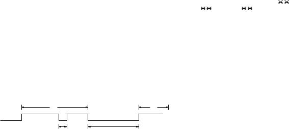
UX-510UA
FO-1470U
SW-D2 No. 4 Reserved
Set to "0".
SW-D2 No. 5 Caller ID function
Used for Caller ID function.
SW-D2 No. 6 Caller ID detect during CI off
Detection of caller ID signal is performed as follows:
0:First CI OFF only
1:All of CI OFF
SW-D2 No. 7, No. 8 Reserved
Set to "0".
SW-D3 No. 1 ~ No. 5 CI off detection timer (0-1550ms setting by 50ms step)
Set the minimum time period of CI signal interruption which affords to be judged as a CI OFF section with 50ms steps.
(Example)
A |
B |
400msec 2000msec
12
01110 (50ms ~ 14):
700ms (CI interruption>700ms:Judged as a CI OFF section) The section 1 is not judged as a CI OFF section, the CI signal A is counted as one signal.
The section 2 is judged as a CI OFF section, the CI signal B is considered as the second signal.
00111 (50ms ~ 7):
350ms (CI interruption>350ms:Judged as a CI OFF section) The section 1 is judged as a CI OFF section, and the CI signal A is counted as two signals.
The section 2 is judged as a CI OFF section, and the CI signal B is considered as the third signal.
SW-D3 No. 6 ~ No. 8 Reserved
Set to "0".
SW-E1 No. 1 ~ No. 8 Reserved
Set to "0".
SW-E2 No. 1 ~ No. 8 Reserved
Set to "0".
SW-E3 No. 1 ~ No. 8 Reserved
Set to "0".
SW-F1 No. 1, No. 2 DTMF detect time
Used to set detect time of DTMF (Dual Tone Multi Frequency) used in remote reception (5 
 ).
).
The longer the detect time is, the less the error detection is caused by noises.
SW-F1 No. 3 Protection of remote reception (5 
 ) detect
Used to set the function of remote reception (5 
 ). When set to "1", the remote reception function is disabled.
SW-F1 No. 4 Remote reception with GE telephone
(Corresponding to TEL made by GE) P. B. X.
"1": Compatible with TEL mode by GE
"0": Not compatible
•When sending (5 
 ) for remote reception with a GE manufactured telephone remote reception may not take place because of special specifications in their DTMF.
To overcome this, a soft SW is provided to change the modem setting to allow for remote reception.
•If this soft SW is set to "1", other telephone sets may be adversely affected.
SW-F1 No. 5 ~ No. 8 Remote operation code figure by external TEL (0 ~ 9)
Remote operation codes can be changed from 0 through 9. If set to
greater than 9, it defaults to 9. The "5 |
" is not changed. |
||
Ex-7 |
(Default: 5 |
) |
|
SW-F2 No. 1 CNG detection in STAND-BY mode
When setting to "1", the CNG signal detection function during standby stops.
SW-F2 No. 2, No. 3 Number of CNG detect (AM mode)
Used for detection of CNG in 1 to 4 pulses.
SW-F2 No. 4, No. 5 Number of CNG detect (STAND-BY mode)
Used for detection of CNG in 1 to 4 pulses.
SW-F2 No. 6 ~ No. 8 Reserved
Set to "0".
SW-G1 No. 1 ~ No. 4 Quiet detect time
When an answering machine is connected, if a no sound state is detected for a certain period of time, the machine judges it as a transmission from a facsimile machine and automatically switches to the FAX mode.
SW-G1 No. 5 ~ No. 8 Quiet detect start timing
Inserts a pause before commencing quiet detection.
SW-G2 No. 1 ~ No. 8 Reserved
Set to "0".
SW-G3 No. 1, No. 2 OGM detect timer
This is used to change the OGM detection time for answering machine hook up detection.
SW-G3 No. 3, No. 4 Reserved
Set to "0".
SW-G3 No. 5, No. 6 Selection time of quiet detection
The switch which sets the time from the start of detection function to the end of the function.
SW-G3 No. 7 Choice after quiet detect
"0": The reception begins when no sound is detected in A.M. mode.
"1": The DIS signal is transmitted only once when no sound is detected in A.M. mode.
SW-G3 No. 8 Reserved
Set to "0".
SW-H1 No. 1, No. 2 Busy tone detection ON/OFF time (Lower duration)
The initial value of detection is set according to electric condition.
The set value is changed according to the local switch board. (Erroneous detection of sound is reduced.)
Normally the upper limit is set to 900msec, and the lower limit to 200msec.
If erroneous detection is caused by sound, etc., adjust the detection range.
The lower limit can be set in the range of 350msec to 150msec.
2 – 16
SW-H1 No. 3, No. 4 Busy tone detection ON/OFF time (Upper duration)
Similarly to SW-H1 No. 1, the set value can be varied.
The upper limit can be set in the range of 650msec to 2700msec.
SW-H1 |
SW-H1 |
SW-H1 |
SW-H1 |
Detection range |
|
No. 1 |
No. 2 |
No. 3 |
No. 4 |
||
|
|||||
|
|
|
|
|
|
0 |
0 |
0 |
0 |
150msec ~ 650msec |
|
|
|
|
|
|
|
0 |
0 |
0 |
1 |
150msec ~ 900msec |
|
|
|
|
|
|
|
0 |
0 |
1 |
0 |
150msec ~ 1500msec |
|
|
|
|
|
|
|
0 |
0 |
1 |
1 |
150msec ~ 2700msec |
|
|
|
|
|
|
|
0 |
1 |
0 |
0 |
200msec ~ 650msec |
|
|
|
|
|
|
|
0 |
1 |
0 |
1 |
200msec ~ 900msec |
|
0 |
1 |
1 |
0 |
200msec ~ 1500msec |
|
|
|
|
|
|
|
0 |
1 |
1 |
1 |
200msec ~ 2700msec |
|
|
|
|
|
|
|
1 |
0 |
0 |
0 |
250msec ~ 650msec |
|
|
|
|
|
|
|
1 |
0 |
0 |
1 |
250msec ~ 900msec |
|
|
|
|
|
|
|
1 |
0 |
1 |
0 |
250msec ~ 1500msec |
|
|
|
|
|
|
|
1 |
0 |
1 |
1 |
250msec ~ 2700msec |
|
|
|
|
|
|
|
1 |
1 |
0 |
0 |
350msec ~ 650msec |
|
|
|
|
|
|
|
1 |
1 |
0 |
1 |
350msec ~ 900msec |
|
|
|
|
|
|
|
1 |
1 |
1 |
0 |
350msec ~ 1500msec |
|
|
|
|
|
|
|
1 |
1 |
1 |
1 |
350msec ~ 2700msec |
SW-H1 No. 5 Reserved
Set to "0".
SW-H1 No. 6 Busy tone detect continuation sound detect (during ICM: for internal A.M.)
Used to select detection of the continuous sound of certain frequency.
SW-H1 No. 7 Reserved
Set to "0".
SW-H1 No. 8 Busy tone detect intermittent sound detect (during ICM: for internal A.M.)
Used to select detection of the intermittent sound of certain frequency.
SW-H2 No. 1, No. 2 Busy tone detection pulse number
Used to set detection of Busy tone intermittent sounds.
SW-H2 No. 3 Fax switching when A.M. full
If the answering machine’s memory (tape) is full and there is no response, the machine automatically switches to Fax reception.
SW-H2 No. 4 ~ No. 7 Reserved
Set to "0".
SW-H2 No. 8 Busy tone continuous sound detect time
Set detecting time busy tone continuous sound for 5 or 10 seconds.
SW-I1 No. 1 ~ No. 8 Reserved
Set to "0".
SW-I2 No. 1 ~ No. 8 Reserved
Set to "0".
SW-I3 No. 1 ~ No. 8 Reserved
Set to "0".
SW-I4 No. 1 ~ No. 8 Reserved
Set to "0".
SW-I5 No. 1 ~ No. 8 Reserved
Set to "0".
SW-I6 No. 1 ~ No. 8 Reserved
Set to "0".
UX-510UA
FO-1470U
SW-I7 No. 1 ~ No. 8 Reserved
Set to "0".
SW-J1 No. 1 Activity report print
This soft switch is used to select: whether or not to print out the activity report when the memory is full. An activity report can be printed when the following key entry command is made.
"FUNCTION", "2", "#", "START"
After producing the activity report, all the data in the memory will be cleared.
When the switch function is set to "0" (no), the data in the memory will be deleted from the oldest as it reaches the maximum memory capacity.
SW-J1 No. 2 Total communication hours and pages print
Used to make a choice of whether the total communication time and pages are recorded in the activity report.
SW-J1 No. 3 Sender’s phone number setting
Used to make a choice of whether the registered sender’s phone number can be changed or not. If the switch is set to "1", new registration of the sender’s phone number is disabled to prevent accidental wrong input.
SW-J1 No. 4, No. 5 Reserved
Set to "0".
SW-J1 No. 6 Summer time setting
This is used to set YES/NO of automatic clock adjustment for European
Summer time.
SW-J1 No. 7, No. 8 Ringer volume
Used to adjust ringing volume.
SW-J2 No. 1, No. 2 Speaker volume (3 stages)
Used to adjust sound volume from a speaker.
SW-J2 No. 3 Polling key
If this switch is set to 1, the last of Rapid key works as polling key.
SW-J2 No. 4, No. 5 Handset receiver volume
Used to adjust sound volume from a handset receiver volume.
SW-J2 No. 6 ~ No. 8 Reserved
Set to "0".
SW-J3 No. 1 Automatic cover sheet
The machine automatically generates a cover sheet and sends it as the last page of each transmission.
SW-J3 No. 2 ~ No. 4 Communication result printout (Transaction report)
Every communication, the result can be output. As usual, it is set to print the timer sending communication error alone. If No. 2: 0 No. 3: 1 No. 4: 0 are set, printing is always on (printed even if it is normally ended).
000: Error, timer and memory sending/receiving
001: Sending
010: Continuous printing
011: Not printed
100: Communication error
SW-J3 No. 5 ~ No. 8 Reserved
Set to "0".
SW-K1 No. 1 Entering DIAG mode by pressing SPEED key
A bit which is used in the production process only.When the SPEED key is pressed, the switch is changed from the stand-by state to the DIAG mode.
SW-K1 No. 2 ~ No. 8 Reserved
Set to "0".
SW-L1 No. 1 ~ No. 4 Reserved
Set to "0".
2 – 17
UX-510UA
FO-1470U
SW-L1 No. 5 Cut off mode (COPY mode)
Whether the excessive part is printed on the next recording paper or discarded is selected to copy a document which is longer than the recording paper.
SW-L1 No. 6 A4 Paper enable
The use of recording paper of A4 is enabled.
SW-L1 No. 7 LEGAL and LETTER paper enable
The use of recording paper of LEGAL and LETTER is enabled.
SW-L1 No. 8 2 IN 1 mode
A function to print transmitted data of two pages on one sheet.
SW-L2 No. 1, No. 2 Paper set size
At present size of the recording paper.
SW-L2 No. 3 Automatic reduce of receive
If set to 1, it is reduced automatically when receiving.
SW-L2 No. 4 Print contrast
0:Normal
1:Light
SW-L2 No. 5 Reception reduction ratio in case of memory full
This model is designed so that the print is started according to the setting of SW-L2 No.3 when reception of one page is completed. However, if the memory is filled with data before completion of reception of one page, the print is started with the reduction ratio which is set with this switch.
SW-L2 No. 6 ~ No. 8 Reserved
Set to "0".
SW-M1 No. 1 ~ No. 8 Reserved
Set to "0".
SW-M2 No. 1 ~ No. 8 Reserved
Set to "0".
SW-N1 No. 1 ~ No. 6 LCR short time
First time setting transmitting to the Open LCR center.
SW-N1 No. 7, No. 8 Reserved
Set to "0".
SW-N2 No. 1 ~ No. 6 LCR long time
Second time setting transmitting to the Open LCR center.
SW-N2 No. 7, No. 8 Reserved
Set to "0".
SW-N3 No. 1 LCR Time Select
Used to select LCR short time or LCR long time.
0:LCR short time is selected. 1:LCR long time is selected.
SW-N3 No. 2 Temporary release of caller ID withhold
Used to do temporary release of caller ID withhold.
0:Normal dialing.
1:Release of caller ID withhold before dialing.
SW-N3 No. 3 Connect Japanese center
Used to connect Japanese open LCR center.
0:Connect USA open LCR center. 1:Connect Japanese open LCR center.
SW-N3 No. 4 Open LCR debug mode
Used to debug open LCR function.
0:Normal mode. 1:debug mode.
SW-N3 No. 5, No. 6 Digital egualization setting (Recept for LCR V23 mode)
Line egualization when Open LCR table download is to be set according to the line characteristics.
Setting should be made according to distance between the telephone and the telephone company central switching station.
SW-N3 No. 7, No. 8 Reserved
Set to "0".
2 – 18
 Loading...