


R-241CWAA
R-241CWAC
R-241CWAP
SERVICE MANUAL
S7908R241CPA/
MICROWAVE OVEN
MODELS R-241CWAA (Argentina)
R-241CWAC (Chile)
R-241CWAP (Peru)
In interests of user-safety the oven should be restored to its original condition and only parts identical to those specified should be used.
TABLE OF CONTENTS |
|
CAUTION, MICROWAVE RADIATION ............................................................................................................... |
1 |
WARNING ............................................................................................................................................................ |
1 |
PRODUCT SPECIFICATIONS ........................................................................................................................... |
2 |
GENERAL INFORMATION .................................................................................................................................. |
2 |
APPEARANCE VIEW ......................................................................................................................................... |
3 |
OPERATION SEQUENCE .................................................................................................................................. |
4 |
FUNCTION OF IMPORTANT COMPONENTS .................................................................................................. |
5 |
SERVICING ......................................................................................................................................................... |
6 |
TEST PROCEDURE ........................................................................................................................................... |
8 |
TOUCH CONTROL PANEL ............................................................................................................................... |
14 |
COMPONENT REPLACEMENT AND ADJUSTMENT PROCEDURE ............................................................. |
18 |
MICROWAVE MEASUREMENT ...................................................................................................................... |
24 |
WIRING DIAGRAM ........................................................................................................................................... |
25 |
PICTORIAL DIAGRAM ..................................................................................................................................... |
26 |
CONTROL PANEL CIRCUIT ............................................................................................................................. |
27 |
PRINTED WIRING BOARD ............................................................................................................................... |
28 |
PARTS LIST ..................................................................................................................................................... |
29 |
SHARP CORPORATION

R-241CWAA R-241CWAC R-241CWAP
SERVICE MANUAL
MICROWAVE OVEN
R-241CWAA (Argentina)
R-241CWAC (Chile)
R-241CWAP (Peru)
GENERAL IMPORTANT INFORMATION
This Manual has been prepared to provide Sharp Corp. Service engineers with Operation and Service Information.
It is recommended that service engineers carefully study the entire text of this manual, so they will be qualified to render satisfactory customer service.
CAUTION
MICROWAVE RADIATION
DO NOT BECOME EXPOSED TO RADIATION FROM THE MICROWAVE GENERATOR OR OTHER PARTS CONDUCTING MICROWAVE ENERGY.
Service engineers should not be exposed to the microwave energy which may radiate from the magnetron or other microwave generating devices if it is improperly used or connected. All input and output microwave connections, waveguides, flanges and gaskets must be secured. Never operate the device without a microwave energy absorbing load attached. Never look into an open waveguide or antenna while the device is energized.
WARNING
Never operate the oven until the following points are ensured.
(A)The door is tightly closed.
(B)The door brackets and hinges are not defective.
(C)The door packing is not damaged.
(D)The door is not deformed or warped.
(E)There is not any other visible damage with the oven.
Servicing and repair work must be carried out only by trained service engineers.
All the parts marked "*" on parts list are used at voltages more than 250V.
Removal of the outer wrap gives access to potentials above 250V.
All the parts marked " " on parts list may cause undue microwave exposure, by themselves, or when they are damaged, loosened or removed.
SHARP CORPORATION
OSAKA, JAPAN
R-241CWAA
R-241CWAC
R-241CWAP
PRODUCT SPECIFICATIONS
APPEARANCE VIEW
OPERATING SEQUENCE
FUNCTION OF IMPORTANT
COMPONENTS
SERVICING AND TROUBLESHOOTING CHART
TEST PROCEDURE
TOUCH CONTROL PANEL
ASSEMBLY
COMPONENT REPLACEMENT AND ADJUSTMENT PROCEDURE
MICROWAVE MEASUREMENT
WIRING DIAGRAM
PARTS LIST
1

R-241CWAA
R-241CWAC
R-241CWAP
|
PRODUCT SPECIFICATIONS |
|
|
|
|
ITEM |
|
DESCRIPTION |
Power Requirements |
R-241CWAA, R-241CWAC : |
220 Volts / 50 Hertz |
|
Single phase, 3 wire earthed |
|
|
|
|
|
|
|
|
R-241CWAP (Peru) : |
220 Volts / 60 Hertz |
|
Single phase, 2 wire |
|
|
|
|
|
|
|
Power Consumption |
1.2 kW |
|
|
|
|
Power Output |
800 watts nominal of RF microwave energy (IEC 705) |
|
|
Operating frequency 2450 MHz |
|
|
|
|
Case Dimensions |
Width 460 mm |
|
|
Height 290 mm including foot |
|
|
Depth 372 mm |
|
|
|
|
Cooking Cavity Dimensions |
Width 314 mm |
|
|
Height 199 mm |
|
|
Depth 321 mm |
|
|
|
|
Turntable diameter |
295 mm |
|
|
|
|
Control Complement |
Touch Control System |
|
|
Timer (0 - 99 minutes 99 seconds) |
|
|
Microwave Power for Variable Cooking |
|
|
Repetition Rate; |
|
|
HIGH ....................................... |
Full power throughout the cooking time |
|
MEDIUM HIGH ........................................ |
approx. 70% of FULL Power |
|
MEDIUM .................................................. |
approx. 50% of FULL Power |
|
MEDIUM LOW ......................................... |
approx. 30% of FULL Power |
|
LOW......................................................... |
approx. 10% of FULL Power |
|
EASY DEFROST pad |
|
|
INSTANT ACTION pads |
|
|
Number pads |
|
|
POWER LEVEL pad |
|
|
TIMER/CLOCK pad |
|
|
STOP/CLEAR pad |
|
|
INSTANT COOK/START pad |
|
Set Weight (Approx.) |
14 kg |
|
|
|
|
GENERAL INFORMATION
WARNING
THIS APPLIANCE MUST BE EARTHED
IMPORTANT
THE WIRES IN THIS MAINS LEAD ARE COLOURED IN ACCORDANCE WITH THE FOLLOWING CODE:
GREEN-AND-YELLOW (for R-241CWAA & R-241CWAC): EARTH
BLUE : |
NEUTRAL |
BROWN : |
LIVE |
2
R-241CWAA
R-241CWAC
R-241CWAP
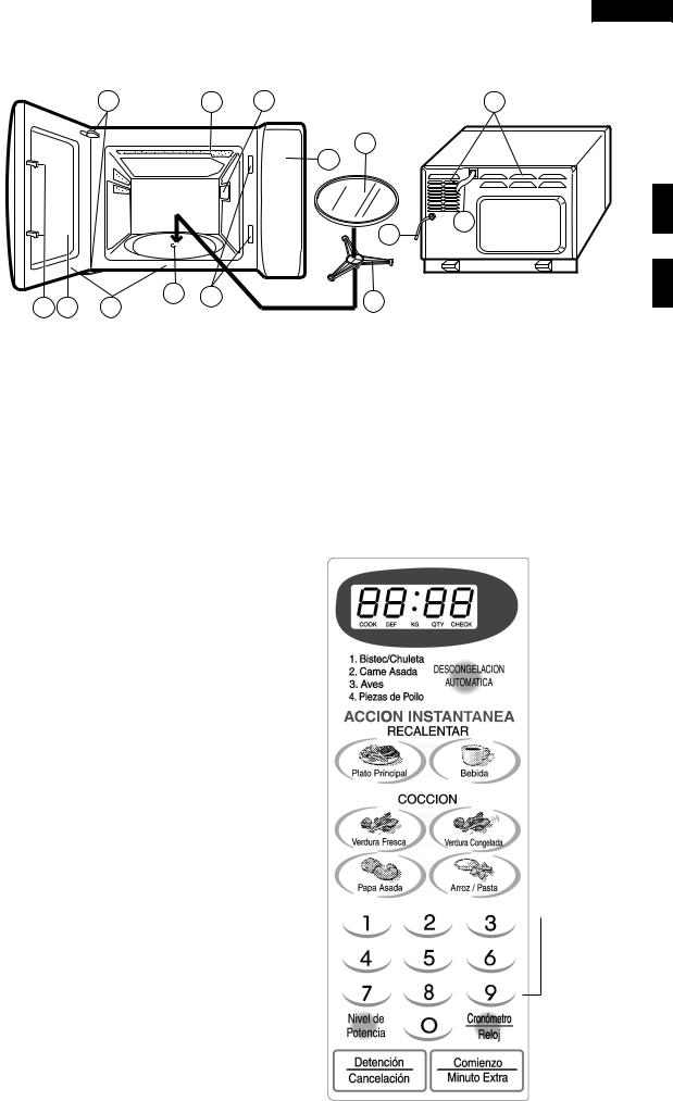
APPEARANCE VIEW
3 |
2 |
9 |
1 |
OVEN
11
8
|
|
|
|
10 |
|
|
|
|
13 |
4 |
5 |
7 |
4 |
12 |
6 |
|
|||
1. Ventilation openings |
|
8. Control panel |
||
2. Oven lamp |
|
|
9. Waveguide cover |
|
3. Door hinges |
|
|
10. Power supply cord |
|
4. Door safety latches |
|
11. Turntable |
||
5. See through door |
|
12. Roller stay |
||
6. Door seals sealing surfaces |
|
13. Earth wire [R-241CWAP] |
||
7. Coupling |
|
|
|
|
|
TOUCH CONTROL PANEL |
|
|
|
|
|
|
1. |
DIGITAL READOUT |
|
|
|
|
|
1 |
|
|
|
|
|
|||
|
|
|
|
|
2 |
||
2. |
INDICATOR |
|
|
|
|
|
|
|
|
|
|
||||
3. |
EASY DEFROST PAD |
|
|
|
|
|
|
|
Press to select the Easy Defrost menu. |
|
|
|
|
|
3 |
4. |
INSTANT ACTION PADS |
|
|
|
|
||
|
|
|
|||||
|
Press to cook or reheat 6 popular menus. |
|
|
|
|
|
|
5. |
NUMBER PADS |
|
|
|
|
|
|
|
Press to enter cooking time, clock time, weight of |
|
|
|
|
|
|
|
food. |
|
|
|
|
|
|
|
|
|
|
|
|
|
|
6. |
POWER LEVEL PAD |
|
|
|
|
|
|
|
Press to select microwave power setting. |
|
|
|
|
|
|
|
If not pressed, HIGH is automatically selected. |
|
|
|
|
|
4 |
|
Press to alter the cooking result for automatic |
|
|
|
|||
|
|
|
|
|
|
||
|
operations. |
|
|
|
|
|
|
7. |
TIMER/CLOCK PAD |
|
|
|
|
|
|
|
Press to set clock, timer, child lock or demonstra- |
|
|
|
|
|
|
|
|
|
|
|
|
|
|
|
tion mode. |
|
|
|
|
|
|
8. |
STOP/CLEAR PAD |
|
|
|
|
|
|
|
Press to clear during programming. |
|
|
|
|
|
|
|
Press once to stop operation of oven during cook- |
|
|
|
|
|
5 |
|
ing; press twice to cancel cooking programme. |
|
|
||||
|
|
||||||
9.INSTANT COOK/START PAD
Press once to cook for 1 minute at 100% or increase by 1 minute multiples each time this pad is
pressed during cooking. |
6 |
|
|
|
|
|
7 |
|
|
|
|
|
|||
|
|
||||||
Press to start oven after setting programmes. |
8 |
|
|
|
|
|
9 |
|
|
|
|
|
|
||
|
|
|
|
|
|
||
|
|
3

R-241CWAA
R-241CWAC
R-241CWAP
OPERATION SEQUENCE
OFF CONDITION
Closing the door activates all door interlock switches (1st. latch switch, 2nd. interlock relay control switch).
IMPORTANT
When the oven door is closed, the monitor switch contacts (COM-NC) must be open.
When the microwave oven is plugged in a wall outlet, rated voltage is supplied to the control unit.
Figure O-1 on page 25
1.The display flashes "88:88".
2.To set any programmes or set the clock, you must first touch the stop/ clear pad.
3." : " appears in the display.
NOTE: When the oven door is opened, the oven lamp comes on at this time.
MICROWAVE COOKING CONDITION
HIGH COOKING
Enter a desired cooking time with the touching the number keys and start the oven with touching the start key.
Function sequence
Figure O-2 on page 25
CONNECTED COMPONENTS |
RELAY |
Oven lamp, Fan motor, Turntable motor |
RY1 |
|
|
Power transformer |
RY2 |
1.Rated voltage is supplied to the primary winding of the power transformer. The voltage is converted to about 3.3 volts A.C. output on the filament winding and high voltage of approximately 2000 volts A.C. on the secondary winding.
2.The filament winding voltage (3.3 volts) heats the magnetron filament and the high voltage (2000 volts) is sent to the voltage doubling circuit, where it is doubled to negative voltage of approximately 4000 volts D.C..
3.The 2450 MHz microwave energy produced in the magnetron generates a wave length of 12.24 cm. This energy is channelled through the waveguide (transport channel) into the oven cavity, where the food is placed to be cooked.
4.When the cooking time is up, a signal tone is heard and the relays RY1+RY2 go back to their home position. The circuits to the oven lamp, power transformer, fan motor and turntable motor are cut off.
5.When the door is opened during a cook cycle, the switches come to the following condition.
|
|
CONDITION |
|
|
|
DURING |
DOOR OPEN |
SWITCH |
CONTACT |
COOKING |
(NO COOKING) |
|
|
|
|
1st. latch switches |
COM-NO |
Closed |
Open |
|
|
|
|
2nd. interlock relay |
COM-NO |
Closed |
Open |
control switch |
|
|
|
Monitor switch |
COM-NC |
Open |
Closed |
The circuits to the power transformer, fan motor and turntable motor are cut off when the 1st. latch switch and 2nd. interlock relay control switch are made open.
The oven lamp remains on even if the oven door is opened after the cooking cycle has been interrupted, because the relay RY1 stays closed. Shown in the display is the remaining time.
6.MONITOR SWITCH CIRCUIT
The monitor switch is mechanically controlled by oven door, and monitors the operation of the 1st. latch switch and the 2nd. interlock relay.
6-1 When the oven door is opened during or after the cycle of a cooking program, the 1st. latch switch and 2nd. interlock relay control switch must open their contacts first. After that the contacts (COM-NC) of the monitor switch can be closed.
6-2. When the oven door is closed, the contacts (COM-NC) of the monitor switch must be opened. After that the contacts of the 1st. latch switch and 2nd. interlock relay control switch are closed.
6-3. When the oven door is opened and the contacts of the 1st latch switch and 2nd. interlock relay remain closed. The fuse M8A will blow, because the monitor switch is closed and a short circuit is caused.
MEDIUM HIGH, MEDIUM, MEDIUM LOW, LOW COOKING
When the microwave oven is preset for variable cooking power, rated voltage is supplied to the power transformer intermittently within a 32-second time base through the relay contact which is coupled with the current-limiting relay. The following levels of microwave power are given.
SETTING; |
|
32 sec. ON |
|
|
|
||
HIGH |
|
|
|
|
|
|
|
|
|
|
|
|
|
|
|
|
|
|
|
|
|
|
|
|
|
24 sec. ON |
8 sec. OFF |
||||
|
MEDIUM HIGH |
|
|
|
|
|
Approx. 70% |
|
|
18 sec. ON |
14 sec. OFF |
||||
|
MEDIUM |
|
|
|
|
|
Approx. 50% |
|
|
12 sec. ON |
20 sec. OFF |
||||
|
MEDIUM LOW |
|
|
|
|
|
Approx. 30% |
|
|
6 sec. ON |
26 sec. OFF |
||||
|
LOW |
|
|
|
|
|
Approx. 10% |
NOTE: The ON/OFF time ratio does not exactly correspond to the percentage of microwave power, because approx. 2 seconds are needed for heating up the magnetron filament.
4
R-241CWAA
R-241CWAC
R-241CWAP
FUNCTION OF IMPORTANT COMPONENTS
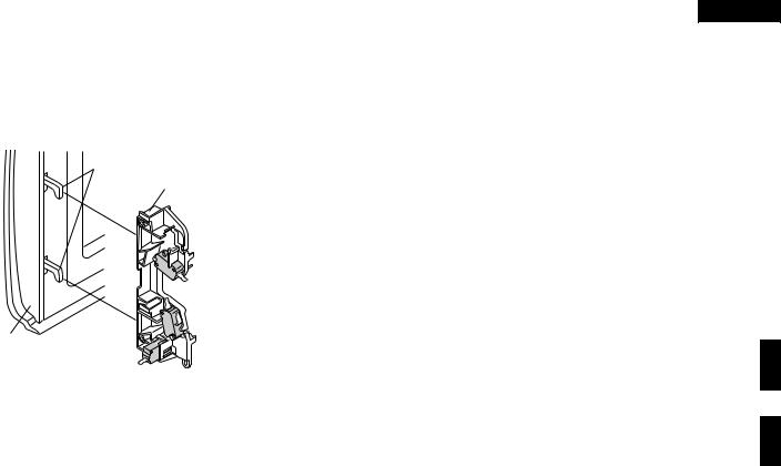
DOOR OPEN MECHANISM
The door is opened by pulling the door, refer to the Figure D- 1.
Latch Hook
 2nd. Interlock
Relay Control
Switch
|
|
Monitor |
Door |
1st. Latch |
Switch |
Switch |
|
|
|
|
Figure D-1. Door Open Mechanism
1ST. LATCH SWITCH AND 2ND. INTERLOCK RELAY CONTROL SWITCH
1.When the oven door is closed, the contacts (COM-NO) must be closed.
2.When the oven door is opened, the contacts (COM-NO) must be opened.
MONITOR SWITCH
1.When the oven door is closed, the contacts (COM-NC) must be opened.
2.When the oven door is opened, the contacts (COM-NC) must be closed.
3.If the oven door is opened and the contacts (COM-NO) of the 1st latch switch and 2nd. interlock relay fail to open, the fuse blows simultaneously with closing the contacts (COM-NC) of the monitor switch.
CAUTION: BEFORE REPLACING A FUSE TEST THE 1ST LATCH SWITCH, 2ND. INTERLOCK RELAY(RY2), 2ND. INTERLOCK RELAY CONTROL SWITCH, MONITOR SWITCH AND MONITOR RESISTOR FOR PROPER OPERATION. (REFER TO CHAPTER "TEST PROCEDURE".)
HIGH VOLTAGE FUSE
The high voltage fuse blows when the high voltage rectifier or the magnetron is shorted.
THERMAL CUT-OUT 125˚C (OVEN)
The thermal cut-out located on the top of the oven cavity is designed to prevent damage to the oven if the foods in the oven catch fire due to over heating produced by improper setting of cook time or failure of control unit. Under normal operation, the thermal cut-out remains closed. However, when abnormally high temperatures are reached within the oven cavity, the thermal cut-out will open at 125˚C, causing the oven to shut down. The defective thermal cut-out must be replaced with a new one.
THERMAL CUT-OUT 95˚C (MAGNETRON )
The thermal cut-out located on the top of the oven cavity is designed to prevent damage to the magnetron if an over heated condition develops in the tube due to cooling fan failure, obstructed air guide, dirty or blocked air intake, etc. Under normal operation, the thermal cut-out remains closed. However, when abnormally high temperatures are reached to the thermal cut-out , it will open at 95˚C, causing the oven to shut down. When the magnetron has cooled to 75˚C, the thermal cut-out closes and cook cycle will resume.
TURNTABLE MOTOR
The turntable motor drives the roller stay to rotate the turntable.
FAN MOTOR
The fan motor drives a blade which draws external cool air. This cool air is directed through the air vanes surrounding the magnetron and cools the magnetron. This air is channelled through the oven cavity to remove steam and vapours given off from the heating foods. It is then exhausted through the exhausting air vents at the oven cavity.
MONITOR RESISTOR 0.8Ω 20W
The monitor resistor prevents the fuse bursting when the fuse blows due to the operation of the monitor switch.
FUSE
1.The fuse blows when the contacts (COM-NO) of the 1st latch switch and 2nd. interlock relay remain closed with the oven door open and when the monitor switch closes.
2.If the wire harness or electrical components are shortcircuited, the fuse M8A blows to prevent an electric shock of fire hazard.
5

R-241CWAA
R-241CWAC
R-241CWAP
SERVICING
WARNING TO SERVICE PERSONNEL
Microwave ovens contain circuitry capable of producing very high voltage and current, contact with any part of the high voltage circuit will result in electrocution. High voltage capacitor, Power transformer, Magnetron, High voltage rectifier assembly, High voltage fuse, High voltage harness.
REMEMBER TO CHECK 3D
1)Disconnect the supply.
2)Door opened, and wedged open.
3)Discharge high voltage capacitor.
WARNING: AGAINST THE CHARGE OF THE HIGH-VOLTAGE CAPACITOR
The high-voltage capacitor remains charged about 60 seconds after the oven has been switched off. Wait for 60 seconds and then short-circuit the connection of the high-voltage capacitor (that is, of the connecting lead of the high-voltage rectifier) against the chassis with the use of an insulated screwdriver.
Sharp recommend that wherever possible fault-finding is carried out with the supply disconnected. It may in, some cases, be necessary to connect the supply after the outer case has been removed, in this event carry out 3D checks and then disconnect the leads to the primary of the power transformer. Ensure that these leads remain isolated from other components and the oven chassis. (Use insulation tape if necessary.) When the testing is completed carry out 3D checks and reconnect the leads to the primary of the power transformer.
REMEMBER TO CHECK 4R
1)Reconnect all leads removed from components during testing.
2)Replace the outer case (cabinet).
3)Reconnect the supply.
4)Run the oven. Check all functions.
Microwave ovens should not be run empty. To test for the presence of microwave energy within a cavity, place a cup of cold water on the oven turntable, close the door and set the power level to HIGH. And set the microwave timer for two (2) minutes. When the two minutes has elapsed (timer at zero) carefully check that the water is now hot. If the water remains cold carry out 3D checks and re-examine the connections to the component being tested.
When all service work is completed and the oven is fully assembled, the microwave power output should be checked and microwave leakage test should be carried out.
TROUBLESHOOTING GUIDE
When troubleshooting the microwave oven, it is helpful to |
IMPORTANT: If the oven becomes inoperative because of |
follow the Sequence of Operation in performing the checks. |
a blown fuse M8A in the 1st. latch switch - |
Many of the possible causes of trouble will require that a |
2nd. interlock relay - monitor switch - moni- |
specific test be performed. These tests are given a proce- |
tor resistor circuit, check the 1st. latch switch, |
dure letter which will be found in the "Test Procedure"section. |
2nd. interlock relay, 2nd. interlock relay con- |
|
trol switch, monitor switch and monitor |
|
resistor before replacing the fuse M8A. |
6

TEST PROCEDURE
POSSIBLE CAUSE
AND
DEFECTIVE PARTS
CONDITION PROBLEM
|
Home fuse blows when power |
|
supply cord is plugged into |
|
wall outlet. |
|
FUSE M8A blows when power |
|
supply cord is plugged into |
|
wall outlet. |
OFF |
"88:88" does not appear in dis- |
CONDITION |
play but power supply cord is |
|
|
|
plugged into wall outlet. |
|
Display does not operate prop- |
|
erly when stop/clear pad is |
|
touched. |
|
Oven lamp does not light at |
|
door opened. (Display ap- |
|
pears.) |
|
Oven does not start when the |
|
start pad is touched. (Display |
|
appears) |
|
Oven lamp does not light (Dis- |
|
play appears.) |
|
Fan motor does not operate. |
|
(Display appears.) |
|
Turntable motor does not op- |
|
erate. (Display appears.) |
|
Oven or any electrical parts |
|
does not stop when cooking |
|
time is 0 or stop/clear pad is |
ON |
touched. |
CONDITION |
|
|
Oven seems to be operating |
|
but little or no heat is produced |
|
in oven load. (Microwave |
|
power level is set at HIGH) |
|
Oven does not seems to be |
|
operating properly when ME- |
|
DIUM HIGH, MEDIUM, ME- |
|
DIUM LOW or LOW is set. |
|
(Oven operates properly at |
|
HIGH and then the stop/clear |
|
pad is touched the oven |
|
stops.) |
|
Oven goes into cook cycle but |
|
shuts down before end of cook- |
|
ing cycle. |
R-241CWAA
R-241CWAC
R-241CWAP
CK = Check / RE = Replace
A B |
C CK D E |
E E F G G H H |
I |
K M N RE CK CK RE CK CK CK CK CK L J |
|
|||||||||||||||||||||||
MAGNETRON |
POWER TRANSFORMER |
H.V. RECTIFIER ASSEMBLY |
HIGH VOLTAGE WIRE |
HIGH VOLTAGE CAPACITOR |
1ST. LATCH SWITCH |
2ND. INTERLOCK RELAY CONTROL SWITCH |
MONITOR SWITCH |
MONITOR RESISTOR |
THERMAL CUT-OUT 125˚C (OVEN) |
THERMAL CUT-OUT 95˚C (MG) |
FAN MOTOR |
TURNTABLE MOTOR |
FUSE M8A |
TOUCH CONTROL PANEL |
RELAY (RY-1, RY-2) |
FOIL PATERN ON P.W.B. |
POWER SUPPLY CORD |
SHORTED WIRE HARNESS |
OPENED WIRE HARNESS |
OVEN LAMP OR SOCKET |
WALL OUTLET |
MISADJUSTMENT SWITCH |
HOME FUSE OR BREAKER |
BLOCKED COOLING FAN |
BLOCKED VENTILATION |
KEY UNIT |
H.V. FUSE |
|
|
|
|
|
|
|
|
|
|
|
|
|
|
|
|
|
|
|
|
|
|
|
|
|
|
|
|
|
|
|
|
|
|
|
|
|
|
|
|
|
|
|
|
|
|
|
|
|
|
|
|
|
|
|
|
|
|
|
7

R-241CWAA
R-241CWAC
R-241CWAP
TEST PROCEDURES
PROCEDURE
COMPONENT TEST
LETTER
A MAGNETRON TEST
NEVER TOUCH ANY PART IN THE CIRCUIT WITH YOUR HAND OR AN INSULATED TOOL WHILE THE OVEN IS IN OPERATION.
CARRY OUT 3D CHECKS.
Isolate the magnetron from the high voltage circuit by removing all leads connected to the filament terminal.
To test for an open circuit filament use an ohmmeter to make a continuity test between the magnetron filament terminals, the meter should show a reading of less than 1 ohm.
To test for a short circuit filament to anode condition, connect ohmmeter between one of the filament terminals and the case of the magnetron (ground). This test should be indicated an infinite resistance. If a low or zero resistance reading is obtained then the magnetron should be replaced.
MICROWAVE OUTPUT POWER (1 litre water load)
The following test procedure should be carried out with the microwave oven in a fully assembled condition (outer case fitted). Microwave output power from the magnetron can be measured by way of IEC 705, i.e. it can be measured by using water load how much it can be absorbed by the water load. To measure the microwave output power in the microwave oven, the relation of calorie and watt is used. When P(W) heating works for t(second), approximately P x t/4.187 calorie is generated. On the other hand, if the temperature of the water with V(ml) rises T (˚C) during this microwave heating period, the calorie of the water is V x T.
The formula is as follows; |
|
|
|
|
P x t / 4.187 = V x T |
P (W) = 4.187 x V x |
T / t |
|
|
Our condition for water load is as follows: |
|
|
||
Room temperature.............. |
around 20˚C |
Power supply Voltage......... |
Rated voltage |
|
Water load |
.........1000 g |
Initial temperature........... |
10±2°C Heating time......... |
52 sec. |
P = 80 x |
T |
|
|
|
|
|
|
|
|
Measuring condition:
1.Container
The water container must be a cylindrical borosilicate glass vessel having a maximum material thickness of 3 mm and an outside diameter of approximately 190 mm.
2.Temperature of the oven and vessel
The oven and the empty vessel are at ambient temperature prior to the start of the test.
3.Temperature of the water
The initial temperature of the water is (10±2)˚C.
4.Select the initial and final water temperature so that the maximum difference between the final water temperature and the ambient temperature is 5˚C.
5.Select stirring devices and measuring instruments in order to minimize addition or removal of heat.
6.The graduation of the thermometer must be scaled by 0.1˚C at minimum and an accurate thermometer.
7.The water load must be (1000±5) g.
8.“t” is measured while the microwave generator is operating at full power. Magnetron filament heat-up time is not included.
NOTE: The operation time of the microwave oven is “t + 2” sec. 2 sec. is magnetron filament heat-up time. Measuring method:
1.Measure the initial temperature of the water before the water is added to the vessel. (Example: The initial temperature T1 = 11˚C)
2.Add the 1 litre water to the vessel.
3.Place the load on the centre of the shelf.
4. Operate the microwave oven at HIGH for the temperature of the water rises by a value T of (10 ± 2)˚C.
5.Stir the water to equalize temperature throughout the vessel.
6.Measure the final water temperature. (Example: The final temperature T2 = 21°C)
7.Calculate the microwave power output P in watts from above formula.
8
R-241CWAA
R-241CWAC
R-241CWAP
TEST PROCEDURES
PROCEDURE |
COMPONENT TEST |
||
LETTER |
|||
|
|||
|
|
|
|
|
Initial temperature .................................................................................................. |
T1 = 11°C |
|
|
Temperature after (52 + 2) = 54 sec. |
..................................................................... T2 = 21°C |
|
|
Temperature difference Cold-Warm .................................................................... |
T1 = 10°C |
|
|
Measured output power |
P = 80 x 10°C = 800 Watts |
|
|
The equation is “P = 80 x T” ...................................................... |
||
|
|
|
|
JUDGMENT: The measured output power should be at least ± 15 % of the rated output power.
CAUTION: 1°C CORRESPONDS TO 80 WATTS. REPEAT MEASUREMENT IF THE POWER IS INSUFFICIENT.
1000g |
|
|
|
|
1000g |
|
1000g |
|
|
|
|
T1˚C |
|
Heat up for 54 sec. |
T2˚C |
|
|
||
|
|
|
B POWER TRANSFORMER TEST
WARNING: High voltages and large currents are present at the secondary winding and filament winding of the power transformer. It is very dangerous to work near this part when the oven is on. NEVER make any voltage measurements of the high-voltage circuits, including the magnetron filament.
CARRY OUT 3D CHECKS.
Disconnect the leads to the primary winding of the power transformer. Disconnect the filament and secondary winding connections from the rest of the HV circuitry. Using an ohmmeter, set on a low range, it is possible to check the continuity of all three windings. The following readings should be obtained:
|
R-241CWAA/241CWAC |
R-241CWAP (Peru) |
|
|
|
Primary winding |
1.6 ohms approximately |
1.35 ohms approximately |
|
|
|
Secondary winding |
128 ohms approximately |
123 ohms approximately |
|
|
|
Filament winding |
less than 1 ohm |
|
|
|
|
If the reading obtained are not stated as above, then the power transformer is probably faulty and should be replaced.
CARRY OUT 4R CHECKS.
CHIGH VOLTAGE RECTIFIER ASSEMBLY TEST
HIGH VOLTAGE RECTIFIER TEST CARRY OUT 3D CHECKS.
Isolate the high voltage rectifier assembly from the HV circuit. The high voltage rectifier can be tested using an ohmmeter set to its highest range. Connect the ohmmeter across the terminal B+C of the high voltage rectifier and note the reading obtained. Reverse the meter leads and note this second reading. The normal resistance is infinite in one direction and more than 100 kΩ in the other direction.
CARRY OUT 4R CHECKS. |
B |
|
|
C |
|
|
|
||||
|
|
||||
|
|
|
|
|
|
|
|
|
|
|
|
HIGH VOLTAGE RECTIFIER
NOTE: FOR MEASUREMENT OF THE RESISTANCE OF THE RECTIFIER, THE BATTERIES OF THE MEASURING INSTRUMENT MUST HAVE A VOLTAGE AT LEAST 6 VOLTS, BECAUSE OTHERWISE AN INFINITE RESISTANCE MIGHT BE SHOWN IN BOTH DIRECTIONS.
9
 Loading...