


R408EW
SUPPLEMENTAL SERVICE MANUAL
S91M174R408EE
MICROWAVE OVEN
R-408EW
MODELS
R-408EW
This is a supplemental Service Manual for Microwave Oven model R-408EW. This model is quite similar to the base
models; R-409EW/R-410EK/EW (S21M160R409EE).
This supplemental manual must be used in conjunction with the base model service manual for complete operation,
service, safety and replacement parts information.
In the interest of user-safety the oven should be restored to its original condition and only parts identical to those specified
should be used.
WARNING TO SERVICE PERSONNEL: Microwave ovens contain circuitry capable of producing very high voltage and
current, contact with following parts may result in a severe, possibly fatal, electrical shock. (High Voltage Capacitor, High
Voltage Power Transformer, Magnetron, High Voltage Rectifier Assembly, High Voltage Harness etc..)
TABLE OF CONTENTS
PRECAUTIONS TO BE OBSERVED BEFORE AND DURING SERVICING TO
AVOID POSSIBLE EXPOSURE TO EXCESSIVE MICROWAVE ENERGY.................. INSIDE FRONT COVER
BEFORE SERVICING..................................................................................................... INSIDE FRONT COVER
WARNING TO SERVICE PERSONNEL .............................................................................................................. 1
MICROWAVE MEASUREMENT PROCEDURE .................................................................................................. 2
FOREWORD AND WARNING............................................................................................................................. 3
PRODUCT SPECIFICATIONS............................................................................................................................. 4
GENERAL INFORMATION ................................................................................................................................. 4
OPERATION ........................................................................................................................................................ 6
TOUCH CONTROL PANEL....................................................................................................................................8
PICTORIAL DIAGRAM ..........................................................................................................................................9
POWER UNIT CIRCUIT.......................................................................................................................................10
CPU UNIT CIRCUIT.............................................................................................................................................11
PARTS LIST........................................................................................................................................................12
PACKING AND ACCESSORIES .........................................................................................................................16
R-408EW
Page
SHARP ELECTRONCS CORPORATION
Service Headquarters: Sharp Plaza, Mahwah, New Jersey, 07430-2135
This document has been published to be used for after
sales service only.
The contents are subject to change without notice.

R-408EW
PRECAUTIONS TO BE OBSERVED BEFORE AND
DURING SERVICING TO AVOID POSSIBLE
EXPOSURE TO EXCESSIVE MICROWAVE
ENERGY
(a ) Do not operate or allow the oven to be operated with the door open.
(b ) Make the following safety checks on all ovens to be serviced before activating the magnetron or other
microwave source, and make repairs as necessary: (1) interlock operation, (2) proper door closing, (3)
seal and sealing surfaces (arcing, wear, and other damage), (4) damage to or loosening of hinges and
latches, (5) evidence of dropping or abuse.
(c) Before turning on microwave power for any service test or inspection within the microwave generating
compartments, check the magnetron, wave guide or transmission line, and cavity for proper alignment,
integrity, and connections.
(d ) Any defective or misadjusted components in the interlock, monitor, door seal, and microwave generation
and transmission systems shall be repaired, replaced, or adjusted by procedures described in this
manual before the oven is released to the owner.
(e ) A microwave leakage check to verify compliance with the Federal Performance Standard should be
performed on each oven prior to release to the owner.
BEFORE SERVICING
Before servicing an operative unit, perform a microwave emission check as per the
Microwave Measurement Procedure outlined in this service manual.
If microwave emissions level is in excess of the specified limit, contact SHARP
ELECTRONICS CORPORATION immediately @1-800-237-4277.
If the unit operates with the door open, service person should 1) tell the user
not to operate the oven and 2) contact SHARP ELECTRONICS CORPORATION and Food and
Drug Administration's Center for Devices and Radiological Health immediately.
Service personnel should inform SHARP ELECTRONICS CORPORATION of any certified unit
found with emissions in excess of 4mW/cm2. The owner of the unit should be instructed
not to use the unit until the oven has been brought into compliance.
WARNING TO SERVICE PERSONNEL
Microwave ovens contain circuitry capable of producing very high voltage and current, contact with
following parts
fatal, electrical shock.
(Example)
High Voltage Capacitor, High Voltage Power Trans-
former, Magnetron, High Voltage Rectifier Assembly, High Voltage Harness etc..
Read the Service Manual carefully and follow all
instructions.
may result in a severe, possibly
R-408EW
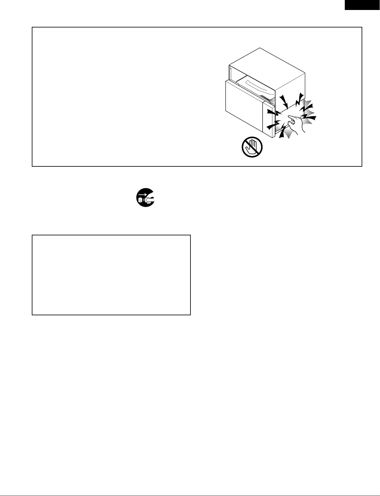
Don't Touch !
Danger High Voltage
Before Servicing
1. Disconnect the power supply cord , and then
remove outer case.
2. Open the door and block it open.
3. Discharge high voltage capacitor.
WARNING:RISK OF ELECTRIC SHOCK.
DISCHARGE THE HIGH-VOLTAGE
CAPACITOR BEFORE SERVICING.
The high-voltage capacitor remains charged about 60
seconds after the oven has been switched off. Wait for 60
seconds and then short-circuit the connection of the highvoltage capacitor (that is the connecting lead of the highvoltage rectifier) against the chassis with the use of an
insulated screwdriver.
Whenever troubleshooting is performed the power supply
must be disconnected. It may, in some cases, be necessary
to connect the power supply after the outer case has been
removed, in this event:
1. Disconnect the power supply cord, and then remove
outer case.
2. Open the door and block it open.
3. Discharge high voltage capacitor.
4. Disconnect the leads to the primary of the power
transformer.
5. Ensure that the leads remain isolated from other
components and oven chassis by using insulation tape.
6. After that procedure, reconnect the power supply cord.
When the testing is completed,
1. Disconnect the power supply cord, and then remove
outer case.
2. Open the door and block it open.
3. Discharge high voltage capacitor.
4. Reconnect the leads to the primary of the power
transformer.
5. Reinstall the outer case (cabinet).
6. Reconnect the power supply cord after the outer case is
installed.
7. Run the oven and check all functions.
After repairing
1. Reconnect all leads removed from components during
testing.
2. Reinstall the outer case (cabinet).
3. Reconnect the power supply cord after the outer case is
installed.
4. Run the oven and check all functions.
Microwave ovens should not be operated empty. To test for
the presence of microwave energy within a cavity, place a
cup of cold water on the oven turntable, close the door and
set the power to HIGH and set the microwave timer for two
(2) minutes. When the two minutes has elapsed (timer at
zero) carefully check that the water is now hot. If the water
remains cold carry out Before Servicing procedure and reexamine the connections to the component being tested.
When all service work is completed and the oven is fully
assembled, the microwave power output should be checked
and a microwave leakage test should be carried out.
1

R-408EW
MICROWAVE MEASUREMENT PROCEDURE
A. Requirements:
1) Microwave leakage limit (Power density limit): The power density of microwave radiation emitted by a microwave oven
should not exceed 1mW/cm2 at any point 5cm or more from the external surface of the oven, measured prior to acquisition
by a purchaser, and thereafter (through the useful life of the oven), 5 mW/cm2 at any point 5cm or more from the external
surface of the oven.
2) Safety interlock switches, primary interlock relay and door sensing switch shall prevent microwave radiation emission in
excess of the requirement as above mentioned. Secondary interlock switch shall prevent microwave radiation emission
in excess of 5 mW/cm2 at any point 5cm or more from the external surface of the oven.
B. Preparation for testing:
Before beginning the actual measurement of leakage, proceed as follows:
1) Make sure that the actual instrument is operating normally as specified in its instruction booklet.
Important:
Survey instruments that comply with the requirement for instrumentation as prescribed by the performance standard for
microwave ovens, 21 CFR 1030.10(c)(3)(i), must be used for testing.
2) Place the oven tray in the oven cavity.
3) Place the load of 275±15 ml (9.8 oz) of tap water initially at 20±5
O
C (68OF) in the center of the oven cavity.
The water container shall be a low form of 600 ml (20 oz) beaker with an inside diameter of approx. 8.5 cm (3-1/2 in.) and
made of an electrically nonconductive material such as glass or plastic.
The placing of this standard load in the oven is important not only to protect the oven, but also to insure that any leakage
is measured accurately.
4) Set the cooking control on Full Power Cooking Mode.
5) Close the door and select a cook cycle of several minutes. If the water begins to boil before the survey is completed, replace
it with 275 ml of cool water.
C. Leakage test:
Closed-door leakage test (microwave measurement):
1) Grasp the probe of the survey instrument and hold it perpendicular to the gap between the door and the body of the oven.
2) Move the probe slowly, not faster than 1 in./sec. (2.5 cm/sec.) along the gap, watching for the maximum indication on the
meter.
3) Check for leakage at the door screen, sheet metal seams and other accessible positions where the continuity of the metal
has been breached (eg., around the switches, indicator, and vents).
While testing for leakage around the door, pull the door away from the front of the oven as far as is permitted by the closed
latch assembly.
4) Measure carefully at the point of highest leakage and make sure that the highest leakage is no greater than 4mW/cm2,
and that the secondary interlock switch does turn the oven OFF before any door movement.
NOTE: After servicing, record data on service invoice and microwave leakage report.
2
SUPPLEMENTAL SERVICE MANUAL
R-408EW
MICROWAVE OVEN
R-408EW
FOREWORD
This Manual has been prepared to provide Sharp Electronics Corp.
Service Personnel with Operation and Service Information for the SHARP
MICROWAVE OVEN, R-408EW.
The model R-408EW is quite similar to base models R-409EW/R-410EK/
EW (Ref.# S21M160R409EE).
It is recommended that service personnel carefully study the entire text of
this manual so that they will be qualified to render satisfactory customer
service.
Check the interlock switches and the door seal carefully. Special attention
should be given to avoid electrical shock and microwave radiation hazard.
WARNING
Never operate the oven until the following points are ensured:
(A) The door is tightly closed.
(B) The door brackets and hinges are not defective.
(C) The door packing is not damaged.
(D) The door is not deformed or warped.
(E) There is no other visible damage with the oven.
PRODUCT DESCRIPTION
GENERAL INFORMATION
OPERATION
TROUBLESHOOTING GUIDE AND
TEST PROCEDURE
TOUCH CONTROL PANEL
COMPONENT REPLACEMENT
AND ADJUSTMENT PROCEDURE
WIRING DIAGRAM
Servicing and repair work must be carried out only by trained service
personnel.
DANGER
Certain initial parts are intentionally not grounded and present
a risk of electrical shock only during servicing. Service personnel - Do not contact the following parts while the appliance is
energized;
High Voltage Capacitor, Power Transformer, Magnetron, High
Voltage Rectifier Assembly, High Voltage Harness;
If provided, Vent Hood, Fan assembly, Cooling Fan Motor.
All the parts marked “*” on parts list are used at voltages more than
250V.
Removal of the outer wrap gives access to voltage above 250V.
All the parts marked “∆” on parts list may cause undue microwave
exposure, by themselves, or when they are damaged, loosened or
removed.
SHARP ELECTRONICS CORPORATION
PARTS LIST
SHARP PLAZA, MAHWAH,
NEW JERSEY 07430-2135
3
R-408EW
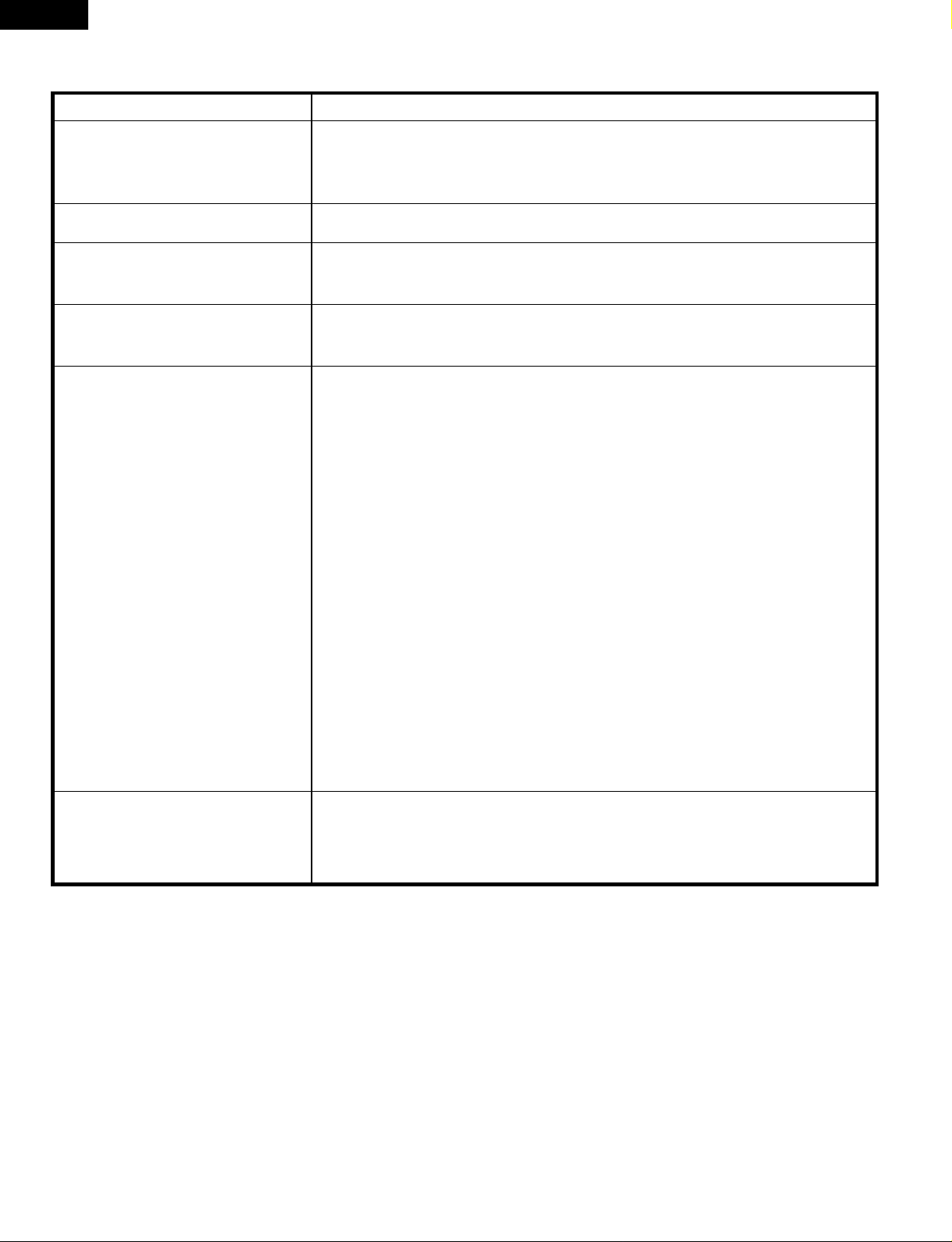
SPECIFICATION
ITEM DESCRIPTION
Power Requirements 120 Volts
13.8 Amperes, 1650 watts
60 Hertz
Single phase, 3 wire grounded
Power Output 1200 watts (IEC 705 TEST PROCEDURE)
Operating frequency of 2450MHz
Case Dimensions Width 21-21/32"
Height 12-3/8"
Depth 18-7/16"
Cooking Cavity Dimensions Width 15-23/32"
Height 9-21/32"
1.6 Cubic Feet Depth 17-7/8"
Control Complement Touch Control System
Clock ( 1:00 - 12:59 )
Timer (0 - 99 min. 99 seconds)
Microwave Power for Variable Cooking
Repetition Rate;
P-HI .................................................. Full power throughout the cooking time
P-90 ....................................................................approx. 90% of Full Power
P-80 ....................................................................approx. 80% of Full Power
P-70 ....................................................................approx. 70% of Full Power
P-60 ....................................................................approx. 60% of Full Power
P-50 ....................................................................approx. 50% of Full Power
P-40 ....................................................................approx. 40% of Full Power
P-30 ....................................................................approx. 30% of Full Power
P-20 ....................................................................approx. 20% of Full Power
P-10 ....................................................................approx. 10% of Full Power
P-0......................................................No power throughout the cooking time
BEVERAGE pad, POPCORN pad, MINUTE PLUS pad, INSTANT ACTION pads
COMPU DEFROST pads, Number selection pads Power Level pad, Timer/Clock
pad,Stop/Clear pad, START pad, Keep warm & Reheat
Oven Cavity Light Yes
Safety Standard UL Listed FCC Authorized
DHHS Rules, CFR, Title 21, Chapter 1, Subchapter J
GENERAL INFORMATION
GROUNDING INSTRUCTIONS
This oven is equipped with a three prong grounding plug. It must be plugged into a wall receptacle that is properly installed
and grounded in accordance with the National Electrical Code and local codes and ordinances.
In the event of an electrical short circuit, grounding reduces the risk of electric shock by providing an escape wire for the electric
current.
WARNING: Improper use of the grounding plug can result in a risk of electric shock.
Electrical Requirements
The electrical requirements are a 120 volt 60 Hz, AC only,
15 or 20 amp. fused electrical supply. It is recommended that a separate circuit serving only this appliance be provided. When
installing this appliance, observe all applicable codes and ordinances.
A short power-supply cord is provided to reduce risks of becoming entangled in or tripping over a longer cord.
Where a two-pronged wall-receptacle is encountered, it is the personal responsibility and obligation of the customer to contact
4
 Loading...