


 Loading...
 4
4
SUPPLEMENTAL 


R-1514
PRECAUTIONS TO BE OBSERVED BEFORE AND DURING SERVICING TO AVOID POSSIBLE EXPOSURE TO EXCESSIVE MICROWAVE ENERGY
(a)Do not operate or allow the oven to be operated with the door open.
(b)Make the following safety checks on all ovens to be serviced before activating the magnetron or other microwave source, and make repairs as necessary: (1) interlock operation, (2) proper door closing, (3) seal and sealing surfaces (arcing, wear, and other damage), (4) damage to or loosening of hinges and latches,
(5) evidence of dropping or abuse.
(c)Before turning on microwave power for any service test or inspection within the microwave generating compartments, check the magnetron, wave guide or transmission line, and cavity for proper alignment, integrity, and connections.
(d)Any defective or misadjusted components in the interlock, monitor, door seal, and microwave generation and transmission systems shall be repaired, replaced, or adjusted by procedures described in this manual before the oven is released to the owner.
(e)A microwave leakage check to verify compliance with the Federal Performance Standard should be performed on each oven prior to release to the owner.
BEFORE SERVICING
Before servicing an operative unit, perform a microwave emission check as per the Microwave Measurement Procedure outlined in this service manual.
If microwave emissions level is in excess of the specified limit, contact SHARP ELECTRONICS CORPORATION immediately @1-800-237-4277.
If the unit operates with the door open, service person should 1) tell the user not to operate the oven and 2) contact SHARP ELECTRONICS CORPORATION and Food and Drug Administration's Center for Devices and Radiological Health immediately.
Service personnel should inform SHARP ELECTRONICS CORPORATION of any certified unit found with emissions in excess of 4mW/cm2. The owner of the unit should be instructed not to use the unit until the oven has been brought into compliance.
32
R-1514
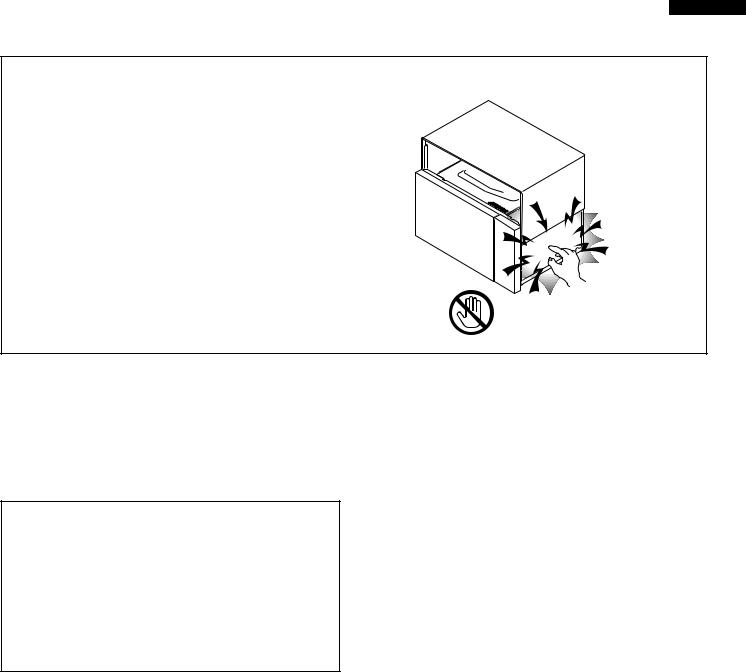
WARNING TO SERVICE PERSONNEL
Microwave ovens contain circuitry capable of producing very high voltage and current, contact with following parts may result in a severe, possibly fatal, electrical shock.
(Example)
High Voltage Capacitor, High Voltage Power Trans-
former, Magnetron, High Voltage Rectifier Assem-
bly, High Voltage Harness etc.. Read the Service Manual carefully and follow all
instructions.
Don't Touch ! Danger High Voltage
Before Servicing
1.Disconnect the power supply cord , and then remove outer case.
2.Open the door and block it open.
3.Discharge high voltage capacitor.
WARNING:RISK OF ELECTRIC SHOCK. DISCHARGE THE HIGH-VOLTAGE CAPACITOR BEFORE SERVICING.
The high-voltage capacitor remains charged about 60 seconds after the oven has been switched off. Wait for 60 seconds and then short-circuit the connection of the highvoltage capacitor (that is the connecting lead of the highvoltage rectifier) against the chassis with the use of an insulated screwdriver.
Whenever troubleshooting is performed the power supply must be disconnected. It may, in some cases, be necessary to connect the power supply after the outer case has been removed, in this event,
1.Disconnect the power supply cord, and then remove outer case.
2.Open the door and block it open.
3.Discharge high voltage capacitor.
4.Disconnect the leads to the primary of the power transformer.
5.Ensure that these leads remain isolated from other components and oven chassis by using insulation tape.
6.After that procedure, reconnect the power supply cord.
When the testing is completed,
1.Disconnect the power supply cord, and then remove outer case.
2.Open the door and block it open.
3.Discharge high voltage capacitor.
4.Reconnect the leads to the primary of the power transformer.
5.Reinstall the outer case (cabinet).
6.Reconnect the power supply cord after the outer case is installed.
7.Run the oven and check all functions.
After repairing
1.Reconnect all leads removed from components during testing.
2.Reinstall the outer case (cabinet).
3.Reconnect the power supply cord after the outer case is installed.
4.Run the oven and check all functions.
Microwave ovens should not be run empty. To test for the presence of microwave energy within a cavity, place a cup of cold water on the oven turntable, close the door and set the power to HIGH and set the microwave timer for two (2) minutes. When the two minutes has elapsed (timer at zero) carefully check that the water is now hot. If the water remains cold carry out Before Servicing procedure and reexamine the connections to the component being tested.
When all service work is completed and the oven is fully assembled, the microwave power output should be checked and microwave leakage test should be carried out.
1

R-1514
MICROWAVE MEASUREMENT PROCEDURE
A. Requirements:
1)Microwave leakage limit (Power density limit): The power density of microwave radiation emitted by a microwave oven should not exceed 1mW/cm2 at any point 5cm or more from the external surface of the oven, measured prior to acquisition by a purchaser, and thereafter (through the useful life of the oven), 5 mW/cm2 at any point 5cm or more from the external surface of the oven.
2)Safety interlock switches: Primary interlock switch shall prevent microwave radiation emission in excess of the requirement as above mentioned, secondary interlock relay and door sensing switch shall prevent microwave radiation emission in excess of 5 mW/cm2 at any point 5cm or more from the external surface of the oven.
B. Preparation for testing:
Before beginning the actual measurement of leakage, proceed as follows:
1)Make sure that the actual instrument is operating normally as specified in its instruction booklet.
Important:
Survey instruments that comply with the requirement for instrumentation as prescribed by the performance standard for microwave ovens, 21 CFR 1030.10(c)(3)(i), must be used for testing.
2)Place the oven tray in the oven cavity.
3)Place the load of 275± 15 ml (9.8 oz) of tap water initially at 20± 5˚C (68˚F) in the center of the oven cavity.
The water container shall be a low form of 600 ml (20 oz) beaker with an inside diameter of approx. 8.5 cm (3-1/2 in.) and made of an electrically nonconductive material such as glass or plastic.
The placing of this standard load in the oven is important not only to protect the oven, but also to insure that any leakage is measured accurately.
4)Set the cooking control on Full Power Cooking Mode
5)Close the door and select a cook cycle of several minutes. If the water begins to boil before the survey is completed, replace it with 275 ml of cool water.
C. Leakage test:
Closed-door leakage test (microwave measurement)
1)Grasp the probe of the survey instrument and hold it perpendicular to the gap between the door and the body of the oven.
2)Move the probe slowly, not faster than 1 in./sec. (2.5 cm/sec.) along the gap, watching for the maximum indication on the meter.
3)Check for leakage at the door screen, sheet metal seams and other accessible positions where the continuity of the metal has been breached (eg., around the switches, indicator, and vents).
While testing for leakage around the door pull the door away from the front of the oven as far as is permitted by the closed latch assembly.
4)Measure carefully at the point of highest leakage and make sure that the highest leakage is no greater than 4mW/cm2, and that the primary interlock switch and the secondary interlock relay do turn the oven OFF before any door movement.
NOTE: After servicing, record data on service invoice and microwave leakage report.
2
R-1514
SERVICE MANUAL
OVER THE RANGE
MICROWAVE OVEN
R-1514
FOREWORD
This Manual has been prepared to provide Sharp Electronics Corp. Service Personnel with Operation and Service Information for the SHARP OVER THE RANGE MICROWAVE OVEN, R-1514.
The model R-1514 are quite similar to base models R-1500 and R-1501 (Reference No. is S8123R1500X//).
It is recommended that service personnel carefully study the entire text of this manual and base model service manual so that they will be qualified to render satisfactory customer service.
Check the interlock switches and the door seal carefully. Special attention should be given to avoid electrical shock and microwave radiation hazard.
WARNING
Never operate the oven until the following points are ensured.
(A)The door is tightly closed.
(B)The door brackets and hinges are not defective.
(C)The door packing is not damaged.
(D)The door is not deformed or warped.
(E)There is not any other visible damage with the oven.
Servicing and repair work must be carried out only by trained service personnel.
DANGER
Certain initial parts are intentionally not grounded and present a risk of electrical shock only during servicing. Service personnel - Do not contact the following parts while the appliance is energized;
High Voltage Capacitor, Power Transformer, Magnetron, High Voltage Rectifier Assembly, High Voltage Harness;
If provided, Vent Hood, Fan assembly, Cooling Fan Motor.
All the parts marked “*” on parts list are used at voltages more than 250V.
Removal of the outer wrap gives access to voltage above 250V.
All the parts marked “∆ ” on parts list may cause undue microwave exposure, by themselves, or when they are damaged, loosened or removed.
SHARP ELECTRONICS CORPORATION
SHARP PLAZA, MAHWAH,
NEW JERSEY 07430-2135
3

R-1514
|
PRODUCT SPECIFICATION |
||
|
|
|
|
ITEM |
|
|
DESCRIPTION |
|
|
||
Power Requirements |
120 Volts / 14 Amperes / 1600 Watts |
||
|
60 Hertz |
|
|
|
Single phase, 3 wire grounded |
||
|
|
||
Power Output |
1000 watts (IEC TEST PROCEDURE) |
||
|
Operating frequency of 2450MHz |
||
|
|
|
|
Case Dimensions |
Width |
29-15/16" |
|
|
Height |
16-1/4" |
|
|
Depth |
15- 9/16" |
|
|
|
|
|
Cooking Cavity Dimensions |
Width |
17-1/2" |
|
|
Height |
9-7/8" |
|
1.5 Cubic Feet |
Depth |
14-15/16" |
|
|
|
|
|
Hood lamp |
2 bulbs, 20W x 2, |
Incandescent light bulbs |
|
Hood fan |
Approx. 300 C.F.M. |
||
|
|
||
Control Complement |
Touch Control System |
||
|
Clock ( 1:00 - 12:59 ) |
||
|
Timer (0 - 99 min. 99 seconds) |
||
|
Microwave Power for Variable Cooking |
||
|
Repetition Rate; |
|
|
|
P-HI .................................................. |
|
Full power throughout the cooking time |
|
P-90 .................................................................... |
|
approx. 90% of Full Power |
|
P-80 .................................................................... |
|
approx. 80% of Full Power |
|
P-70 .................................................................... |
|
approx. 70% of Full Power |
|
P-60 .................................................................... |
|
approx. 60% of Full Power |
|
P-50 .................................................................... |
|
approx. 50% of Full Power |
|
P-40 .................................................................... |
|
approx. 40% of Full Power |
|
P-30 .................................................................... |
|
approx. 30% of Full Power |
|
P-20 .................................................................... |
|
approx. 20% of Full Power |
|
P-10 .................................................................... |
|
approx. 10% of Full Power |
|
P-0 .................................................... |
|
No power throughout the cooking time |
|
KEEP WARM PLUS pad,HOT WATER pad, CUSTOM HELP pad |
||
|
INSTANT SENSOR pads, SENSOR COOK CENTER pads |
||
|
REHEAT pads, DEFROST CENTER pad, Number selection pads |
||
|
POWER LEVEL pad, TIMER / CLOCK pad |
||
|
LIGHT HI / LO button, FAN HI / LO button, |
||
|
STOP/CLEAR button, START/ MINUTE PLUS button, |
||
|
|
||
Oven Cavity Light |
20W x 1 Incandescent light bulb |
||
|
|
|
|
Safety Standard |
UL Listed |
FCC Authorized |
|
|
DHHS Rules, CFR, Title 21, Chapter 1, Subchapter J |
||
|
|
|
|
Weight |
Approx. 55 lbs. |
|
|
|
|
|
|
4
R-1514
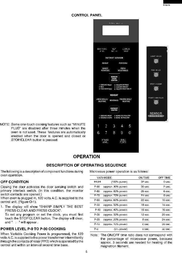
SENSOR COOKING CONDITION
Using the Sensor Cooking function, the foods are cooked or defrosted without figuring time, power level or quantity. When the oven senses enough steam from the food, it relays the information to its microprocessor which will calculate the remaining cooking time and power level needed for best results. When the food is cooked, water vapor is developed. The sensor “senses” the vapor and its resistance increases gradually. When the resistance reaches the value set according to the menu, supplementary cooking is started. The time of supplementary cooking is determined by experiment with each food category and inputted into the LSI.
An example of how sensor works (Baked potatoes):
1. Potatoes at room temperature. |
MICROWAVE |
|
|
Vapor is emitted very slowly. |
|
2. Heat |
potatoes. |
Moisture |
|
MICROWAVE |
|
AH SENSOR |
|||||
and |
humidity is |
emitted |
|||
|
|
|
|
rapidly. You can smell the aroma as it cooks.
3.Sensor detects moisture and humidity and calculates cooking time and variable power.
Cooking Sequence.
1.Operate the oven in sensor cooking mode by referring to operation manual.
NOTE: The oven should not be operated on Sensor Cooking immediately after plugging in the unit. Wait two minutes before cooking on Sensor Cooking.
2.The coil of shut-off relay (RY1) is energized, the oven lamp, turntable motor and cooling fan motor are turned on, but the power transformer is not turned on.
3.After about 32 seconds, the cook relay (RY2) is energized. The power transformer is turned on, microwave energy is produced and first stage is started.
The 32 seconds is the cooling time required to remove any vapor from the oven cavity and sensor.
NOTE: During this first stage, do not open the door or touch STOP/CLEAR pad.
4.When the sensor detects the vapor emitted from the food, the display switches over to the remaining cooking time and the timer counts down to zero.
At this time, the door may be opened to stir food, turn it or season, etc.
5.When the timer reaches zero, an audible signal sounds. The shut-off relay and cook relay are de-energized and the power transformer, oven lamp, etc. are turned off.
6.Opening the door or touching the STOP/CLEAR pad, the time of day will reappear on the display and the oven will revert to an OFF condition.
NOTE: " " indicates components with potential above 250V.
CAVITY |
MAGNETRON |
||
THERMAL CUT-OUT |
TEMPERATURE FUSE |
||
|
|
|
|
|
|
|
|
|
|
|
|
|
|
CONTROL UNIT |
|
N.O. |
COM. |
|
|
|
|
|
|
|
|
|
|
|
|
||
FUSE |
|
|
|
|
|
|
|
|
|
E2 |
|
20A |
|
|
|
|
|
|
|
|
|
|
|
|
|
A5 |
|
RY4 |
|
|
|
|
|
|
DOOR |
|
|
|
|
|
|
|
|
|
|
|
|
|
|
|
|
|
|
|
|
|
|
|
SENSING |
|
|
B5 |
|
|
RY6 |
|
|
|
|
|
SWITCH |
BLK |
HOOD FAN |
|
|
RY3 |
|
|
|
|
E1 |
|
|
|
|
|
|
|
|
RY2 |
|
||||
|
High |
|
|
|
|
|
|
|
|||
|
THERMAL |
|
|
|
|
|
|
|
F1 |
|
|
|
CUT OUT |
B7 |
|
|
|
|
|
|
SECONDARY |
|
|
|
|
N.C. |
|
|
|
|
|
|
|||
GRN |
|
|
|
RY5 |
|
OVEN LAMP |
INTERLOCK |
F2 |
SENSOR |
||
120 V AC. GND |
|
B9 |
CAPACITOR |
|
RELAY |
|
RELAY |
|
|||
|
|
Low |
|
|
|
RY1 |
|
|
|
|
|
|
|
|
HOOD |
|
|
|
|
|
|
|
|
|
|
|
|
|
|
|
|
|
|
|
|
60 Hz |
|
|
|
|
|
|
|
|
|
F3 |
AH |
|
|
|
|
|
|
|
|
|
|
|
|
WHT |
|
HOOD |
A1 |
A3 |
B1 |
B3 |
N.O. |
COM. |
|
|
|
|
MOTOR |
|
|
|
|
|
|
|
|
|
|
|
|
|
|
|
|
|
|
|
|
|
|
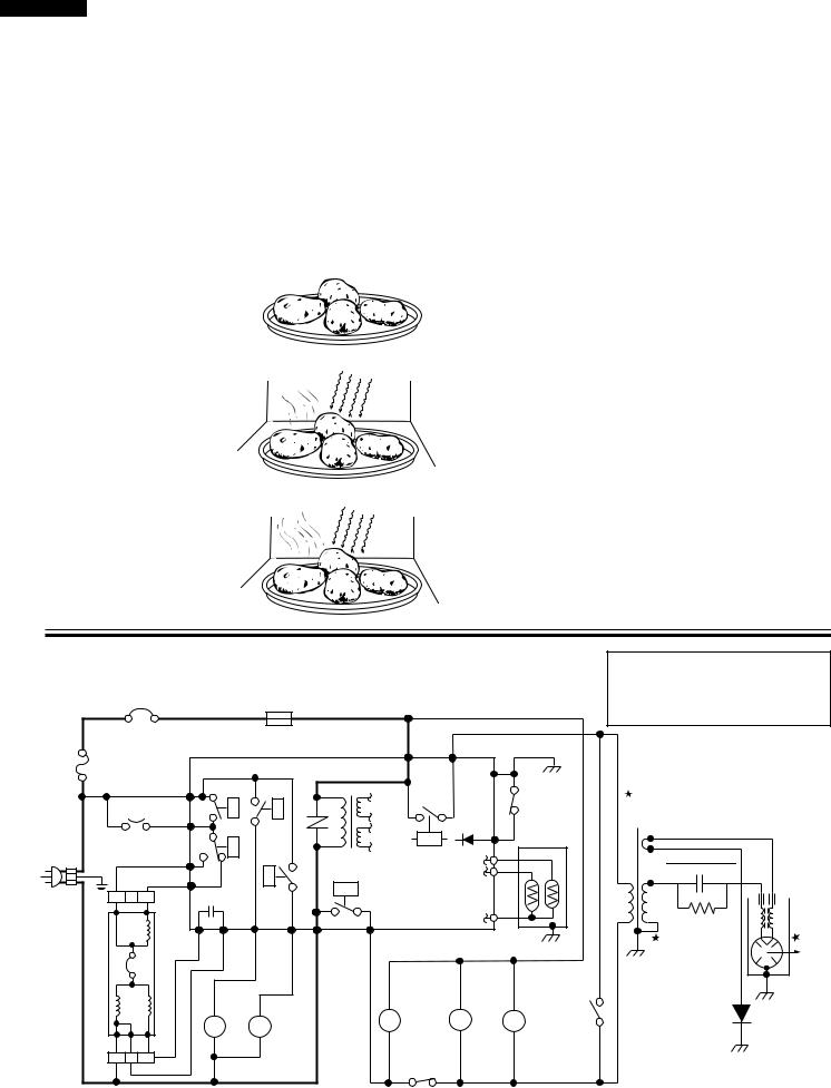
SCHEMATIC NOTE: CONDITION OF OVEN
1.DOOR CLOSED.
2.CLOCK APPEARS ON DISPLAY.
POWER
TRANSFORMER


 MAGNETRON HIGH VOLTAGE
CAPACITOR 0.94 F/ AC2300V
HOOD
LAMP
HL HL
OL
OVEN LAMP
TTM
TURNTABLE MOTOR
FM
FAN MOTOR
SWITCH
MONITOR
 HIGH VOLTAGE
RECTIFIER
PRIMARY
INTERLOCK
SWITCH
Figure O-1. Oven Schematic-Off Condition
6

R-1514
CAVITY |
MAGNETRON |
||
THERMAL CUT-OUT |
TEMPERATURE FUSE |
||
|
|
|
|
|
|
|
|
|
|
|
|
SCHEMATIC
NOTE: CONDITION OF OVEN
1.DOOR CLOSED.
2.COOKING TIME PROGRAMMED.
3.VARIABLE COOKING CONTROL "HIGH".
4."START" BUTTON PRESSED.
|
|
|
|
|
|
CONTROL UNIT |
|
N.O. |
COM. |
|
|
|
|
|
|
|
|
|
|
|
|
||
FUSE |
|
|
|
|
|
|
|
|
|
E2 |
|
20A |
|
|
|
|
|
|
|
|
|
|
|
|
|
A5 |
|
RY4 |
|
|
|
|
|
|
DOOR |
|
|
|
|
|
|
|
|
|
|
|
|
|
|
|
|
|
|
|
|
|
|
|
SENSING |
|
|
B5 |
|
|
RY6 |
|
|
|
|
|
SWITCH |
BLK |
HOOD FAN |
|
|
RY3 |
|
|
|
|
E1 |
|
|
|
|
|
|
|
|
RY2 |
|
||||
|
High |
|
|
|
|
|
|
|
|||
|
THERMAL |
|
|
|
|
|
|
|
F1 |
|
|
|
CUT OUT |
B7 |
|
|
|
|
|
|
SECONDARY |
|
|
|
|
N.C. |
|
|
|
|
|
|
|||
GRN |
|
|
|
RY5 |
|
OVEN LAMP |
INTERLOCK |
F2 |
SENSOR |
||
120 V AC. GND |
|
B9 |
CAPACITOR |
|
RELAY |
|
RELAY |
|
|||
|
|
Low |
|
|
|
RY1 |
|
|
|
|
|
|
|
|
HOOD |
|
|
|
|
|
|
|
|
|
|
|
|
|
|
|
|
|
|
|
|
60 Hz |
|
|
|
|
|
|
|
|
|
F3 |
AH |
|
|
|
|
|
|
|
|
|
|
|
|
WHT |
|
HOOD |
A1 |
A3 |
B1 |
B3 |
N.O. |
COM. |
|
|
|
|
MOTOR |
|
|
|
|
|
|
|
|
|
|
|
|
|
|
|
|
|
|
|
|
|
|
|
HOOD |
|
LAMPOVEN |
|
TURNTABLE MOTOR |
FAN MOTOR |
MONITOR SWITCH |
|
LAMP |
OL |
|
TTM |
|
FM |
|
HL |
HL |
|
|
|
|||
|
|
|
|
|
|
PRIMARY
INTERLOCK
SWITCH
Figure O-2. Oven Schematic-Cooking Condition
POWER |
TRANSFORMER |
MAGNETRON |
HIGH VOLTAGE |
CAPACITOR |
0.94 F/ AC2300V |
HIGH VOLTAGE |
RECTIFIER |
TROUBLESHOOTING GUIDE
Never touch any part in the circuit with your hand or an uninsulated tool while the power supply is connected.
When troubleshooting the microwave oven, it is helpful to follow the Sequence of Operation in performing the checks. Many of the possible causes of trouble will require that a specific test be performed. These tests are given a procedure letter which will be found in the "Test Procedure "section.
IMPORTANT:
If the oven becomes inoperative because of a blown monitor fuse, check the monitor switch, relay (RY1) secondary interlock relay (RY2), door sensing switch and primary interlock switch before replacing the monitor fuse. If monitor fuse is replaced, the monitor switch must also be replaced. Use part FFS-BA016/KiT as an assembly.
IMPORTANT:
Whenever troubleshooting is performed with the power supply cord disconnected. It may in, some cases, be necessary to connect the power supply cord after the outer case has been removed, in this event,
1.Disconnect the power supply cord, and then remove outer case.
2.Open the door and block it open.
3.Discharge high voltage capacitor.
4.Disconnect the leads to the primary of the power transformer.
5.Ensure that the leads remain isolated from other components and oven chassis by using insulation tape.
6.After that procedure, reconnect the power supply cord. When the testing is completed
1.Disconnect the power supply cord, and then remove outer case.
2.Open the door and block it open.
3.Discharge high voltage capacitor.
4.Reconnect the leads to the primary of the power transformer.
5.Reinstall the outer case (cabinet).
6.Reconnect the power supply cord after the outer case is installed.
7.Run the oven and check all functions.
7

R-1514
|
TEST PROCEDURE |
L |
Q |
CK |
|
|
POSSIBLE CAUSE |
|
|
WIRING |
|
CONDITION |
UNITCONTROL |
SENSORAH |
ORSHORTEDOPENED |
||
PROBLEM |
|||||
|
AND |
|
|
|
|
|
DEFECTIVE PARTS |
|
|
|
|
|
|
|
|
|
|
SENSOR |
The oven stops and "ERROR" is displayed or does not end during Sensor Cooking |
|
|
|
|
condition. (Oven does not shut off after a cup of water is boiling by Sensor Cooking.) |
|
|
|
||
COOKING |
|
|
|
|
|
|
|
|
|
||
CONDITION |
Oven stops at 32 seconds after starting. |
|
|
|
|
|
|
|
|
|
NOTE: For additional troubleshooting procedures, please refer back to the R-1500/1501/R1505/1506 base model Service Manual.
TEST PROCEDURES
PROCEDURE
COMPONENT TEST
LETTER
LTOUCH CONTROL PANEL ASSEMBLY TEST
The touch control panel consists of circuits including semiconductors such as LSI, ICs, etc. Therefore, unlike conventional microwave ovens, proper maintenance cannot be performed with only a voltmeter and ohmmeter. In this service manual, the touch control panel assembly is divided into two units, Control Unit and Key Unit, and also the Control Unit is divided into two units, LSI Unit and Power Unit, and troubleshooting by unit replacement is described according to the symptoms indicated.
Before testing,
1)Disconnect the power supply cord, and then remove outer case. Refer to procedure of “ HOOD EXHAUST LOUVER REMOVAL ”, “ REMOVAL OF OVEN FROM WALL ” and “ OUTER CASE REMOVAL ”.
2)Open the door and block it open.
3)To discharge high voltage capacitor, wait for 60 seconds.
4)Remove two (2) screws holding the hood intake duct R to the ovencavity top plate and the base plate R. And remove the hood intake duct R.
5)Disconnect the leads to the primary of the power transformer.
6)Ensure that these leads remain isolated from other components and oven chassis by using insulation tape.
1.Key Unit. NOTE ;
1)Check key unit ribbon connection before replacement.
2)Re-install the hood intake duct R with two (2) screws.
3)Re-install the outer case (cabinet).
4)Reconnect the power supply cord after the outer case is installed.
5)Run the oven and check all functions.
The following symptoms indicate a defective key unit.
a)When touching the pads, a certain pad produces no signal at all.
b)When touching a number pad, two figures or more are displayed.
c)When touching the pads, sometimes a pad produces no signal. If the key unit is defective.
1) Disconnect the power supply cord, and then remove outer case. 2) Open the door and block it open.
8
Loading...