


O V E R T H E R A N G E M I C R O W A V E O V E N
INSTALLATION INSTRUCTIONS
Please read all instructions thoroughly before installing the Over the Range Microwave Oven/Hood System. Two people are recommended to install this product.
If a new electrical outlet is required, its installation should be completed by a qualified electrician before the Microwave Oven/Hood is installed. See 3 ELECTRICAL GROUNDING INSTRUCTIONS on page 2.
1 MOUNTING SPACE
This Microwave Oven/Hood requires a mounting space on a wall |
12" |
as shown in Figure 1. |
|
For proper installation and servicing, a 2-inch space is necessary between the top of the range backsplash and the bottom of the Microwave Oven/Hood system.
2 WALL CONSTRUCTION
This Microwave Oven/Hood should be mounted against and supported by a flat vertical wall. The wall must be flat for proper installation. If the wall is not flat, use spacers to fill in the gaps.
Wall construction should be a minimum of 2" x 4" wood studding and 3/8" or more thick dry wall or plaster/lath. The mounting surfaces must be capable of supporting weight of 110 pounds—the oven and contents—AND the weight of all items which would normally be stored in the top cabinet above the unit.
The unit should be attached to a minimum of one 2" x 4" wall stud.
To find the location of the studs, one of the following methods may be used:
A.Use a stud finder, a magnetic device which locates the nails in the stud.
B.Use a hammer to tap lightly across the mounting surface to find a solid sound. This will indicate stud location.
The center of the stud can be located by probing the wall with a small nail to find the edges of the stud and then placing a mark halfway between the edges. The center of any adjacent studs will normally be 16" or 24" to either side of this mark.
NOTE: In the event that the unit will be unable to be supported by any stud, it will be necessary to use special care in the placement of the toggle bolts and top cabinet screws. See Wall Template for details. The top cabinet should be tested to ensure it is securely attached to the wall. Place extra weight up to 110 pounds inside the top cabinet to test the support.
30" |
|
|
15.5" |
|
|
At least 2" |
30" or more from |
|
cooking surface |
||
|
||
Backsplash |
|
66" or more from floor
Figure 1
16" or 24" |
2"x 4" Wood Studs |
|
3/8" Dry Wall or Plaster/lath
Figure 2
1
3 ELECTRICAL GROUNDING INSTRUCTIONS
This appliance must be grounded. This oven is equipped with a cord having a grounding wire with a grounding plug. It must be plugged into a wall receptacle that is properly installed and grounded in accordance with the National Electrical Code and local codes and ordinances. In the event of an electrical short circuit, grounding reduces risk of electric shock by providing an escape wire for the electric current.
WARNING - Improper use of the grounding plug can result in a risk of electric shock.
The oven is equipped with a 3-prong grounding plug. DO NOT UNDER ANY CIRCUMSTANCES CUT OR REMOVE THE GROUNDING PIN FROM THE PLUG.
The Power Supply Cord and plug must be connected to a separate 120 Volt AC, 60 Hz, 15 Amp, or more branch circuit, single grounded receptacle. The receptacle should be located inside the cabinet directly above the Microwave Oven/ Hood mounting location.
NOTE:
1.If you have any questions about the grounding or electrical instructions, consult a qualified electrician or serviceperson.
2.Neither Sharp nor the dealer can accept any liability for damage to the oven or personal injury resulting from failure to observe the correct electrical connection procedures.
Grounded
Receptacle
Opening for
Power Cord
Figure 3
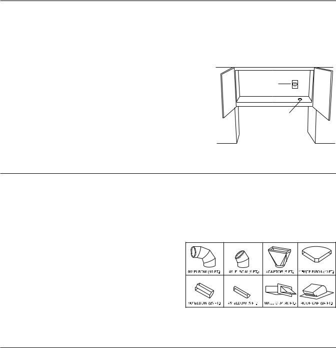
4 HOOD EXHAUST DUCT
When the hood is vented to the outside, a hood exhaust duct is required. All ductwork must be metal; absolutely do not use plastic duct. Check that all connections are made securely. Please read the following carefully:
Exhaust connection: The hood exhaust has been designed to connect to a standard 31/4" x 10" rectangular duct. If round duct is required, a rectangular-to-round adapter must be used.
Rear exhaust: If a rear or horizontal exhaust is to be used, care should be taken to align the exhaust with the space between the studs, or wall should be prepared at the time it is constructed by leaving enough space between wall studs to accommodate exhaust.
Maximum duct length: For satisfactory air movement, the total duct length of 31/4" X 10" rectangular or 6" diameter round duct should not exceed 140 feet.
Elbows, adapters, wall, roof caps, etc. present additional resistance to air flow and are equivalent to a section of straight duct which is longer than their actual physical size. When calculating the total length, add the equivalent lengths of all transitions and adapters plus the length of all straight duct sections. Figure 4 shows the approximate feet of equivalent length of some typical ductwork parts. Use the values in parentheses for calculating air flow resistance equivalent, which should total less than 140 feet.
Figure 4
5 TOOLS RECOMMENDED FOR INSTALLATION
• Phillips Screwdriver |
• Measure |
• Electric Drill |
• 1/2”, 5/8” and 3/32” Drill Bits |
• Scissors |
• 1-1/2” Wood Bit or Metal Hole Cutter (if metal cabinet is used) |
• Pencil |
• Saw to cut exhaust opening (if needed) |
• Tape |
• Protective Drop Cloth for product and range - you may also use carton for protection |
2
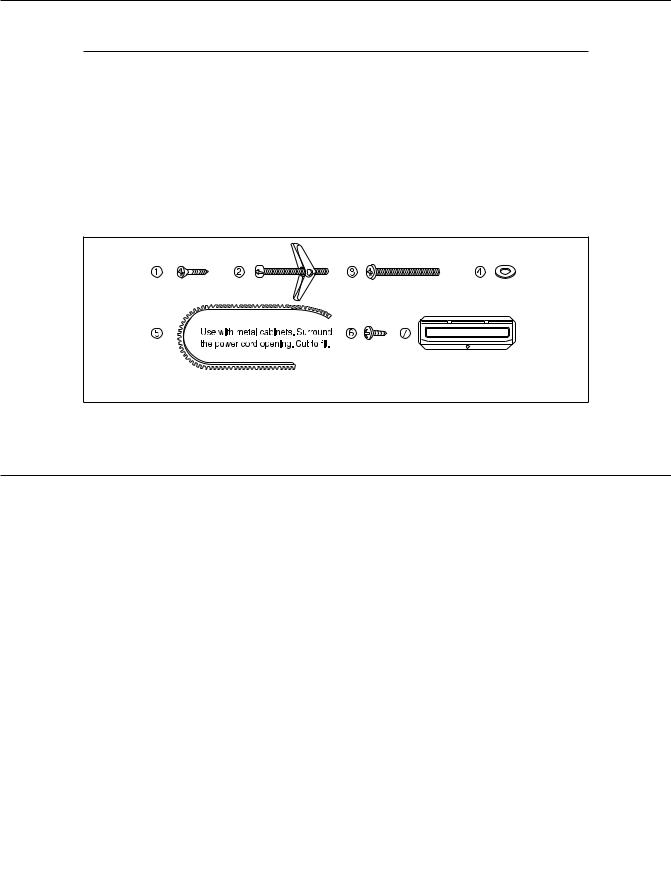
6 INSTALLATION HARDWARE
The INSTALLATION HARDWARE: items 1 - 7 packed with the oven should contain the following:.
ITEM |
NAME |
QUANTITY |
PART CODE |
|
|
|
|
1 |
Wood Screw 5 x 30 mm |
6 |
XTSS750P35000 |
2 |
Toggle Bolt #10 - 24 x 50 mm |
4 |
LX-BZ0195WRE0 |
3 |
Top Cabinet Screw 5 x 60 mm |
2 |
XBPS750P60000 |
4 |
Flat Washer 30 mm diameter |
2 |
XWH750-16300 |
5 |
Grommet |
1 |
LBSHC0040MRE0 |
6 |
Tapping Screw 4 x 12 mm |
1 |
XOTS740P12000 |
7 |
Exhaust Damper Assembly |
1 |
FFTA-B004MRK0 |
Parts shown not to common scale.
Figure 5
7 PREPARATION OF THE OVEN
Note: This step does not apply to R-1881LSY
Utilization of the carton may make installation easier.
1.Open the bottom of the carton, remove oven and all packing materials.
2.CHECK THE OVEN.
Check the oven for any damage, such as misaligned or bent door, damaged door seals and sealing surfaces, broken or loose door hinges and latches and dents inside the cavity or on the door. If there is any damage, do not operate the oven and contact your dealer or SHARP AUTHORIZED SERVICER.
3.Place carton upside down as shown in Figure 6-1.
4.Using cutting line around the carton, cut into two pieces (A) and (BC). See Figure 6-2.
5.Cut the remaining portion (BC) into portion (B) and portion (C) according to cutting line. See Figure 6-3.
(B) |
(B) |
|
|
|
(C) |
(C) |
|
|
|
|
Cutting line |
|
|
|
Top side |
(A) |
|
(A) |
|
|
|
|
Figure 6-1 |
Figure 6-2 |
|
Figure 6-3 |
3
 Loading...