


Notice for Users in the USA
FCC Statement
WARNING - FCC Regulations state that any unauthorized changes or modifications to this equipment not expressly approved by the manufacturer could void the user’s authority to operate this equipment.
Note: This equipment has been tested and found to comply with the limits for a Class B digital device pursuant to Part 15 of the FCC Rules.
These limits are designed to provide reasonable protection against harmful interference in a residential installation. This equipment generates, uses and can radiate radio frequency energy and, if not installed and used in accordance with the instructions, may cause harmful interference to radio communications. However, there is no guarantee that interference will not occur in a particular installation. If this equipment does cause harmful interference to radio or television reception, which can be determined by turning the equipment off and on, the user is encouraged to try to correct the interference by one or more of the following measures:
Reorient or relocate the receiving antenna.
Increase the distance between the equipment and receiver.
Connect the equipment into an outlet on a circuit different from that to which the receiver is connected.
Consult the dealer or an experienced radio/TV technician for help.
A shielded I/F cable and included cables with ferrite cores are required to insure compliance with FCC regulation for Class B computing equipment.
*As an ENERGY STAR® Partner, SHARP has determined that this product meets the ENERGY STAR® guidelines for energy efficiency.
Declaration of Conformity
SHARP PERSONAL COMPUTER, PC-A800 Series
This device complies with part 15 of the FCC rules. Operation is subject to the following conditions:(1)this device may not cause harmful interference, and (2) this device must accept any interference received, including interference that may cause undesired operation.
Responsible Party: SHARP ELECTRONICS CORPORATION
Sharp Plaza, Mahwah, New Jersey 07430-2135
TEL: 1-800-BE-SHARP
i

About the Modem
This equipment complies with Part 68 of FCC rules. On the bottom of this equipment is a label that contains, among other information, the FCC registration number and ringer equivalence number (REN) for this equipment. If requested, this information must be provided to the telephone company.
The modem jack of this equipment complies with Sub-part F of Part 68 of FCC rules.
The REN is used to determine the quantity of devices which may be connected to the telephone line. Excessive RENs on the telephone line may result in the devices not ringing in response to an incoming call. In most, but not all areas, the sum of the RENs should not exceed five (5.0). To be certain of the number of devices that may be connected to the line, as determined by the total RENs contact the telephone company to determine the maximum REN for the calling areas.
If the terminal equipment causes harm to the telephone network, the telephone company will notify you in advance that temporary discontinuance of service may be required. But if advance notice isn't practical, the telephone company will notify the customer as soon as possible. Also, you will be advised of your right to file a complaint with the FCC if you believe it necessary.
The telephone company may make changes in its facilities, equipment, operations, or procedures that could affect the operation of the equipment. If this happens, the telephone company will provide advance notice in order for you to make the necessary modifications in order to maintain uninterrupted service.
If trouble is experienced with this equipment, please contact Sharp Electronics Corp. for repair and (or) warranty information (Refer to the end of this section). If the trouble is causing harm to the telephone network, the telephone company may request you remove the equipment from the network until the problem is resolved.
The equipment cannot be used on public coin service provided by the telephone company. Connection to Party Line Service is subject to state tariffs. (Contact the state public utility commission, public service commission or corporation commission for information.)
ii

The Telephone Consumer Protection Act of 1991 makes it unlawful for any person to use a computer or other electronic device, including fax machines, to send any message unless such message clearly contains in a margin at the top or bottom of each transmitted page or on the first page of the transmission, the date and time it is sent and an identification of the business or other entity, or other individual sending the message and the telephone number of the sending machine or such business, other entity, or individual. (The telephone number provided may not be a 900 number or any other number for which charges exceed local or long-distance transmission charges.) To program this information, refer to the manual of the communication software.
CAUTION: DISCONNECT TELEPHONE LINES BEFORE ACCESSING THE MODEM CARD.
Copyright
It is the intent of Sharp that this product be used in full compliance with the copyright laws of the United States and that prior permission be obtained from copyright owners whenever necessary.
Product Information and Customer Assistance
For Product Information and Customer Assistance:
Call: 1-800-BE-SHARP (237-4277)
Sharp Electronics Corp.
Sharp Plaza, Mahwah, NJ 07430-2135
Home Page: http://www.sharp-usa.com
E-mail address: pcsupport@sharpsec.com
CompuServe: Go Sharp
iii

Notice for Users in Canada
About the Modem
The Industry Canada label identifies certified equipment.
This certification means that the equipment meet certain telecommunications network protective, operational and safety requirements. The department does not guarantee the equipment will operate to the user's satisfaction.
Before installing this equipment, users should ensure that it is permissible to be connected to the facilities of the local telecommunications company.
The equipment must also be installed using an acceptable method of connection. In some cases, the company's inside wiring associated with a single line individual service may be extended by means of a certified connector assembly (telephone extension cord). The customer should be aware that compliance with the above conditions may not prevent degradation of service in some situations.
Repairs to certified equipment should be made by an authorized Canadian maintenance facility designated by the supplier. Any repairs or alterations made by the user to this equipment, or equipment malfunctions, may give the telecommunications company cause to request the user to disconnect the equipment.
Users should ensure for their own protection that the electrical ground connections of the power utility, telephone lines and internal metallic water pipe system, if present, are connected together. This precaution may be particularly important in rural areas.
CAUTION Users should not attempt to make such connections themselves, but should contact the appropriate electric inspection authority, or electrician, as appropriate.
“The Ringer Equivalence Number (REN) assigned to each terminal device denotes the percentage of the total load to be connected to a telephone loop which is used by the device. To prevent overloading, the termination on a loop may consist of any combination of devices subject only to the requirement that the total of Ringer Equivalence Number of all the devices does not exceed 5.”
iv

CAUTION:
DISCONNECT TELEPHONE LINES BEFORE ACCESSING THE MODEM CARD.
ATTENTION:
DEBRANCHER LES LIGNES TELEPHONIQUES AVANT D’ENLEVER CE COUVRICLE.
Product Information and Customer Assistance
For Product Information and Customer Assistance:
Call: 1-905-890-2100 |
(Toronto Area) |
1-800-56-SHARP |
(Outside Toronto) |
Sharp Electronics of Canada Ltd.
335 Britannia Road East,
Mississauga, Ontario, L4Z 1W9
Canada
v

Notice for Users in Australia
Service Inquiries
Please contact your dealer for service if required or contact Sharp Corporation of Australia on 1-800-807820 (free call) for referral to your nearest Sharp authorised Service Centre. Details can be found on the warranty card inserted with the documentation.
Copyright
Copyright may exist in material you wish to record. Copying or broadcasting such material without permission of the relevant licensees or owners of the copyright is prohibited by law.
SHARP is not in a position to authorise the copying or broadcasting of copyright materials and nothing in this OPERATION MANUAL should be implied as giving that authority.
vi

Notice for Users in the UK
IMPORTANT
The wires in this mains lead are coloured in accordance with the following code:
BLUE: Neutral BROWN: Live
As the colours of the wires in the mains lead of this apparatus may not correspond with the coloured markings identifying the terminals in your plug proceed as follows.
The wire which is coloured BLUE must be connected to the terminal which is marked with the letter N or coloured black.
The wire which is coloured BROWN must be connected to the terminal which is marked with the letter L or coloured red.
This apparatus must be protected by a 3A fuse in the mains plug or distribution board.
Copyright
Recording and playback of any material may require consent, which SHARP is unable to give. Please refer particularly to the provisions of the Copyright Act 1956, the Dramatic and Musical Performers Protection Act 1958, the Performers Protection Acts 1963 and 1972 and to any subsequent statutory enactments and orders.
vii

Notice for Users in Europe
This equipment complies with the requirements of Directives 89/336/EEC and 73/23/EEC as amended by 93/68/EEC.
Dieses Gerät entspricht den Anforderungen der EG-Richtlinien 89/336/EWG und 73/23/EWG mit Änderung 93/68/EWG.
Ce matériel répond aux exigences contenues dans les directives 89/336/CEE et 73/23/CEE modifiées par la directive 93/68/CEE.
Dit apparaat voldoet aan de eisen van de richtlijnen 89/336/EEG en 73/23/EEG, gewijzigd door 93/68/EEG.
Dette udstyr overholder kravene i direktiv nr. 89/336/EEC og 73/23/EEC med tillæg nr. 93/68/EEC.
Quest' apparecchio è conforme ai requisiti delle direttive 89/336/EEC e 73/23/EEC, come emendata dalla direttiva 93/68/EEC.
Η εγκατασταση |
αυτη |
ανταποκρινεται |
στιζ απαιτησειζ |
των |
οδηγιων |
τηζ |
|
Ευρωπα |
ïκηζ |
Ενωσηζ |
89/336/EOK κατ 73/23/EOK, óπωζ |
οι |
κανονισµοι |
αυτοι |
|
συµπληρωθηκαν |
|
απ |
ó την οδηγια |
93/68/EOK. |
|
|
|
Este equipamento obedece às exigências das directivas 89/336/CEE e 73/23/CEE, na sua versão corrigida pela directiva 93/68/CEE.
Este aparato satisface las exigencias de las Directivas 89/336/CEE y 73/23/CEE, modificadas por medio de la 93/68/CEE.
Denna utrustning uppfyller kraven enligt riktlinjerna 89/336/EEC och 73/23/EEC så som komplette ras av 93/68/EEC.
Dette produktet oppfyller betingelsene i direktivene 89/336/EEC og 73/23/EEC i endringen 93/68/EEC.
Tämä laite täyttää direktiivien 89/336/EEC ja 73/23/EEC vaatimukset, joita on muutettu direktiivillä 93/68/EEC.
viii

CAUTION:
TO PREVENT ELECTRICAL SHOCK, DISCONNECT THE AC CORD AND THE BATTERY BEFORE SERVICING.
CAUTION:
FOR A COMPLETE ELECTRICAL DISCONNECTION, PULL OUT THE MAIN PLUG AND THE BATTERY.
VORSICHT:
UM DIE STROMZUFUHR VOLLSTÄNDIG ZU UNTERBRECHEN, DEN NETZSTECKER HERAUSZIEHEN UND DIE BATTERIE ÈNTFERNEN.
ATTENTION:
POUR UN ARRET TOTAL DU SYSTEME, DECONNECTEZ LA PRISE DE COURANT SECTEUR ET LA BATTERIE.
VARNING:
FÖR TOTAL ELEKTRISK URKOPPLING, KOPPLA UR KONTAKTEN OCH TA UR BATTERIET.
PRECAUCION:
PARA UNA COMPLETA DESCONEXION ELECTRICA DESENCHUFE LA CLAVIJA DE LA RED Y LA BATERIA.
ix

Safety Precautions
General
•Follow all cautions and instructions which may be marked on the computer.
•Except as described elsewhere in this manual, refer all servicing to qualified personnel. Immediately shut off the computer and seek servicing under the following conditions:
•when the power cord or plug is damaged or frayed
•if liquid has been spilled on the computer
•if the computer has been dropped or the cabinet has been damaged
Location
•Do not expose the computer to direct sunlight.
•Try to avoid dusty environments.
•Keep the computer away from any magnetic devices and TVs.
•Keep the computer away from excessive humidity or fluids such as rain, snow, water spray, juice, coffee, steam, etc.
•Do not move the computer from an extremely cold place to an extremely warm place. A temperature difference of more than 10° C (18° F) will cause condensation inside the unit, which may cause damage.
•Do not block or cover slots or openings on the cabinet. These protect the computer from overheating.
•Care should be exercised when using on heat sensitive surfaces or your lap as the base of this computer will get hot.
•Do not smoke near your computer.
Usage
•Never push any objects of any kind into cabinet openings. They may touch dangerous voltage points or short parts that could result in fire or electrical shock.
•Turn off the computer before installing or removing a peripheral device (except when connecting USB devices and PC cards).
•Check the AC power cord and power connectors periodically for damage. Replace the power cord immediately if damage is found.
•Never subject your computer to sudden shocks or extreme vibration.
x
•Do not drop the computer nor hit it with other equipment.
•Do not scratch the surface of the LCD screen.
•Turn off the computer and disconnect the AC power cord before cleaning.
Battery Pack Precautions
Handling
•Never put the battery pack in a fire, as it could explode and cause injury.
•Do not attempt to open or alter the battery pack.
•Do not place the battery where it might get hotter than 60° C (140° F).
•Do not allow metal objects such as jewelry to short across the battery terminals, as it could heat up and explode.
•Do not allow liquids to come in contact with the battery pack.
•Avoid dropping the pack or other violent shock.
•Do not solder anything to the battery terminals.
Charging
•Charge the battery pack only with the AC adapter included with your computer or an optional one.
Discharging
•Do not use the battery pack for any purpose other than powering the computer.
Storage
•Store the battery pack in a cool and dry place. Never allow the temperature to exceed 60° C (140° F) during storage.
•Recharge the battery pack after storage, before use.
xi

Modem Precautions
•Never install telephone wiring during a lightning storm.
•Never install telephone jacks in wet locations unless the jack is specifically designed for wet locations.
•Never touch uninsulated telephone wires or terminals unless the telephone line has been disconnected at the network interface.
•Use caution when installing or modifying telephone lines.
•Avoid using the telephone during a lightning storm. There may be a remote risk of electric shock from lightning.
•Do not use the telephone to report a gas leak while in the vicinity of the leak.
xii

About This Manual
Notice
Information in this manual is subject to change without notice and does not represent a commitment on the part of SHARP Corporation.
SHARP Corporation shall not be liable for technical or editorial errors or omissions contained herein; nor for incidental or consequential damages resulting from the furnishing, performance, or use of this material.
SHARP strongly recommends that separate permanent written records be kept of all important data. Data may be lost or altered in virtually any electronic memory product under certain circumstances. Therefore, SHARP assumes no responsibility for data lost or otherwise rendered unusable whether as a result of improper use, repairs, defects, battery replacement, use after the specified battery life has expired, or any other causes.
SHARP assumes no responsibility directly or indirectly, for financial losses or claims from third persons resulting from the use of this product and any of its functions, such as stolen credit card numbers, the loss of or alteration of stored data, etc.
Edition
1st Edition, September 1999.
Copyright
© 1999 SHARP Corporation
This document contains or refers to proprietary information which is protected by copyright. All rights are reserved. Copying or other reproduction of this document is prohibited without the prior written permission of SHARP Corporation.
Trademarks
Pentium is a registered trademark, and Celeron is a trademark, of Intel Corporation. IBM and PS/2 are trademarks of International Business Machines Corporation.
Microsoft, MS-DOS, Windows, and the Windows Logo are registered trademarks of Microsoft Corporation.
Sound Blaster is a trademark of Creative Technology Ltd.
All other brand and product names are trademarks or registered trademarks of their respective holders.
xiii
Recording Important Information
For future reference, please record the following information in the spaces provided below.
Model Number:
Serial Number:
Date of purchase:
Dealer’s Name:
Place of purchase:
Password:
The serial number is printed on a sticker located on the bottom of the computer.
xiv
Manual Conventions
This manual uses a set of style conventions described below.
Notes and Cautions are italicized with icons:
A note icon informs you of a special technique or information that may help you perform a task or better understand a process.
A caution icon alerts you to something that may cause problems or damage to hardware, software or data.
Key Labels on the Keyboard, when referred to in the instructions, are shown in boldface:
Press Enter to continue.
When two or more keys are pressed simultaneously, the key labels are separated by a plus (+) sign:
Restart your computer by pressing Ctrl+Alt+Delete.
When necessary, important key combinations are shown in graphics:
Sample Entries are shown in upper cases of different typeface. In the following case, press the Enter key after you type the command:
C:\>DIR A: Enter
Words/Texts on Screen, such as window titles or possible parameters, are italicized:
Double-click this icon to display the Power Properties window. Set the item to Enabled.
Screens reproduced in this manual may differ slightly from the screens you see on your computer.
Section Titles in other parts of this manual are italicized:
Refer to Infrared Communication section in Chapter 5.
xv

Table of Contents
Notice for Users in the USA ....................................................................................... |
i |
Notice for Users in Canada....................................................................................... |
iv |
Notice for Users in Australia .................................................................................... |
vi |
Notice for Users in the UK ...................................................................................... |
vii |
Notice for Users in Europe ..................................................................................... |
viii |
Safety Precautions...................................................................................................... |
x |
About This Manual ................................................................................................. |
xiii |
Recording Important Information ........................................................................... |
xiv |
Manual Conventions ................................................................................................ |
xv |
Table of Contents.................................................................................................... |
xvi |
Overview of Computer............................................................................................ |
xix |
Fast Start |
1-1 |
Connecting AC Power ............................................................................................ |
1-1 |
Setting Up Windows 98.......................................................................................... |
1-3 |
Turning Off Your Computer ................................................................................... |
1-4 |
Basic Operations |
2-1 |
Powering the Computer .......................................................................................... |
2-1 |
Resetting the System............................................................................................... |
2-3 |
Using the Keyboard ................................................................................................ |
2-4 |
Using the Glide Pad ................................................................................................ |
2-7 |
Reading the Status Indicators.................................................................................. |
2-8 |
Adjusting the Display ............................................................................................. |
2-9 |
Controlling Audio ................................................................................................. |
2-11 |
Using the Drives ................................................................................................... |
2-12 |
Installing a Drive in the Drive Bay ....................................................................... |
2-14 |
Using the CD-ROM Drive .................................................................................... |
2-15 |
Using the Floppy Disk Drive Externally............................................................... |
2-16 |
Battery and Power Management |
3-1 |
Battery Pack............................................................................................................ |
3-1 |
Battery Low Warnings............................................................................................ |
3-3 |
Battery Conditioning............................................................................................... |
3-4 |
Changing a Battery Pack......................................................................................... |
3-5 |
xvi

Programmable Power Management |
........................................................................ 3-6 |
Power Management Hot-keys .............................................................................. |
3-10 |
Connecting Peripherals |
4-1 |
Using Peripheral Devices ....................................................................................... |
4-1 |
Connecting Peripherals Overview.......................................................................... |
4-2 |
Using PC Cards...................................................................................................... |
4-3 |
Connecting an External Monitor ............................................................................ |
4-6 |
Connecting Headphones....................................................................................... |
4-10 |
Connecting USB Devices..................................................................................... |
4-10 |
Connecting a Printer............................................................................................. |
4-11 |
Communication Functions |
5-1 |
Infrared Communication ........................................................................................ |
5-1 |
Built-in Modem(may not available in some countries) .......................................... |
5-4 |
|
|
Changing or Adding Options |
6-1 |
Using the Recovery CD.......................................................................................... |
6-1 |
Adding a Memory Module ..................................................................................... |
6-3 |
Using the Optional Port Replicator ........................................................................ |
6-5 |
|
|
Security Features |
7-1 |
Passwords............................................................................................................... |
7-1 |
Using a Security Cable ........................................................................................... |
7-4 |
|
|
Setup Utility |
8-1 |
Running the Setup Utility....................................................................................... |
8-1 |
Main Page .............................................................................................................. |
8-3 |
Advanced Page....................................................................................................... |
8-4 |
Security Page.......................................................................................................... |
8-5 |
Power Page............................................................................................................. |
8-6 |
Boot Page ............................................................................................................... |
8-7 |
Exit Page ................................................................................................................ |
8-7 |
xvii

Appendices
Appendix 1: Troubleshooting ................................................................................ |
A-1 |
Appendix 2: Care & Maintenance ......................................................................... |
A-8 |
Appendix 3: Specifications.................................................................................. |
A-10 |
Index
Index ................................................................................................................Index-1
xviii
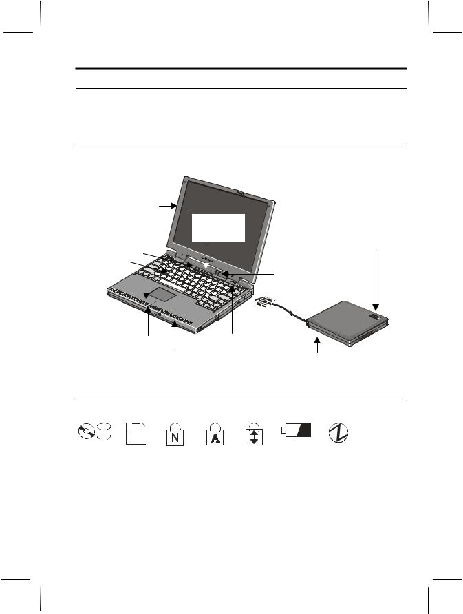
Overview of Computer
In the following diagram, the labels in italics refer to the chapter and page number in this manual where you can find more information. The actual appearance of your computer may be slightly different depending on the model.
Front View
LCD screen |
|
See 2-9 |
System status |
|
|
|
indicators |
Microphone |
See 2-8 |
Release latch for floppy |
|
See 2-11 |
disk drive |
Keyboard |
Battery & power |
See 2-4 |
|
|
indicators |
|
See 2-2 |
Glide pad 


See 2-7
Glide pad buttons |
Power button |
|
See 2-7 |
Speaker |
|
|
Floppy disk drive in |
|
|
See 2-11 |
|
floppy disk drive box
See 2-13, 2-16
Front View Markings
|
|
|
|
|
|
|
|
|
|
|
|
|
|
|
|
|
|
|
|
|
|
|
|
|
|
|
|
|
|
CD or |
Floppy |
|
|
|
|
|
|
|
|
|
|
|||
Num |
Caps |
Scroll |
Battery |
Power |
||||||||||
Hard disk |
disk |
lock |
|
lock |
lock |
indicator |
Indicator |
|||||||
activity |
activity |
|
|
|
|
|
|
|
|
|
|
|||
xix
Right Side View
PC card slot
See 4-3
Drive bay with CD-ROM drive installed
See 2-15
|
|
|
|
|
|
|
|
|
|
|
|
|
|
|
|
|
|
|
|
|
|
|
|
|
|
|
|
|
|
|
|
|
|
|
|
|
|
|
|
|
|
|
|
|
|
|
|
|
|
PC card eject |
|
|
Manual tray eject |
||||||
Drive activity |
|||||||||
button |
indicator |
button (recessed) |
|||||||
See 4-4 |
|
|
|
|
|
|
|
||
|
|
|
|
|
|
|
|||
|
|
|
|
Eject tray button |
|||||
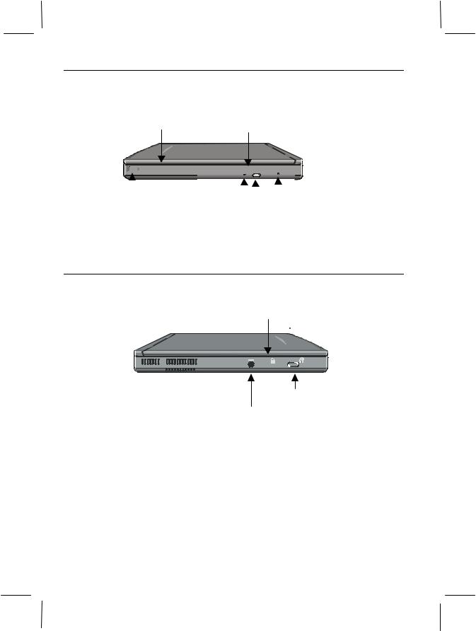
Left Side View
Slot for security cable
See 7-4
 K
K
Battery lock button
AC adapter jack
See 1-1
xx
Rear View
|
|
Modem |
Monitor port |
USB port |
||||||
|
|
jack |
||||||||
|
|
See 5-4 |
See 4-6 |
See 4-10 |
||||||
|
|
|
|
|
|
|
|
|
|
|
|
|
|
|
|
|
|
|
|
|
|
|
|
|
|
|
|
|
|
|
|
|
|
|
|
|
|
|
|
|
|
|
|
|
|
|
|
|
|
|
|
|
|
|
Parallel/FDD port |
|
Headphone jack |
|
See 4-11 |
Infrared port |
||
|
See 5-1 |
See 4-10 |
|
Bottom View
Memory module compartment
Port replicator docking See 6-4
connector |
|
See 6-6 |
|
Drive bay lock latch |
Reset switch |
(recessed) |
|
|
See 2-3 |
Battery
See 3-1, 3-5
CD-ROM drive installed in drive bay
See 2-14
xxi
CHAPTER 1
1
Fast Start
Your new computer is ready to use as soon as you unpack it from the box. If you’re familiar with computers, follow the instructions in this chapter to get your system up and running in just a few minutes. If this is your first computer, you should read through the entire Operation Manual before starting the system.
Connecting AC Power
Run your computer the first time using AC power, rather than battery power. This ensures that you will not lose power while you complete the Windows setup operation.
•Use only the AC adapter that was supplied with your computer,
or supplied by your computer vendor. You can damage your computer if you try to use an AC adapter that is not approved for use with this system.
•When removing the AC power cord from a wall outlet, grip the plug and pull it from the socket. Never remove the power cord from the outlet by pulling on the cord. Always grip the plug.
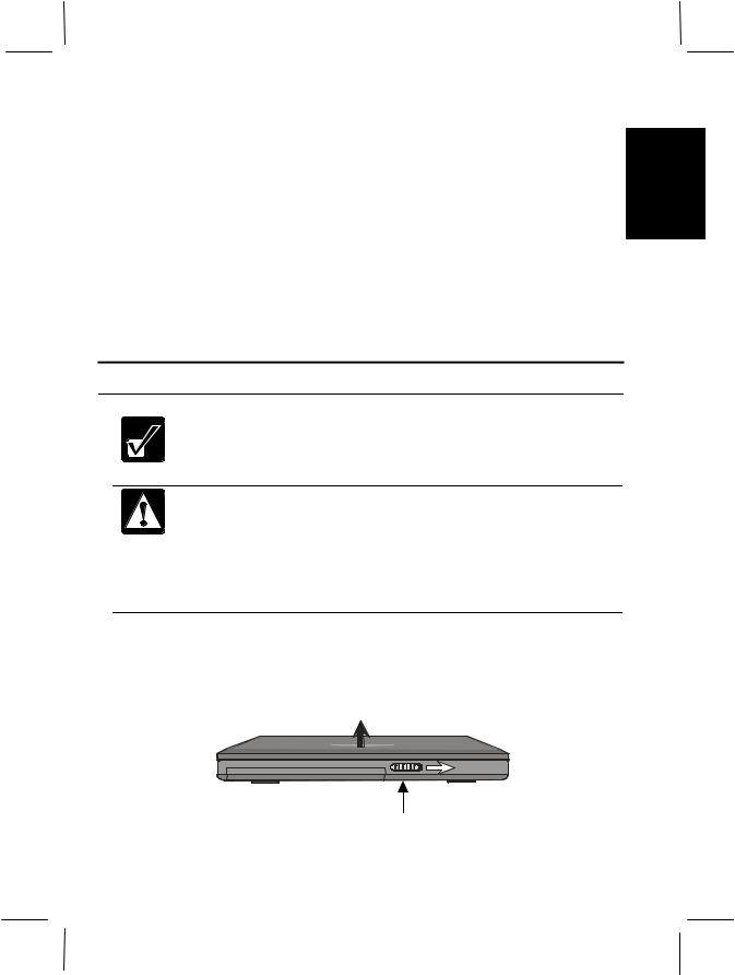
Place your computer on a flat working surface and follow the steps below.
1.On the front edge of the computer, slide the cover latch to the right and raise the cover.
Cover latch
1-1
2.Plug the cable from the AC adapter into the AC adapter jack on the left side of the computer.
3.Connect the power cord to the AC adapter.
4.Plug the power cord into a suitable power outlet. The orange battery charge 1 indicator turns on when you connect AC power.
Battery charge |
Power button |
and power |
|
indicators |
|
AC adapter jack
AC adapter
To power outlet
5.Press the power button located just above the Pause button on the keyboard. The green power indicator turns on when the power is turned on.
6.After a logo screen and several seconds of power-on testing, the computer loads the Windows 98 operating system.
7.As this is the first time you have used your computer, Windows begins by running the Windows 98 Setup Wizard.
1-2
Setting Up Windows 98
Windows 98 is pre-installed on your computer, including the special drivers and
software used by built-in components such as the audio and video system, the 1 modem, and the PC card slot. The Windows Setup program lets you enter personal
data such as your name, the date and time in your location, and so on. It takes just a few minutes to complete. The setup process has four steps:
•Getting started
This section asks for your name.
•Registration
This section configures your modem
•Windows License
This section asks you to accept the Windows License Agreement and to enter the Windows Product Key
•Final Settings
This section checks the date and time in your location, and then completes the configuration of your system
Once you start the system for the first time, be sure to complete the setup program. Windows does not display the Setup Wizard the next time you turn on the computer.
About Windows Properties Dialog Boxes
In this manual you are often asked to open a Component Properties dialog box, such as the Modem Properties dialog box, or the Display Properties dialog box. These dialog boxes let you make changes to the configuration and operation of the component by clicking check boxes or selecting radio buttons. To open a Property dialog box, click the Start button in the taskbar at the foot of the Windows display. Select Settings - Control Panel. In the Control Panel window, double-click on an icon to display a Properties dialog box, or similar window, for the component or feature represented by that icon. Some of the Properties dialog boxes that are used to configure components in your computer include:
•
•
•
Display
Modem
Mouse
1-3
•
•
1 •
PC Card
Power Management
System
Turning Off Your Computer
When you’re finished using your computer, turn it off with the following steps:
1.Click the Start button in the taskbar and click on Shut Down from the Start menu.
2.In the Shut Down Windows dialog box, check the Shut down item and then click the OK button. The power indicator turns off.
3.Close the cover to keep the screen and keyboard clean and protected.
You can shut down the computer with the power button using the steps below:
1.From the Start menu, select Settings – Control Panel and double-click the
Power Management icon.
2.In the Power Management Properties dialog box, click the Advanced tab.
3.Select Shutdown in the drop down menu for “When I press the power button on my computer”, and then click Apply and OK.
If you have not saved a file, a dialog box appears prompting you to save the file.
•Don’t turn off your computer if status indicators show that the
computer is still accessing data on the hard disk drive, the floppy disk drive or the CD-ROM drive. Data may be lost or damaged.
•After turning off the computer wait at least five seconds before turning the computer back on. Turning the computer off and on without a pause can damage the system.
Since this is your first session using the computer, it’s a good idea to leave the AC adapter connected to the computer until the internal battery is fully charged. The orange battery charge indicator changes to green when the battery is fully charged.
1-4

CHAPTER 2
Basic Operations |
2 |
This chapter describes some of the basic operations of your computer such as using the keyboard, adjusting the display, and so on.
Powering the Computer
You can operate your computer by using the AC adapter to connect to a suitable power outlet. You can also power the computer by the internal Lithium-Ion battery.
Whenever you use the AC adapter to power the computer, the internal battery automatically begins recharging. Recharging continues whether the computer is turned on or off.
Refer to Chapter 3 Battery and Power Management for a full description of battery charging and related information.
2-1

Power and Battery Indicators
For proper operations it is important to understand the operation of the power and 2 battery indicators located beside the right-side hinge of the upper cover.
Indicator Meanings
Green Power Indicator |
|
|
Icon |
Lamp State |
Status |
|
Turned on |
Computer is turned on |
|
Turned off |
Computer is turned off |
|
Slow blinking |
Computer is in Standby |
|
mode |
|
|
|
|
Tri-color (green/red/orange) Battery Indicator |
||
Icon |
Lamp State |
Status |
|
Turned on orange |
Battery is charging |
|
Turned on green |
Battery is fully charged |
|
Turned on red |
Battery low warning |
|
Flashing red |
Critical battery warning |
|
|
Abnormal condition – for |
|
Flashing orange |
example the battery may be |
|
|
installed incorrectly |
2-2
Resetting the System
You may need to reset the system after adding hardware or software so that your computer recognizes newly installed devices or software. When the message appears after the installation, click OK, Yes, etc., to restart Windows 98.
You can also restart Windows 98 from the Start menu. Select Shut Down, then
Restart. |
2 |
|
Warm Boot (Software Reset)
If the system is locked up because of a software problem, you can reset or reboot the system by pressing the Ctrl+Alt+Del keys simultaneously. Press the Ctrl+Alt+Del keys again to restart the computer.
Resetting may cause data loss. Use the software reset only if the normal Windows 98 Shut Down does not work because of software malfunction. Although resetting does not damage the system, you may lose the data you are processing.
Power Switch
You can turn off the computer with the power switch if the system has hardware or software problems so that you can’t use the Windows Shut Down command or the software reset. In this case, you need to hold the power button down for more than four seconds.
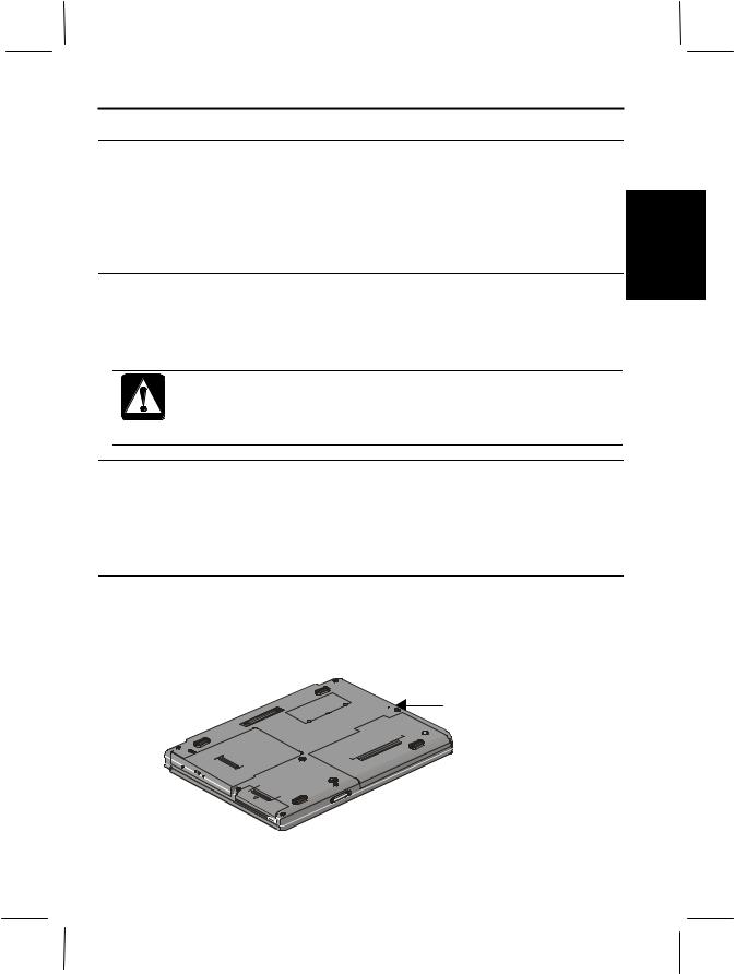
Reset Switch
If all other methods fail, you can reset the computer by pressing the hardware reset switch. The hardware reset switch is in a recessed location on the base of the computer. Activate the switch with a straightened paper clip or similar implement.
Reset switch (recessed)
2-3
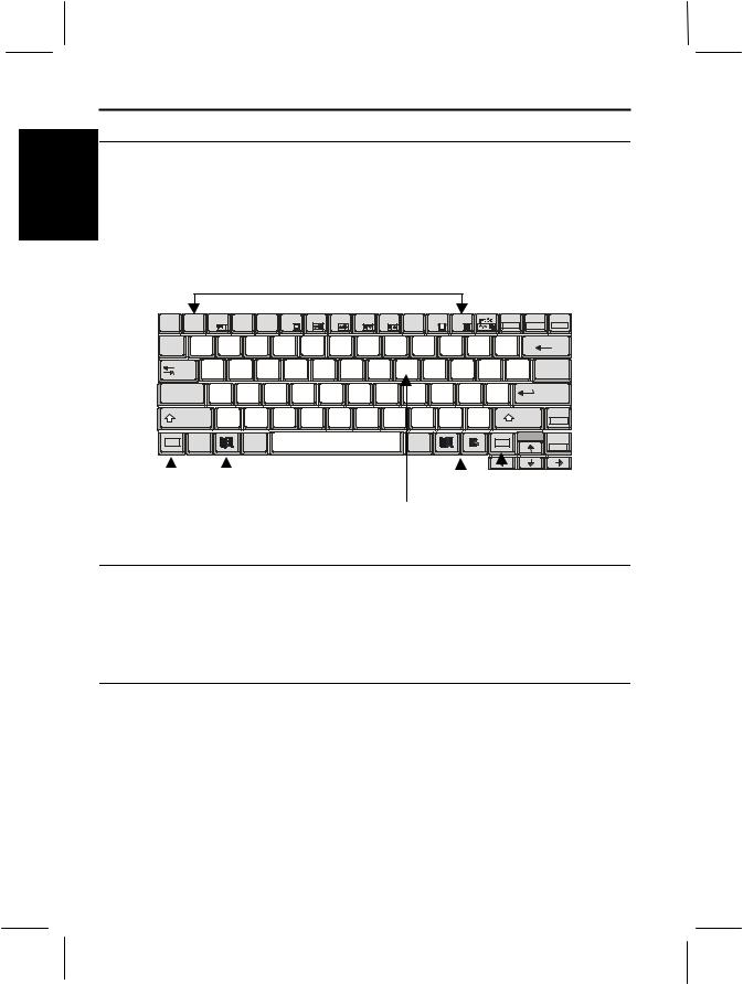
Using the Keyboard
The built-in keyboard includes all the functions that you find on a full-sized
2 keyboard. In addition, the keyboard has built-in hot keys that you can use to control some of the functions of the computer.
The illustration below shows the location of some important keys on your keyboard.
Function Keys
Esc |
F1 |
F2 |
F3 |
F4 |
F5 |
F6 |
F7 |
F8 |
F9 |
|
F10 |
F11 |
|
F12 |
|
|
Pause |
Insert |
Delete |
|
|
|
|
|
|
|
|
|
|
|
|
|
|
|
|
|
Break |
NumLk |
ScrLk |
~ |
! |
|
@ |
# |
$ |
% |
^ |
& 7 |
* 8 |
|
( 9 |
) |
* |
|
|
_ |
+ |
Backspace |
|
|
|
|
|
- |
|||||||||||||||
` |
1 |
|
2 |
3 |
4 |
5 |
6 |
7 |
8 |
|
9 |
0 |
|
|
|
= |
|
|
|
Tab |
|
Q |
W |
E |
R |
T |
|
Y |
U 4 |
I 5 |
O 6 |
|
P |
- |
{ |
} |
| |
|
|
|
|
|
[ |
] |
|
||||||||||||||
|
|
|
|
|
|
|
|
|
|
|
|
|
|
|
|
\ |
|
||
Caps |
|
A |
S |
D |
|
F |
G |
H |
J 1 |
|
K 2 |
L 3 |
: |
|
+ |
" |
Enter |
||
|
|
|
|
|
|
|
|||||||||||||
Lock |
|
|
|
|
|
|
|
|
|
|
|
|
|
;- |
|
|
' |
|
|
|
|
|
|
|
|
|
|
|
|
|
|
|
|
|
|
|
|
||
Shift |
|
Z |
X |
C |
V |
B |
N |
M |
0 |
< |
> |
|
. |
|
? / |
Shift |
Pg Up |
||
|
, |
. |
|
|
|
/ |
Home |
||||||||||||
|
|
|
|
|
|
|
|
|
|
|
|
|
|
|
|
||||
Fn |
Ctrl |
|
Alt |
|
|
|
|
|
|
Alt |
|
|
|
|
|
Fn |
|
Pg Dn |
|
|
|
|
|
|
|
|
|
|
|
|
|
|
End |
||||||
|
|
|
|
|
|
|
|
|
|
|
|
|
|
|
|
|
|
|
|
|
|
|
|
|
|
|
|
FN Key |
|
|
|
|
|
||
|
|
|
FN Key |
||||
|
|
Windows |
|
|
|||
|
|
Keypad |
Windows |
||||
|
|
Key |
|||||
|
|
|
|
Area |
Keys |
||
Function Keys
On their own, the operation of the function keys is usually determined by the software application that you are running. In combination with the Fn key they create hot-keys that you can use to control some of the computer functions. Icons embossed on the function key keycaps indicate the hot-key function.
Embedded Keypad
The numeric keypad is embedded in some of the right-side alphanumeric keys. The keypad functions are embossed in the upper right corner of the keypad keycaps. You activate the embedded numeric keypad by pressing the Num Lk key (press Fn+Insert). Repeat the keystroke to turn off the embedded keypad.
2-4

Windows Keys
There are two different Windows keys as shown below. The keyboard repeats the Windows Start key on either side of the Space bar.
Windows Start Key. This key opens the Windows Start menu |
|
on the taskbar. In combination with other keys it provides |
|
short cuts to some Windows functions. See Windows help for |
2 |
more information. |
Windows Pull-down Menu key. When an item is selected and this key is pressed, it pulls down a menu if one is available. It is similar to the right click of a mouse or glide pad.
Fn (Function) Key Combinations
You can activate hot-key system controls and various embedded keystrokes by holding down one of the two Fn keys and then pressing any of the keys embossed with an icon or boxed text on the lower half of the key.
|
+ |
|
Pops up an information box in the upper left |
Fn |
F2 |
corner of the screen – see the section Pop Up |
|
|
|
|
Power Management Information Box below |
|
+ |
|
Switch display between the built-in screen, an |
Fn |
F5 |
external monitor, and a simultaneous display – |
|
|
|
|
see Chapter 4 Connecting Peripherals |
|
+ |
F6 |
Press keys to decrease screen brightness – see |
Fn |
Adjusting the Display below |
||
|
+ |
F7 |
Press keys to increase screen brightness – see |
Fn |
Adjusting the Display below |
||
|
+ |
F8 |
Press keys to decrease the audio volume – see |
Fn |
|
Controlling the Audio below |
|
|
+ |
F9 |
Press keys to increase the audio volume – see |
Fn |
|
Controlling the Audio below |
Fn |
+ |
F11 |
Turns off the display backlight on the built-in screen – see Adjusting the Display below
|
+ |
F12 |
Puts the system into suspend mode – see About |
Fn |
Standby Mode in Chapter 3. |
2-5
 Loading...