


Ver. 2.0 _ Mar 15, 2010
INSTALLATION AND USER MANUAL
FOR SHARP PHOTOVOLTAIC MODULES
NU-U240F1 / NU-U235F1 / NU-U235F3 / NU-U230F3
ND-U230C1 / ND-U224C1 / ND-U216C1
ND-224UC1 / ND-220UC1 / ND-216UC1 / ND-208UC1 / ND-200UC1
NT-175UC1 / NT-170UC1 / NE-170UC1 / NE-165UC1
IMPORTANT SAFETY INSTRUCTIONS
This manual contains important safety instructions for the PV module that must be followed during the installation and the maintenance of PV modules.
PLEASE READ THIS MANUAL CAREFULLY BEFORE INSTALLING OR USING THE MODULES.
PLEASE PASS ALONG THIS MANUAL TO YOUR CUSTOMER.
A) GENERAL MANUAL
A-1. INTRODUCTION
Thank you for choosing a Sharp photovoltaic (PV) module. This Installation Manual contains essential information for electrical and mechanical installation that you must know before installing Sharp photovoltaic modules. These modules are UL listed (UL 1703). This Manual also contains safety information you need to be familiar with. All the information described in this Manual is the intellectual property of Sharp and is based on the technologies and experience that have been acquired and accumulated over the long history of Sharp. Sharp does not assume responsibility and expressly disclaims liability for loss, damage, or expense arising out of or in any way connected with installation, operation, use or maintenance of PV modules. No responsibility is assumed by Sharp for any infringement of patents or other rights of third parties that may result from use of PV modules. Sharp reserves the right to make changes to the product, specifications or Installation Manual without prior notice. Refer to module limited warranty information provided at the end of this manual.
A-2. GENERAL INFORMATION
(INCLUDING WARNING AND SAFETY)
The installation of PV modules requires a great degree of skill and should only be performed by qualified licensed professionals, including licensed contractors and licensed electricians. Please be aware that there is a serious risk of various types of injury occurring during the installation including the risk of electric shock. These Sharp PV modules are equipped with a permanently attached special cable assembly for ease of installation which does not require special assembly.
<GENERAL WARNING >
1.PV modules are heavy. Handle with care.
2.Before you attempt to install, wire, operate and maintain the PV module, please make sure that you completely understand the information described in this Installation Manual.
3.Contact with electrically active parts of a PV module such as terminals can result in burns, sparks and lethal shock whether the PV modules are connected or not.
4.PV modules produce electricity when sufficient sunlight or other light source illuminates the module. When modules are connected in series, voltage is cumulative. When modules are connected in parallel, current is cumulative. PV systems can produce high voltage and current which could present an increased hazard and may cause serious injury or death.
5.Do not connect PV modules directly to motor loads. Variation in PV module output power as a function of solar irradiance may damage directly-connected loads. For example,
1:In the case of a brushless motor, the lock function may become active and the motor may be damaged;
2:In the case of a brush type motor, the coil may be damaged.
<GENERAL SAFETY >
1.Install PV modules and ground frames and other metal components in accordance with applicable codes and regulations.
2.PV modules should be installed and maintained by qualified personnel. Only installation/service personnel should have access to the PV module installation site.
3.Keep children away from PV modules.
4. |
Prior to installation, do not store modules outdoors or in a |
|
damp environment to prevent glass from damage due to white |
|
efflorescence. |
5. |
When PV modules are installed on roofs or any other structures |
|
above ground, appropriate safety practices should be followed |
|
and appropriate safety equipment should be used in order to avoid |
possible safety hazards. Note that the installation of PV modules on some roof types may require the addition of fireproofing, as required by local building/fire codes.
6.Roof mounted PV modules are to be mounted over a fire resistant roof.
7.Only PV modules with the same cell size should be connected in series.
8.Follow all safety precautions of other components used in the system.
9.In order to avoid risk of injury or electrical shock, do not allow anyone to handle damaged PV modules if the person is unqualified or has limited knowledge of PV modules. Place defective PV modules in cartons so PV cells are completely shaded, because a defective PV module or module with broken glass may generate power even if it is removed from the system.
10.When installing PV modules in a readily accessible location, the National Electrical Code (NEC) 690.33 requires installing the additional locking sleeve (Multi-Contact part # PV-SSH4) on the connector. Note that this sleeve is not included with the module. This requirement is for circuits operating in excess of 30 volts, nominal, maximum system voltage for DC or 30 volts for AC circuits.
11.Avoid uneven shade on the PV module surface. Shaded cells may become hot (“hot spot” phenomenon) which may result in permanent damage to the module (e.g., solder joints may peel off).
12.Do not clean the glass surface with chemicals. Do not let water stay on the glass surfaces of PV modules for a long time. This creates a risk of permanent damage to the glass, such as white efflorescence, otherwise known as “glass disease,” which may cause reduced power output.
13.To avoid dirt accumulation or white efflorescence due to water accumulation, do not install PV modules horizontally (flat).
14.In high snow load regions, appropriate measures are to be taken so that PV module frames (on lower edges of the modules) will not be damaged.
- 1 - |
Installation Manual for PV Modules |
Ver. 2.0 _ Mar 15, 2010
15.Do not expose PV modules to sunlight concentrated with mirrors, lenses or other means.
16.Turn off inverters and circuit breakers immediately, should a problem occur.
17.The maximum open circuit voltage must not be greater than the specified maximum system voltage. Voltage is proportional to the number of PV modules in series and is affected by weather conditions. For strings connected in parallel take proper measures to block reverse current flow.
18.Wiring and grounding method of the frame of arrays shall comply with applicable codes and standards, e.g., the NEC, article 250.
19.Grounding shall be achieved through securement to the array frame. The array frame shall be grounded in accordance with NEC Article 250.
<HANDLING SAFETY >
1.Do not expose the PV module to excessive loads on the surface of the PV module or twist the frame. The glass may break.
2.Do not stand or step on the PV module. The glass may be slippery, and there is a risk of injury or electric shock if glass is broken.
3.Do not hit or put excessive load on the glass or back sheet. PV cells may break.
4.To avoid damage to the back sheet, do not scratch or hit the back sheet.
5.To avoid damage to the terminal box and electricity leakage or shock, do not hit the terminal box; do not pull the interconnect cables; do not scratch the interconnect cable.
6.Avoid the connector from scratching or impacting the back sheet of the module.
7.Install connector such that it is not exposed to direct sunlight.
8.Do not twist the interconnect cable excessively.
9.Never touch the end of the interconnect cables with bare hands when the module is illuminated. Cover the surface of module with cloth or other sufficiently opaque material to block the module from incident light and handle the wires with insulated gloved hands to avoid electric shock.
10.Do not drill holes in the frame. It may compromise the frame strength and cause corrosion of the frame.
11.Do not scratch the anodized coating of the frame (except for grounding connection). It may cause corrosion of the frame or compromise the frame strength.
12.Do not loosen or remove the screws from the PV module. It may compromise the strength of the PV module and cause corrosion.
13.Do not touch the PV module with bare hands. The frame of the PV module has sharp edges and may cause injury. Wear suitable gloves, such as leather gloves with padding in the palm and finger areas.
14.Do not drop the PV module or allow objects to fall on the PV module.
15.Do not lift the PV module by only one side. The frame may bend. Always use two hands to lift and carry the PV module on the long side of the frame.
16.Some PV modules incorporate one or more support bars on the back of the module. Do not mount or carry the PV module using the support bar(s) on the back of the module.
<INSTALLATION SAFETY >
1.Always wear protective head gear, insulating gloves and safety shoes (with rubber soles).
2.Keep the PV module packed in the carton until installation.
3.Do not touch the PV module unnecessarily during installation. The glass surface and the frame may be hot. There is a risk of burns and electric shock.
4.Do not work in rain, snow or windy conditions.
5.Due to the risk of electrical shock, do not perform any work if the terminals of the PV module are wet.
6.Use insulated tools and do not use wet tools.
7.When installing PV modules, do not drop any objects (e.g., PV modules or tools).
8.Make sure flammable gasses are not generated or present near the installation site.
9.Insert interconnect connectors fully and correctly. Check all connections.
10.The interconnect cable should be securely fastened to the module frame, the mounting racking or in a raceway to prevent movement of the interconnect cable over time. Cable support should be done in a way to prevent the connector from scratching or impacting the back sheet of the module.
11.Do not touch the terminal box and the end of the interconnect cables (connectors) with bare hands during installation or under sunlight, regardless of whether the PV module is connected to or disconnected from the system.
12.Do not unplug a connector if the system circuit is connected to an operating load.
13.Do not work alone (always work as a team of 2 or more people).
14.Wear a safety harness when working above the ground.
15.Do not wear metallic jewelry which may conduct electricity and enable electric shock during installation.
16.Do not damage the back sheet of PV modules when fastening the PV modules to a support by bolts.
17.Do not damage the surrounding PV modules or mounting structure when replacing a PV module.
18.Use UV resistant cable ties or other wire management hardware to secure the interconnect cables. Drooping cables may cause various problems, such as leading to electrical shorts.
19.Take proper measures for preventing the laminate (consisting of encapsulant, cells, glass, back sheet, etc.) from dropping out of the frame in case the glass is broken.
20.Cables shall be located so that they will not be exposed to direct sunlight in order to prevent degradation of the interconnect cables.
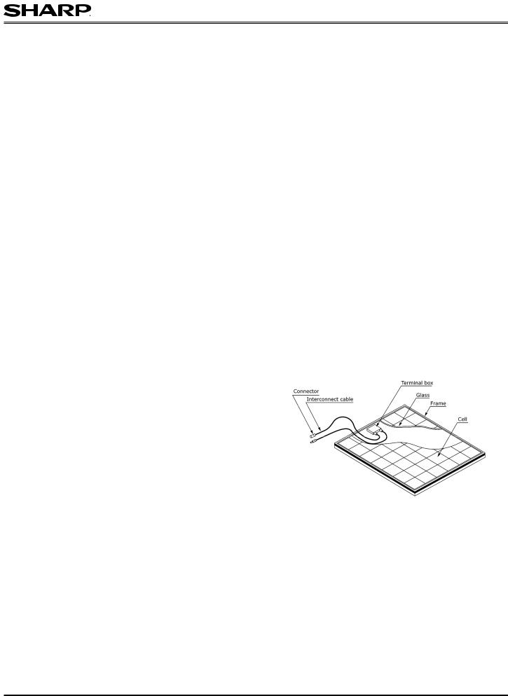
A-3. PV MODULE COMPONENTS
Typical solar module (cutaway view)
A-5. TILT ANGLE SELECTION
The tilt angle of the PV module is measured between the surface of the PV module and a horizontal ground surface. The PV module generates maximum output power when it faces the sun directly.
For standalone systems with batteries where the PV modules are attached to a permanent structure, the tilt angle of the PV modules should be selected to optimize the performance based on seasonal load and sunlight. In general, if the PV output is adequate when irradiance is low (e.g., winter), then the angle chosen should be adequate during the rest of the year. For grid-connected installations where the PV modules are attached to a permanent structure, PV modules should be tilted so that the energy
production from the PV modules will be maximized on an annual basis.
A-6. ELECTRICAL INSTALLATION
To ensure proper system operation and maintain the warranty, be careful to observe the correct cable connection polarity (Figure 1) when connecting the modules to a battery or to other modules. If not connected correctly, the bypass diode(s) could be destroyed. All PV modules must
- 2 - |
Installation Manual for PV Modules |

Ver. 2.0 _ Mar 15, 2010
be grounded by electrical connection of the module frames to ground. Care must be taken to arrange the system ground so that the removal of one module from the circuit will not interrupt the grounding of any of the other modules. For grounding, each PV module has a hole in the frame for either a bolt, nut and washer, a ground lug fastened by bolt or screw, or an appropriate screw (hardware not provided). Installation for wiring shall be in accordance with the NEC and grounding method shall comply with the NEC, article 250 and the relevant instructions below. In a connection of this type, the hardware (such as a star washer) must score the frame surface to make positive electrical contact with the frame. The ground wire must not be smaller than No.12 AWG (insulated for 90˚ C min.) and can be insulated with green colored insulation or insulated with green with yellow stripe(s) insulation. The ground wire should be sized according to the NEC and other applicable codes and standards. Hardware used must be compatible with the mounting structure material to avoid galvanic corrosion.
If modules are installed in a readily accessible location (per NEC) where the circuit is operating in excess of 30 volts, nominal, maximum system voltage for DC or 30 volts for AC circuits, NEC requires installing the additional locking sleeve connector (Multi Contact #PV-SSH4). Note that this sleeve is not included with the module. See Figure 2.
(1) Grounding Using Existing Ground Hole (Figure 3,GBL-4DBT)
1.Place Grounding lug (GBL-4DBT, Ilsco Corporation) onto the frame, making sure that the self-captivating thread-cutting screw straddles the grounding hole.
2.Fasten with a #10-32 self-captivating thread-cutting screw (material; stainless steel) and tooth washer (material; stainless steel). Use of a #10-32 self-captivating thread-cutting screw with tooth washer is recommended. Recommended torque is between 2.3 and 2.8 N·m (20 and 25 in.-lbs).
3.Insert the grounding wire into the lug. The grounding wire can be insulated with green colored insulation or insulated with green with yellow stripe(s) insulation. The conductor grounding wire should be 8 -12 AWG (insulated for 90˚ C min.).
4.Fix the ground wire by tightening the screw. This will terminate the wire.
Please contact Ilsco Corporation about item “GBL-4DBT”.
(2) Grounding Using Existing Ground Hole (Figure 4)
The grounding clip (Solklip, available from Tyco Electronics Corporation, part number 1954381-2) assembly consists of a slider, base and #8-32 screw (Material; stainless steel) and hex nut (material; chromate treatment carbon steel).
1.Place the grounding clip onto the frame, making sure that the screw straddles the grounding hole.
2.Thread the hex nut onto the end of the screw, then using a 3/8" wrench, tighten the nut. Recommended torque is between 2.0 and 2.2 N·m. (17.7 to 19.5 in.-lbs).
3.Insert the grounding wire into the wire slot. Press down on both ends of the wire (the wire slot will cause the wire to form a slight curve). The grounding cables can be insulated with green colored insulation or insulated with green with yellow stripe(s) insulation. The conductor should be 10 -12 AWG (insulated for 90˚ C min.).
4.Manually, or using channel lock pliers, push the slider over the base until it covers the base. This will terminate the wire.
Please contact Tyco Electronics Corporation about item “1954381-2”.
(3) Remark
If, while fastening the GBL-4DBT ground lug with self captivating fasteners, the threads strip, use an alternate grounding hole or use a bolted connection, e.g., the Solklip.
SERIES WIRING (VOLTAGE ADDITIVE)
PARALLEL WIRING (CURRENT ADDITIVE)
Figure 1
Additional locking sleeve |
|
Figure 2 (MC; PV-SSH4) |
Figure 3 (Ilsco, GBL-4DBT) |
Figure 4 (Tyco Electronics Corp. 1954381-2)
A-7. MAINTENANCE
Sharp PV modules are designed for long life and require very little maintenance. If the angle of the PV module is 5 degrees or more, normal rainfall is usually sufficient to keep the module glass surface clean under most weather conditions. If dirt build-up becomes excessive, clean the glass surface only with a soft cloth using water. If cleaning the back of the module is required, take utmost care not to damage the back side materials. In order to ensure proper operation of the system, please check all wiring connections and the condition of the wire insulation periodically.
- 3 - |
Installation Manual for PV Modules |
 Loading...