


PG-M10SU/SE
PG-M10XU/XE
SERVICE MANUAL SERVICE-ANLEITUNG
S90i7PG-M10SU
MODELS MODELLE
DLP PROJECTOR
DLP PROJEKTOR
PG-M10SU/SE PG-M10XU/XE
In the interests of user-safety (Required by safety regulations in some countries) the set should be restored to its original condition and only parts identical to those specified should be used.
Im lnteresse der Benutzersicherheit (erforderliche Sicherheitsregeln in einigen Ländern) muß das Gerät in seinen Originalzustand gebracht werden. Außerdem dürfen für die spezifizierten Bauteile nur identische Teile verwendet werden.
CONTENTS / INHALT
|
Page |
• SPECIFICATIONS .............................................. |
2 |
• NOTE TO SERVICE PERSONNEL .................... |
3 |
• OPERATION MANUAL ...................................... |
4 |
• DISASSEMBLY AND REASSEMBLY ............... |
10 |
• REPLACING THE LAMP .................................. |
15 |
• BLOCK DIAGRAM OF OPTICAL SYSTEM |
|
PRINCIPLE ...................................................... |
16 |
• OPTICAL ADJUSTMENT AND MEASURING .. |
17 |
• SAFETY DEVICE ............................................. |
20 |
• TROUBLE SHOOTING TABLE ........................ |
21 |
• BLOCK DIAGRAM ........................................... |
43 |
• PARTS LIST ..................................................... |
44 |
• PACKING OF THE SET ................................... |
51 |
|
Seite |
• TECHNISCHE DATEN ..................................... |
22 |
• HINWEISE FÜR DAS |
|
WARTUNGSPERSONAL ................................. |
23 |
• BEDIENUNGSANLEITUNG ............................. |
24 |
• ZERLEGUNG UND ZUSAMMENBAU ............. |
30 |
• AUSWECHSELN DER LAMPE ........................ |
35 |
• BLOCKDIAGRAMM FÜR OPTISHES |
|
SYSTEMPRINZIP ............................................ |
36 |
• OPTISCHE EINSTELLUNGEN UND |
|
MESSUNG ....................................................... |
37 |
• SICHERHEITSEINRICHTUNG ........................ |
40 |
• FEHLERSUCHTABELLE ................................. |
41 |
• BLOCKSCHALTBILD ....................................... |
43 |
• ERSATZTEILLISTE .......................................... |
44 |
• VERPACKEN DES GERÄTS ........................... |
51 |
SHARP CORPORATION
1

PG-M10SU/SE
PG-M10XU/XE
Specifications
2

NOTE TO SERVICE
PERSONNEL
12345678901234567890123456789012123456789012345
12345678901234567890123456789012123456789012345
UV-RADIATION PRECAUTION
12345678901234567890123456789012123456789012345
12345678901234567890123456789012123456789012345
The light source, metal halide lamp, in the DLP projector emits small amounts of UV-Radiation.
AVOID DIRECT EYE AND SKIN EXPOSURE.
To ensure safety please adhere to the following:
1.Be sure to wear sun-glasses when servicing the projector with the lamp
turned “on” and the top
enclosure removed.
2. Do not operate the lamp outside of the lamp housing.
3.Do not operate for more than 2 hours with the enclosure removed.
UV-Radiation and Medium Pressure
Lamp Precautions
1.Be sure to disconnect the AC plug when replacing the lamp.
2.Allow one hour for the unit to cool down before servicing.
3.Replace only with same type lamp. Type BQC- PGM10X//-1 rated 85V/130W.
4.The lamp emits small amounts of UV-Radiation, avoid direct-eye contact.
5.The medium pressure lamp involves a risk of explosion. Be sure to follow installation instructions described below and handle the lamp with care.
PG-M10SU/SE
PG-M10XU/XE
2345678901234567890123456789012123456789012345
1234567890123456789012345678901212345678901234 5
UV-RADIATION PRECAUTION (Continued)
234567890123456789012345678901212345678901234
1234567890123456789012345678901212345678901234

 Lamp Replacement
Note:
Since the lamp reaches a very high temperature during units operation replacement of the lamp should be done at least one hour after the power has been turned off. (to allow the lamp to cool off.) Installing the new lamp, make sure not to touch the
lamp (bulb) replace the lamp by holding its reflector
2.
[Use original replacement only.]
1 Lamp
2 Reflector
DANGER ! –– Never turn the power on without the lamp to avoid electric-shock or damage of the devices since the stabilizer generates high voltages at its start.
Since small amounts of UV-Radiation are emitted from an opening between the duct cover and the lamp housing, it is recommended to place the LENS CAP on the opening during servicing to avoid eye and skin exposure (Fig. 1).
Notes:
»Please obtain a lens cap before servicing a model PG-M10SU/SE, PG-M10XU/XE that is received without one.
»The color wheel is running at high speed. Do not touch it nor bring anything nearby.
COLOR WHEEL |
LENS CAP |
Figure 1.
3

PG-M10SU/SE
PG-M10XU/XE
Location of Controls
4

PG-M10SU/SE PG-M10XU/XE
5

PG-M10SU/SE
PG-M10XU/XE
Reomte Control
6

PG-M10SU/SE
PG-M10XU/XE
Connections
7

PG-M10SU/SE PG-M10XU/XE
8

PG-M10SU/SE
PG-M10XU/XE
Pin Assignments
Dimensions
9
PG-M10SU/SE
PG-M10XU/XE
DISASSEMBLY AND REASSEMBLY
1. Preparations and precautions
●Tools required
1.Phillips screwdriver, Nos. 1 and 2
2.Phillips and bladed precision screwdrivers
3.Anti-static wrist band
4.Hexagonal wrench (opposite side: ___ mm)
●Precautions for disassembly and reassembly
1.Before starting the procedure, unplug the power cable.
2.Some parts are still hot immediately after operation. Wait until they have cooled down.
3.Restore the components, screws and wires in their original positions.
4.Follow the important notes in handling the components and carrying out the job.
5.Be careful not to confuse the specific component parts for different models.
6.Do not tamper with the unit to ensure safety.
2.Disassembly and reassembly
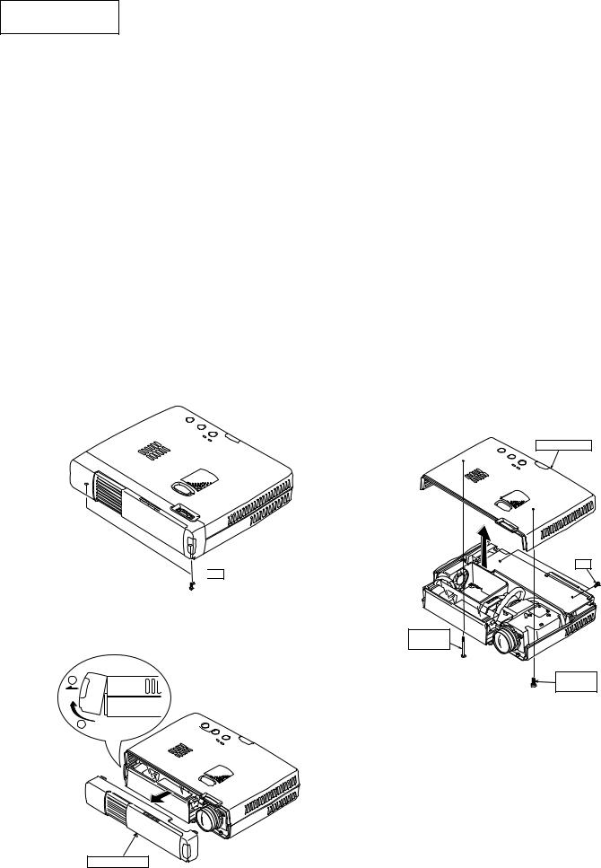
1)Front panel (See Fig. 1 and Fig. 1-A.) Remove the two screws (S-8) shown in Fig. 1. Remove the front panel as shown in Fig. 1-A. Note: Take care not to damage the IR cable.
 S-8
S-8
Fig. 1
2
1
2)Top cover (See Fig. 2.)
Remove the two louver screws (S-8) shown in Fig. 2.
Remove the top cover as shown in Fig. 2.
Note: Take care not to damage the speaker cable.
Top Cover
S-8
Louver
Screw
Louver
Screw
Fig. 2
Front Panel
Fig. 1-A
10
 Loading...