


PC935
Sharp PC935, PC930, PC931, PC932, PC933 Datasheet
...
PC930 Series
■ Model Line-up
■ Features
■ Applications
*1 Pulse width<=100 µs
*3 For 10 seconds
(
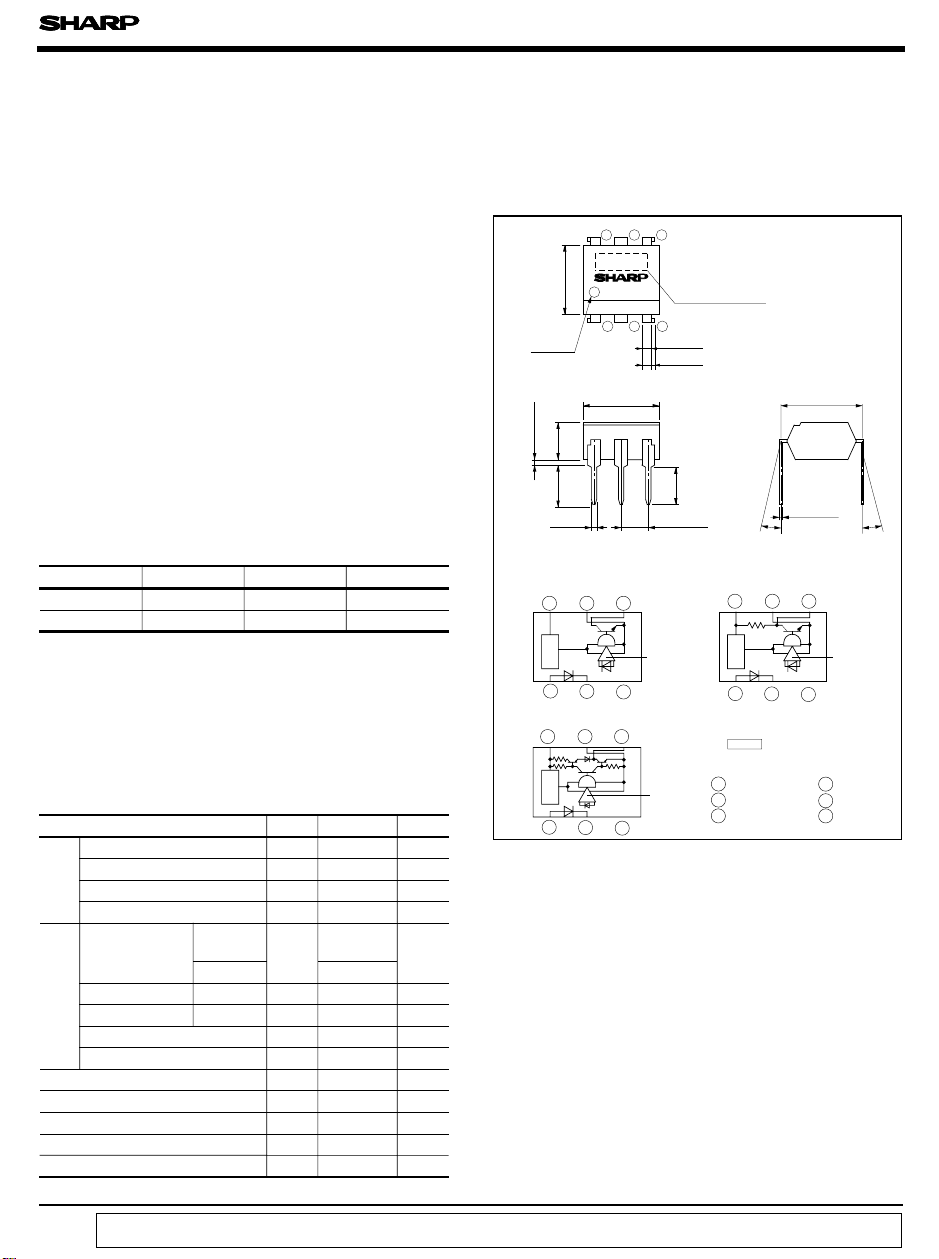
Unit : mm
)
mark
θ
Anode
θ
Model No.
PC930/PC931 PC932/PC933
PC934/PC935
Internal connection diagram
Voltage
regulator
••••••
Digital Output, High Sensitivity
Type OPIC Photocoupler
■ Outline Dimensions
Duty ratio : 0.001
■ Absolute Maximum Ratings
Parameter
Symbol
Rating Unit
Input
Forward current I
F
20 mA
*1
Peak forward current I
FM
1A
Reverse voltage V
R
6V
Power dissipation P 70 mW
Output
Supply voltage
PC930/PC931
PC932/PC933
V
CC
- 0.5 to 16.0
V
PC934/PC935
- 0.5 to 7.0
High level output voltage
PC930/PC931
V
OH
- 0.5 to 16.0
V
High level output current
PC934/PC935
I
OH
- 800 µA
Low level output current
I
OL
50 mA
P
O
150 mW
Total power dissipation
P
tot
170 mW
*2
Isolation voltage V
iso
V
rms
Operating temperature
T
opr
- 25 to + 85
˚C
Storage temperature
*3
Soldering temperature
T
stg
- 40 to + 125
˚C
T
sol
260 ˚C
1. High sensitivity
(
I
FLH
, I
FHL
: MAX. 1mA
)
2. TTL and LSTTL compatible output
3. Operating supply voltage range
4. Various output forms
(
Open collector output, pull-up resistor
built-in type, totem pole output
)
5. Low output current dissipation
(
I
CCL
: MAX. 3.8mA
)
1. Computer terminals
2. High speed line receivers
3. Interfaces with various data transmission
equipment
Power dissipation
PC930 Series
data books, etc. Contact SHARP in order to obtain the latest version of the device specification sheets before using any SHARP's device.”
“ In the absence of confirmation by device specification sheets, SHARP takes no responsibility for any defects that occur in equipment using any of SHARP's devices, shown in catalogs,
123
456
0.5 TYP
Amp
123
456
1 Anode
2 Cathode
3 NC
5 GND
Amp
Amp
(
V
CC
: 4.5 to 15V, PC930/PC931/PC932/PC933
)
Open collector
output type
Pull-up resistor
built-in type
Totem pole
output type
Low active PC930 PC932 PC934
High active PC931 PC933 PC935
An OPIC consists of a light-detecting element and signal-
processing circuit integrated onto a single chip.
* “OPIC ”
(
Optical IC
)
is a trademark of the SHARP Corporation.
6. High isolation voltage between input and
0.9
± 0.2
1.2
±0.3
AC for 1 minute
*2 40 to 60%RH,
5 000
7. Recognized by UL, file No. E64380
output
(
V
iso
: 5 000V
rms
)
θ = 0 to 13 ˚
6.5
± 0.5
7.12
± 0.5
3.5
± 0.5
3.7
± 0.5
0.5
± 0.1
2.54
± 0.25
3.35
± 0.5
0.26
± 0.1
7.62
± 0.3
4 V
O
6 V
CC
123
456
456
123
PC930 Series
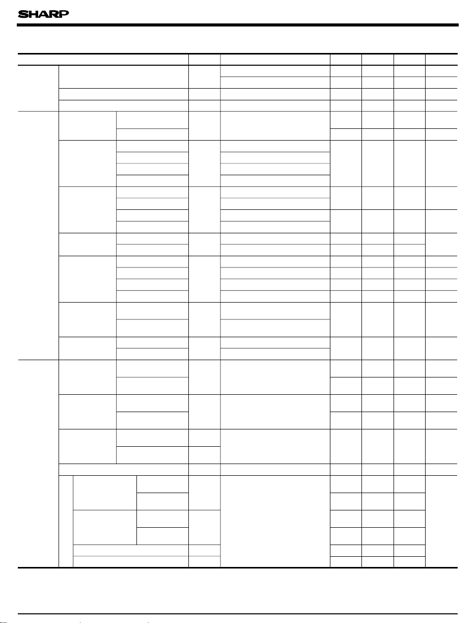
Symbol Conditions
V
F
I
F
= 2mA
I
F
= 0.1mA
Reverse current I
R
Ta= 25˚C, V
R
=3V
Terminal capacitance C
t
Ta= 25˚C, V= 0, f= 1kHz
Output
PC930/PC931
PC932/PC933
V
CC
PC934/PC935
PC930/PC932
V
OL
I
OL
= 16mA, V
CC
= 5V, I
F
= 1mA
PC931/PC933
I
OL
= 16mA, V
CC
= 5V, I
F
=0
PC934
I
OL
= 16mA, V
CC
= 4.5V, I
F
= 1mA
PC935
I
OL
= 16mA, V
CC
= 4.5V, I
F
=0
PC932
V
OH
V
CC
= 5V, I
F
=0
PC933 V
CC
= 5V, I
F
= 1mA
V
CC
= 4.5V, I
F
= 0, I
OH
= - 400
µ
A
PC934
PC935
V
CC
= 4.5V, I
F
= 1mA, I
OH
= - 400 µ A
PC930
I
OH
V
CC
=V
O
= 15V, I
F
=0
V
CC
=V
O
= 15V, I
F
= 1mAPC931
PC930
I
CCL
V
CC
= 5V, I
F
= 1mA
V
CC
= 5V, I
F
=0PC931
V
CC
= 5V, I
F
= 1mA
V
CC
= 5V, I
F
=0
I
CCH
V
CC
= 5V, I
F
=0
V
CC
= 5V, I
F
= 1mA
I
OS
V
CC
= 5V, I
F
= 0, T= Within 1 second
V
CC
= 5V, I
F
= 1mA, T= Within 1 second
Transfer
charac-
teristics
I
FHL
V
CC
= 5V, R
L
= 280Ω
I
FLH
V
CC
= 5V, R
L
= 280Ω
I
FLH
/I
FHL
V
CC
= 5V, R
L
= 280Ω
I
FHL
/I
FLH
R
ISO
t
PHL
Ta= 25˚C
V
CC
=5V
I
F
= 1mA
R
L
= 280Ω
Fig.1
t
PLH
Fall time
Response time
t
f
Rise time t
r
PC932/PC934
PC933/PC935
PC934
PC935
PC930/PC932
PC934
PC931/PC933
PC935
PC930/PC932
PC934
PC931/PC933
PC935
PC930/PC932
PC934
PC931/PC933
PC930/PC932
PC934
PC931/PC933
PC935
PC935
Isolation resistance
propagation
delay time
“ High→Low”
“ Low→High”
propagation
delay time
Operating
supply
voltage
Low level
output
voltage
Low level
supply
current
High level
supply
current
Output short
circuit current
■■ Electro-optical Characteristics
Low” Thre-
shold input
current
High” Thre-
shold input
current
Parameter
Input
Forward voltage
*4 I
FHL
represents forward current when output goes from high to low.
*5 I
FLH
represents forward current when output goes from low to high.
*6 Hysteresis stands for I
FLH
/I
FHL
.
*4
“ High→
*5
“ Low→
*6
Hysteresis
MIN. TYP. MAX. Unit
- 1.1 1.4 V
0.55 0.95 - V
--10µA
- 30 250 pF
4.5 - 15 V
4.5 5.5 V
- 0.15 0.4 V
3.5 - - V
2.4 - - V
- - 100
µA
- - 100
- 1.3 3.4 mA
- 1.3 3.4 mA
- 1.7 3.8 mA
- 1.7 3.8 mA
- 0.7 2.2 mA
61735mA
- 0.5 1.0 mA
0.1 0.4 - mA
0.1 0.4 - mA
- 0.5 1.0 mA
- 0.8 - -
5x10
10
10
11
- Ω
39
µs
-
-
515
-515
-39
- 0.05 0.5
- 0.1 0.5
(
Ta= 0 to + 70˚C unless otherwise specified.
)
High level
output
voltage
High level
output
current
PC930/PC932
PC934
PC931/PC933
PC935
PC930/PC932
PC934
PC931/PC933
PC935
Ta = 25˚C, DC500V, 40 to 60% RH
-
 Loading...