


PG-M15X
PG-M15S
AN-M15T


 SERVICE MANUAL SERVICE-ANLEITUNG
S91A5PG-M15S/
DIGITAL MULTIMEDIA PROJECTOR
DIGITALER MULTIMEDIA PROJEKTOR
MODELS MODELLE
PG-M15X PG-M15S
AN-M15T
In the interests of user-safety (Required by safety regulations in some countries) the set should be restored to its original condition and only parts identical to those specified should be used.
Im lnteresse der Benutzersicherheit (erforderliche Sicherheitsregeln in einigen Ländern) muß das Gerät in seinen Originalzustand gebracht werden. Außerdem dürfen für die spezifizierten Bauteile nur identische Teile verwendet werden.
This document has been published to be used for SHARP CORPORATION after sales service only.
The contents are subject to change without notice.
1

PG-M15X
PG-M15S
AN-M15T
CONTENTS
|
Page |
» SPECIFICATIONS ............................................. |
3 |
» IMPORTANT SERVICE SAFETY |
|
NOTES (for USA) ............................................... |
4 |
» NOTE TO SERVICE PERSONNEL ................... |
5 |
» OPERATION MANUAL ...................................... |
8 |
» REMOVING OF MAJOR PARTS ..................... |
13 |
» RESETTING THE TOTAL LAMP TIMER ......... |
23 |
» OPTICAL ADJUSTMENT AND MEASURING ... |
25 |
» THE OPTICAL UNIT OUTLINE ....................... |
28 |
» TROUBLE SHOOTING TABLE ........................ |
30 |
» OVERALL WIRING DIAGRAM ........................ |
70 |
|
Page |
» BLOCK DIAGRAM ........................................... |
71 |
» SCHEMATIC DIAGRAM .................................. |
74 |
» PRINTED WIRING BOARD ASSEMBLIES ..... |
99 |
» PARTS LIST |
|
Ë ELECTRICAL PARTS ................................ |
101 |
Ë CABINET AND MECHANICAL PARTS ..... |
108 |
Ë ACCESSORIES PARTS ............................ |
112 |
Ë PACKING PARTS ....................................... |
112 |
» PACKING OF THE SET ................................. |
113 |
» AN-M15T ........................................................ |
114 |
INHALT
|
Seite |
» TECHNISCHE DATEN ..................................... |
38 |
» HINWEISE FÜR DAS |
|
WARTUNGSPERSONAL ................................ |
39 |
» BEDIENUNGSANLEITUNG ............................ |
40 |
» ENTFERNEN DER HAUPTTEILE .................. |
45 |
» RÜCKSTELLEN DES |
|
LAMPENBETRIEBSZEIT-TIMERS ................. |
55 |
» OPTISCHE EINSTELLUNG UND |
|
MESSUNG ...................................................... |
57 |
» ÜBERSICHT DER OPTIK-EINHEIT ............... |
60 |
» FEHLERSUCHTABELLE ................................ |
62 |
» GESAMTSCHALTPLAN ................................. |
70 |
|
Seite |
» BLOCKSCHALTBILD ...................................... |
71 |
» SCHEMATISCHER SCHALTPLAN ................. |
74 |
» LEITERPLATTENEINHEITEN ........................ |
99 |
» ERSATZTEILLISTE |
|
Ë ELEKTRISCHE BAUTEILE ....................... |
101 |
Ë GEHÄUSE UND MECHANISCHE |
|
BAUTEILE .................................................. |
108 |
Ë ZUBEHÖRTEILE ....................................... |
112 |
Ë VERPACKUNGSTEILE .............................. |
112 |
» VERPACKEN DES GERÄTS ......................... |
113 |
» AN-M15T ........................................................ |
114 |
2

PG-M15X
PG-M15S
AN-M15T
Specifications
Product type |
Digital Multimedia Projector |
|
Model |
PG-M15X/PG-M15S |
|
Video system |
NTSC/NTSC 4.43/PAL/PAL-M/PAL-N/PAL 60/SECAM/DTV480i |
|
Display method |
Single Chip Digital Micromirror Device™ (DMD™) by Texas Instruments |
|
DMD panel |
Panel size: 0.7 (17.8 mm), 1 chip XGA DMD/SVGA DMD |
|
|
No. of dots: 786,432 dots (1,024 [H] 768 [V])/PG-M15X |
|
|
480,000 dots (800 [H] 600 [V])/PG-M15S |
|
Lens |
1-1.2 X zoom lens, F2.2–2.4, f 28.5–34.2 mm |
|
Projection lamp |
High Intensity Discharge Lamp (HID Lamp), AC 130 W |
|
Contrast ratio |
500:1 |
|
Video input signal |
RCA Connector (INPUT 3): VIDEO, composite video, 1.0 Vp-p, sync negative, 75 Ω |
|
|
terminated |
|
S-video input signal |
4-pin Mini DIN connector (INPUT 2) |
|
|
Y (luminance signal): 1.0 Vp-p, sync negative, 75 Ω terminated |
|
|
C (chrominance signal): Burst 0.286 Vp-p, 75 Ω terminated |
|
Component input signal |
29-pin Connector (INPUT 1) |
|
|
Y: 1.0 Vp-p, sync negative, 75 Ω terminated |
|
|
PB: 0.7 Vp-p, 75 Ω |
terminated |
Horizontal resolution |
PR: 0.7 Vp-p, 75 Ω |
terminated |
580 TV lines (video input) |
||
Computer RGB input signal |
29-pin CONNECTOR (INPUT 1) |
|
|
RGB separate/sync on green type analog input: 0–0.7 Vp-p, positive, 75 Ω terminated |
|
|
HORIZONTAL SYNC. SIGNAL: TTL level (positive/negative) |
|
Pixel clock |
VERTICAL SYNC. SIGNAL: Same as above |
|
25–135 MHz |
|
|
Vertical frequency |
56–85 Hz |
|
Horizontal frequency |
31.5–80 kHz |
|
Audio input signal |
3.5 ø MINIJACK: AUDIO, 0.4 Vrms, more than 47 kΩ (stereo) |
|
Audio output |
2.0 W (monaural) |
|
Speaker system |
4 2.8 cm |
|
Rated voltage |
AC 100–240 V |
|
Input current |
2.0 A |
|
Rated frequency |
50/60 Hz |
|
Power consumption |
180 W |
|
Power dissipation |
<680 BTU/hour |
|
Operating temperature |
41°F to 95°F ( 5°C to 35°C) |
|
Storage temperature |
4°F to 140°F ( 20°C to 60°C) |
|
Cabinet |
Magnesium alloy (Terminal panel, Lamp cover and Side vent cover constructed of plastic) |
|
I/R carrier frequency |
38 kHz |
|
Dimensions (approx.) |
8 55⁄64 1 31⁄32 6 59⁄64 (225 (W) 50 (H) 176 (D) mm) (main body only) |
|
|
8 55⁄64 2 19⁄32 6 31⁄32 (225 (W) 66 (H) 177 (D) mm) (including adjustment feet |
|
Weight (approx.) |
and projecting parts) |
|
3.5 lbs (1.6 kg) |
|
|
Supplied accessories |
Remote control, Two AAA size batteries, Power cord for U.S., Canada etc. (5 11 , 1.8 m), |
|
|
Power cord for Europe, except U.K. (5 11 , 1.8 m), Power cord for U.K., Hong Kong and |
|
|
Singapore (5 11 , 1.8 m), Power cord for Australia, New Zealand and Oceania (5 11 , 1.8 |
|
|
m), DVI-Analog to VGA cable (5 11 , 1.8 m), DVI-Analog to VGA adaptor, PC audio cable |
|
|
(6 7 , 2.0 m), DIN-D-sub RS-232C cable (6 1/2 , 16.5 cm), Computer RGB cable (5 11 , |
|
|
1.8 cm), USB mouse control cable (5 11 , 1.8 m), Video cable (5 11 , 1.8 m), S-video |
|
|
cable (5 11 , 1.8 m), AV audio cable (5 11 , 1.8 m), Soft carrying pouch, Lenscap with |
|
Replacement parts |
strap, CD-ROM, Projector operation manual, Projector quick reference guide |
|
Remote control (9HJ7583104001), AAA size battery (9HJ4683101001), Power cord for |
||
|
U.S., Canada etc. (9HJ4283114001), Power cord for Europe, except U.K. |
|
|
(9HJ4283116001), Power cord for U.K., Hong Kong and Singapore (9HJ4283117001), |
|
|
Power cord for Australia, New Zealand and Oceania (9HJ4283118001), DVI-Analog to |
|
|
VGA cable (9HJ4283119001), DVI-Analog to VGA adaptor (9HJ4283124001), PC audio |
|
cable (9HJ4283120001), DIN-D-sub RS-232C cable (9HJ4283123001), Computer RGB cable (9HJ4283111001), USB mouse control cable (9HJ4283122001), Video cable (9HJ4283112001), S-video cable (9HJ4283113001), AV audio cable (9HJ4283121001), Soft carrying pouch (9HJ5383101001), Lens cap with strap (9HJ7083117001), CD-ROM (9HJ3683104001), Projector operation manual (9HJ3683107001), Projector quick reference guide (9HJ3683110001)
This SHARP projector uses a DMD panel. This very sophisticated panel contains 786,432 (PG-M15X)/480,000 (PG-M15S) pixels. As with any high technology electronic equipment such as large screen TVs, video systems and video cameras, there are certain acceptable tolerances that the equipment must conform to.
This unit has some inactive pixels within acceptable tolerances which may result in inactive dots on the picture screen. This will not affect the picture quality or the life expectancy of the unit.
Specifications are subject to change without notice.
3

PG-M15X
PG-M15S
AN-M15T
IMPORTANT SERVICE SAFETY NOTES (for USA)
ËService work should be performed only by qualified service technicians who are thoroughly familiar with all safety checks and servicing guidelines as follows:
WARNING
1.For continued safety, no modification of any circuit should be attempted.
2.Disconnect AC power before servicing.
BEFORE RETURNING THE PROJECTOR:
(Fire & Shock Hazard)
Before returning the projector to the user, perform the following safety checks:
1.Inspect lead wires are not pinched between the chassis and other metal parts of the projector.
2.Inspect all protective devices such as non-metallic control knobs, insulating materials, cabinet backs, adjustment and compartment covers or shields, isolation resistor-capacity networks, mechanical insulators, etc.
3.To be sure that no shock hazard exists, check for current leakage in the following manner:
»Plug the AC cord directly into a 120-volt AC outlet, (Do not use an isolation transformer for this test).
»Using two clip leads, connect a 1.5k ohm, 10 watt resistor paralleled by a 0.15µF capacitor in parallel between all exposed metal cabinet parts and earth ground.
»Use an AC voltmeter with sensitivity of 5000 ohm per volt., or higher, sensitivity to measure the AC voltage drop across the resistor (See Diagram).
»All checks must be repeated with the AC plug connection reversed. (If necessary, a non-polarized adapter plug must be used only for the purpose of completing these checks.)
Any reading of 0.3 volts RMS (this corresponds to 0.2 milliamp. AC.) or more is excessive and indicates a potential shock hazard which must be corrected before returning the unit to the owner.
AC |
VOLTMETER |
1.5k ohm (10W) |
|
0.15 F |
TEST PROBE |
|
TO EXPOSED |
CONNECT TO KNOWN |
METAL PARTS |
EARTH GROUND |
12345678901234567890123456789012123456789012345678901234567890121234567890123456789012345678901212
1234567890123456789012345678901212345678901234567890123456789012123456789012345678901234567890121 2
12345678901234567890123456789012123456789012345678901234567890121234567890123456789012345678901212
SAFETY NOTICE
Many electrical and mechanical parts in Projector have special safety-related characteristics.
These characteristics are often not evident from visual inspection, nor can protection afforded by them be necessarily increased by using replacement components rated for higher voltage, wattage, etc.
Replacement parts which have these special safety characteristics are identified in this manual; electrical components having such features are identified by “å” and shaded areas in the Replacement Parts Lists and Schematic Diagrams. For continued protection, replacement parts must be identical to those used in the original circuit. The use of a substitute replacement parts which do not have the same safety characteristics as the factory recommended replacement parts shown in this service manual, may create shock, fire or other hazards.
WARNING: The bimetallic component has the primary conductive side exposed. Be very careful in handling this component when the power is on.
AVIS POUR LA SECURITE
De nombreuses pièces, électriques et mécaniques, dans les projecteur à présentent des caractéristiques spéciales relatives à la sécurité, qui ne sont souvent pas évidentes à vue.
Le degré de protection ne peut pas être nécessairement augmentée en utilisant des pièces de remplacement étalonnées pour haute tension, puissance, etc.
Les pièces de remplacement qui présentent ces caractéristiques sont identifiées dans ce manuel; les pièces électriques qui présentent ces particularités sont identifiées par la marque “å” et hachurées dans la liste des pièces de remplacement et les diagrammes schématiques. Pour assurer la protection, ces pièces doivent être identiques à celles utilisées dans le circuit d’origine. L’utilisation de pièces qui n’ont pas les mêmes caractéristiques que les pièces recommandées par l’usine, indiquées dans ce manuel, peut provoquer des électrocutions, incendies ou autres accidents.
AVERTISSEMENT: La composante bimétallique dispose du conducteur primaire dénudé. Faire attention lors de la manipulation de cette composante sous tension.
1234567890123456789012345678901212345678901234567890123456789012123456789012345678901234567890121 2
12345678901234567890123456789012123456789012345678901234567890121234567890123456789012345678901212
4

NOTE TO SERVICE
PERSONNEL
12345678901234567890123456789012123456789012345
12345678901234567890123456789012123456789012345
UV-RADIATION PRECAUTION
12345678901234567890123456789012123456789012345
12345678901234567890123456789012123456789012345
The light source, metal halide lamp, in the projector emits small amounts of UV-Radiation.
AVOID DIRECT EYE AND SKIN EXPOSURE.
To ensure safety please adhere to the following:
1.Be sure to wear sun-glasses when servicing the projector with the lamp
turned “on” and the top
enclosure removed.
2. Do not operate the lamp outside of the lamp housing.
3.Do not operate for more than 2 hours with the enclosure removed.
PG-M15X
PG-M15S
AN-M15T
NOTE POUR LE PERSONNEL D’ENTRETIEN
2345678901234567890123456789012123456789012345
2345678901234567890123456789012123456789012345
PRECAUTION POUR LES RADIATIONS UV
2345678901234567890123456789012123456789012345
2345678901234567890123456789012123456789012345
La source de lumière, la lampe métal halide, dans le projecteur émet de petites quantités de radiation UV.
EVITEZ TOUTE EXPOSITION DIRECTE DES YEUX ET DE LA PEAU.
Pour votre sécurité, nous vous prions de respecter les points suivants:
1.Toujours porter des lunettes de soleil lors d’un entretien du projecteur
avec la lampe allumée
et le haut du coffret retiré.
2.Ne pas faire fonctionner la lampe à l’extérieur du boîtier de lampe.
3.Ne pas faire fonctionner plus de 2 heures avec le coffret retiré.
UV-Radiation and Medium Pressure
Lamp Precautions
1.Be sure to disconnect the AC plug when replacing the lamp.
2.Allow one hour for the unit to cool down before servicing.
3.Replace only with same type lamp. Type 9HJ7083119001 or BQC-PGM15X//1 rated 85V/ 130W.
4.The lamp emits small amounts of UV-Radiation, avoid direct-eye contact.
5.The medium pressure lamp involves a risk of explosion. Be sure to follow installation instructions described below and handle the lamp with care.
Précautions pour les radiations UV et la lampe moyenne pression
1.Toujours débrancher la fiche AC lors du remplacement de la lampe.
2.Laisser l’unité refroidir pendant une heure avant de procéder à l’entretien.
3.Ne remplacer qu’avec une lampe du même type. Type 9HJ7083119001 ou BQC-PGM15X//1 caractéristique 85V/130W.
4.La lampe émet de petites quantités de radiation UVéviter tout contact direct avec les yeux.
5.La lampe moyenne pression implique un risque d’explosion. Toujours suivre les instructions d’installation décrites ci-dessous et manipuler la lampe avec soin.
5

PG-M15X
PG-M15S
AN-M15T
12345678901234567890123456789012123456789012345
12345678901234567890123456789012123456789012345
UV-RADIATION PRECAUTION (Continued)
123456789012345678901234567890121234567890123 4
1234567890123456789012345678901212345678901234

 Lamp Replacement
Note:
Since the lamp reaches a very high temperature during units operation replacement of the lamp should be done at least one hour after the power has been turned off. (to allow the lamp to cool off.) Installing the new lamp, make sure not to touch the
lamp (bulb) replace the lamp by holding its reflector
2.
[Use original replacement only.]
1 Lamp
2 Reflector
2345678901234567890123456789012123456789012345
2345678901234567890123456789012123456789012345
PRECAUTION POUR LES RADIATIONS UV (Suite)
234567890123456789012345678901212345678901234 5
2345678901234567890123456789012123456789012345

 Remplacement de la lampe
Remarque:
Comme la lampe devient très chaude pendant le fonctionnement de l’unité, son remplacement ne doit être effectué au moins une heure après avoir coupé l’alimentation (pour permettre à la lampe de refroidir). En installant la nouvelle lampe, s’assurer de ne pas toucher la lampe (ampoule). Remplacer la lampe en tenant son réflecteur 2.
[N’utiliser qu’un remplacement d’origine.]
1 Lampe
2 Reflecteur
DANGER ! –– Never turn the power on without the lamp to avoid electric-shock or damage of the devices since the stabilizer generates high voltages at its start.
Since small amounts of UV-Radiation are emitted from an opening between the duct cover and the lamp housing, it is recommended to place the LENS CAP on the opening during servicing to avoid eye and skin exposure (Fig. 1).
Note: Please obtain a lens cap before servicing a models PG-M15X/M15S that is received without one.
LENS CAP
Figure 1.
DANGER ! –– Ne jamais mettre sous tension sans la lampe pour éviter un choc électrique ou des dommages des appareils car le stabilisateur génère de hautes tensions à sa mise en route.
Comme de petites quantités de radiation UV sont émises par une ouverture entre le couvercle du conduit et le botier de la lampe,il est recommandé de placer le CAPUCHON D'OPTIQUE sur l'ouverture pendant l'entretien pouréviter une exposition des yeux et la peau (Fig. 1).
Remarque: Priére de se procurer un capuchon d'optique acant d'entretien un modéle PG-M15X/M15S qui est livré sans.
CAPUCHON D'OPTIQUE
Figure 1.
6

PG-M15X
PG-M15S
AN-M15T
WARNING: High brightness light source, do not stare into the beam of light, or view directly. Be especially careful that children do not stare directly in to the beam of light.
WARNING: TO REDUCE THE RISK OF FIRE OR ELECTRIC SHOCK, DO NOT EXPOSE THIS UNIT TO MOISTURE OR WET LOCATIONS.
CAUTION |
RISK OF ELECTRIC SHOCK. |
DO NOT REMOVE SCREWS |
EXCEPT SPECIFIED USER |
SERVICE SCREWS |
CAUTION: TO REDUCE THE RISK OF ELECTRIC SHOCK, |
DO NOT REMOVE CABINET. |
NO USER-SERVICEABLE PARTS EXCEPT LAMP UNIT. |
REFER SERVICING TO QUALIFIED SERVICE |
PERSONNEL. |
The lighting flash with arrowhead within a triangle is intended to tell the user that parts inside the product are risk of electric shock to persons.
The exclamation point within a triangle is intended to tell the user that important operating and servicing instructions are in the manual with the projector.
12345678901234567890123456789012123456789012345678901234567890121234567890123456789012345678901212
12345678901234567890123456789012123456789012345678901234567890121234567890123456789012345678901212
AVERTISSEMENT: Source lumineuse de grande intensité. Ne pas fixer le faisceau lumineux ou le regarder directement. Veiller particulièrement à éviter que les enfants ne fixent directement le faisceau lumineux.
AVERTISSEMENT: AFIN D’EVITER TOUT RISQUE D’INCENDIE OU D’ELECTROCUTION, NE PAS PLACER CET APPAREIL DANS UN ENDROIT HUMIDE OU MOUILLE.
ATTENTION
RISQUE
D’ELECTROCUTION NE
PASRETIRER LES VIS, A
L’EXCEPTION DES VIS DE
REPARATION UTILISATEUR
SPECIFIEES
ATTENTION: POUR EVITER TOUT RISQUE
D’ELECTROCUTION, NE PAS RETIRER LE CAPOT. AUCUNE DES PIECES INTERIEURES N’EST REPARABLE
PAR L’UTILISATEUR, A L’EXCEPTION DE L’UNITE DE
LAMPE. POUR TOUTE REPARATION, S’ADRESSER A UN
TECHNICIEN D’ENTRETIEN QUALIFIE.
L’éclair terminé d’une flèche à l’intérieur d’un triangle indique à l’utilisateur que les pi‘eces se trouvant dans l’appareil sont susceptibles de provoquer une décharge électrique.
Le point d’exclamation à l’intérieur d’un triangle indique à l’utilisateur que les instructions de fonctionnement et d’entretien sont dé taillé es dans les documents fournis avec le projecteur.
7
PG-M15X
PG-M15S
AN-M15T
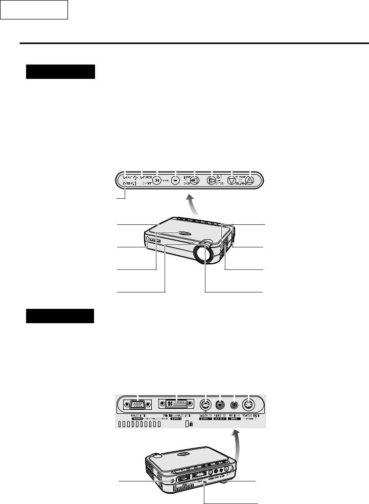
Location of Controls
Projector
Front and Top View
MENU button |
|
|
|
|
|
|
|
|
|
|
INPUT/BACK button |
||
|
|
|
|
|
|
|
|
|
|||||
ON/OFF button |
|
|
|
|
|
|
|
|
|
|
AUTO SYNC/ENTER button |
||
|
|
|
|
|
|
|
|||||||
POWER indicator |
|
|
|
|
|
|
|
|
|
|
|
|
KEYSTONE(+ / – )/ |
|
|
|
|
|
|
|
|
|
|
SELECT/ADJUST('/") buttons |
|||
|
|
|
|
|
|
|
|
|
|
|
|
|
|
LAMP REPLACEMENT |
|
|
|
|
|
|
|
|
|
|
|
|
|
indicator |
|
|
|
|
|
|
|
|
|
|
|
||
|
|
|
|
|
|
|
|
|
|
|
|
|
|
|
|
|
|
|
|
|
|
|
|
|
|
|
|
TEMPERATURE WARNING
indicator |
|
Cooling fan (Exhaust vent) |
Intake vent |
Remote control sensor |
AC socket |
HEIGHT ADJUST button |
Speaker |
FOCUS ring |
ZOOM knob |
Side and Rear View
S-VIDEO INPUT 2 terminal |
|
|
|
|
VIDEO INPUT 3 terminal |
|||||||||
(4-pin Mini DIN) |
|
|
|
|
|
|
|
|
|
(RCA) |
||||
DVI-DIGITAL/ANALOG |
|
|
|
|
|
|
|
AUDIO INPUT terminal |
||||||
INPUT 1 port (29-pin) |
|
|
|
|
|
|
|
|
|
|
(3.5 mm stereo Minijack) |
|||
ANALOG OUTPUT port for |
|
|
|
|
|
|
|
|
RS-232C/MOUSE port |
|||||
INPUT 1 (HD 15) |
|
|
|
|
|
|
|
|
|
|
(7-pin Mini DIN) |
|||
|
|
|
|
|
|
|
|
|
|
|
|
|
|
|
|
|
|
|
|
|
|
|
|
|
|
|
|
|
|
|
|
|
|
|
|
|
|
|
|
|
|
|
|
|
Remote control sensor |
Adjuster |
Kensington Security Standard connector
8
PG-M15X
PG-M15S
AN-M15T
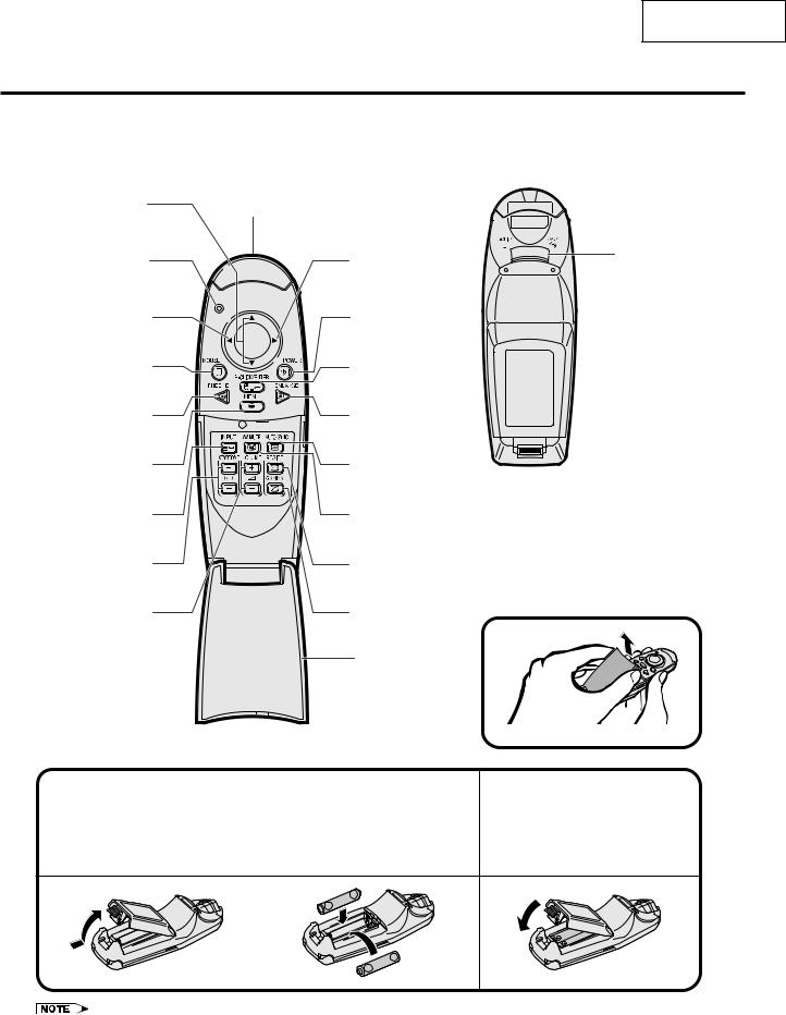
Operating the Wireless Mouse Remote Control
Remote Control
Front View |
|
Rear View |
|
|
|
Mouse ('/")/ |
Remote control signal |
Adjustment ('/") |
transmitting window |
buttons |
|
Remote control signal |
|
transmitter indicator |
|
(Flashes when remote |
|
control sends a signal) |
|
Mouse (\) button |
|
MOUSE button |
|
FREEZE button |
|
MENU button |
|
INPUT button |
|
KEYSTONE( + / – ) |
|
buttons |
|
VOLUME buttons |
|
Inserting the Batteries
Mouse ( |) button |
LEFT-CLICK/ |
BACK button |
POWER button
RIGHT-CLICK/
ENTER button
ENLARGE button
AUTO SYNC button
AV MUTE button
RESIZE button
Opening the Flip Cover
GAMMA button
Flip cover
Press the tab and lift open |
Insert two AAA size |
||||||||||
1 the battery cover in the |
2 batteries, making sure |
||||||||||
direction of the arrow. |
their polarities match the |
||||||||||
|
+ and – marks inside |
||||||||||
|
the battery compartment. |
||||||||||
|
|
|
|
|
|
|
|
|
|
|
|
|
|
|
|
|
|
|
|
|
|
|
|
|
|
|
|
|
|
|
|
|
|
|
|
|
|
|
|
|
|
|
|
|
|
|
|
|
|
|
|
|
|
|
|
|
|
|
|
3 Insert the tabs on the end of the battery cover into their slots and press the cover into position.
•If the remote control gets wet, wipe it dry immediately.
•Avoid excessive heat and humidity.
•If you will not be using the remote control for a long time, remove the batteries.
•Do not mix new and old or different types of batteries.
•There are operations that can only be carried out by remote control. Handle the remote control carefully.
9

PG-M15X
PG-M15S
AN-M15T
Connection Pin Assignments
DVI INPUT 1 Port: 29-pin
C5 |
|
|
|
C4 |
C3 24 |
17 |
9 |
16 8 1
C2 C1
•*1 Return for 5 V, Hsync. and Vsync.
•*2 These pins are not used on this equipment.
DVI input
Pin No.
1
2
3
4
5
6
7
8
9
10
11
12
13
14
15
16
17
18
19
20
21
22
23
24
C1
C2
C3
C4
C5
RGB input
Name |
Pin No. |
Name |
T.M.D.S. Data 2 |
1 |
Not connected |
T.M.D.S. Data 2 |
2 |
Not connected |
T.M.D.S. Data 2/4 Shield |
3 |
Not connected |
T.M.D.S. Data 4 *2 |
4 |
Not connected |
T.M.D.S. Data 4 *2 |
5 |
Not connected |
DDC Clock |
6 |
DDC Clock |
DDC Data |
7 |
DDC Data |
Vertical Sync |
8 |
Vertical Sync |
T.M.D.S. Data 1 |
9 |
Not connected |
T.M.D.S. Data 1 |
10 |
Not connected |
T.M.D.S. Data 1/3 Shield |
11 |
Not connected |
T.M.D.S. Data 3 *2 |
12 |
Not connected |
T.M.D.S. Data 3 *2 |
13 |
Not connected |
5 V Power |
14 |
5 V Power |
Ground*1 |
15 |
Ground |
Hot Plug Detect |
16 |
Not connected |
T.M.D.S. Data 0 |
17 |
Not connected |
T.M.D.S. Data 0 |
18 |
Not connected |
T.M.D.S. Data 0/5 Shield |
19 |
Not connected |
T.M.D.S. Data 5 *2 |
20 |
Not connected |
T.M.D.S. Data 5 *2 |
21 |
Not connected |
T.M.D.S. Clock Shield |
22 |
Not connected |
T.M.D.S. Clock |
23 |
Not connected |
T.M.D.S. Clock |
24 |
Not connected |
Analog input Red |
C1 |
Analog input Red |
Analog input Green |
C2 |
Analog input Green |
Analog input Blue |
C3 |
Analog input Blue |
Horizontal Sync |
C4 |
Horizontal sync |
Ground |
C5 |
Ground |
COMPONENT input
Pin No. Name
1Not connected
2Not connected
3Not connected
4Not connected
5Not connected
6Not connected
7Not connected
8Not connected
9Not connected
10Not connected
11Not connected
12Not connected
13Not connected
14Not connected
15Ground
16Not connected
17Not connected
18Not connected
19Not connected
20Not connected
21Not connected
22Not connected
23Not connected
24Not connected
C1 |
Analog input Pr |
C2 |
Analog input Y |
C3 |
Analog input Pb |
C4 |
Not connected |
C5 |
Ground |
10
PG-M15X
PG-M15S
AN-M15T
OUTPUT (INPUT 1) Signal Port: 15-pin Mini D-sub female connector
11 


 15 6
15 6 


 10 1
10 1 


 5
5
RGB output |
COMPONENT output |
||
Analog |
Analog |
||
1 |
Video output (red) |
1 |
PR (CR) |
2 |
Video output |
2 |
Y |
|
(green/sync on green) |
3 |
PB (CB) |
3 |
Video output (blue) |
4 |
Not connected |
4 |
Not connected |
5 |
Not connected |
5 |
Not connected |
6 |
Earth (PR) |
6 |
Earth (red) |
7 |
Earth (Y) |
7 |
Earth (green/sync on green) |
8 |
Earth (PB) |
8 |
Earth (blue) |
9 |
Not connected |
9 |
Not connected |
10 |
Not connected |
10 |
GND |
11 |
Not connected |
11 |
GND |
12 |
Not connected |
12 |
Not connected |
13 |
Not connected |
13 |
Horizontal sync signal |
14 |
Not connected |
14 |
Vertical sync signal |
15 |
Not connected |
15 |
Not connected |
|
|
RS-232C Terminal: 7-pin Mini DIN female connector
|
6 |
Pin No. |
Signal |
Name |
|
1 |
VCC (USB) |
USB Power |
|
|
|
|||
7 |
5 |
2 |
RD |
Receive Data |
|
|
3 |
SD |
Send Data |
|
|
4 |
USB ( ) |
USB Data ( ) |
4 |
3 |
5 |
GND |
Signal Ground |
6 |
USB ( ) |
USB Data ( ) |
||
|
|
7 |
NC |
(Reserved) |
2 |
1 |
|
|
|
RS-232C Port: 9-pin D-sub male connector of the DIN-D-sub RS-232C cable
1 |
|
5 |
Pin No. |
Signal |
Name |
|||
|
|
|
|
|
|
1 |
CD |
|
|
|
|
|
|
|
2 |
RD |
Receive Data |
|
|
|
|
|
|
3 |
SD |
Send Data |
|
|
|
|
|
|
4 |
ER |
|
|
|
|
|
|
|
|
||
|
|
|
|
|
|
5 |
SG |
Signal Ground |
6 |
9 |
|
6 |
DR |
Data Set Ready |
|||
|
|
|
|
|
|
7 |
RS |
Request to Send |
|
|
|
|
|
|
8 |
CS |
Clear to Send |
|
|
|
|
|
|
9 |
CI |
|
USB connector: 4-pin USB connector of the USB mouse control cable
|
|
|
|
|
|
|
|
|
Pin No. |
Signal |
Name |
|
|
|
|
|
|
|
|
|
1 |
VCC |
USB Power |
|
|
|
|
|
|
|
|
|
2 |
USB |
USB Data |
4 |
3 |
2 |
1 |
|
|||||||
|
3 |
USB |
USB Data |
||||||||
|
|
|
|
|
|
|
|
|
|||
|
|
|
|
|
|
|
|
|
4 |
SG |
Signal Ground |
11

PG-M15X
PG-M15S
AN-M15T
Dimensions
Rear View
Top View
6 59/64 (176)
Side View |
8 55/64 (225) |
1/3 (3) |
|
|
|
|
31/32 (24.5) |
(66) |
Front View |
|
|
1 (25.5) |
2 19/32 |
|
|
|
|
3 1/64 (76.5)
33/64 (13)
4 3/4 (120.5)
6 1/32 (153)
Bottom View
Units: inches (mm)
12
PG-M15X
PG-M15S
AN-M15T
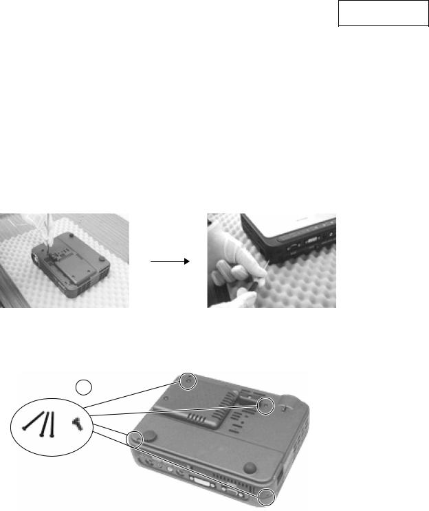
REMOVING OF MAJOR PARTS
Tools required
1.Philips screw driver (Size : 1, 2)
2.Nut driver (2.5mm)
3.Ball end hexagonal driver (5.0mm)
1.Disassemble Top Cover Module, Main PWB Unit and DC to DC PWB Unit
1-1. Remove four screws on Bottom Cover. (Refer to Step 1, 2.)
Step 1 |
Step 2 |
1-1
13

PG-M15X
PG-M15S
AN-M15T
1-2. Lift up Top Cover and unplug two wires connected to IR PWB Unit and Main Unit. (Refer to Step 3~5.) 1-3. Remove Top Cover.
1-4. Remove one screw to take off IR PWB Unit and IR PWB Unit Cover.
1-5. Remove four D-SUB shafts from the D-SUB Terminals to take off Terminal Sheet. (Refer to Step 6~7.)
1-2 |
1-2 |
Step 3 |
Step 4 |
Step 5 |
1-3
IR PWB Unit Cover
1-4
IR PWB Unit
Step 6
1-5
Terminal sheet
Step 7
14
PG-M15X
PG-M15S
AN-M15T
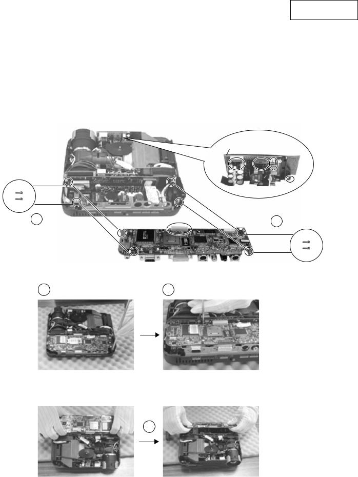
2. Disassemble Optical Engine Module
2-1. Remove 4 screws from main PWB unit.
2-2. Using a ball end hexagonal driver, loosen 2 screws holding terminal sheet holder. (approx. 4 rotation)(Step 8.)
2-3. Place a tool in between main PWB unit and formatter PWB unit and disconnect the connector. (Step 9.) 2-4. Pull the main unit outwards and remove main PWB unit. (Step 10,11.)
DC to DC PWB Unit
2-1 |
2-1 |
|
2-2 |
2-3 |
Step 8 |
Step 9 |
2-4
Step 10 |
Step 11 |
15

PG-M15X
PG-M15S
AN-M15T
2-5. Remove one screw of DC to DC PWB Unit Holder, unplug three Connecting Cords, and then detach DC to DC PWB Unit.
(Step 12,13.)
2-6. Remove push bar, push bar spring, and rubber. (refer to step 14~16.)
Cut three cable tie from Optical Engine Module.
Step 12
2-5
Unplug three Connecting Cords
of DC to DC PWB Unit
Step 13
2-6 |
2-6 |
Step 14 |
Step 15 |
Step 16 |
16

PG-M15X
PG-M15S
AN-M15T
2-7. Unplug six wires of Thermal PWB Unit. (Step 17.)
2-8. Remove 5 screws from optical engine module (Step 18~20.) 2-9. Remove 2 screws from projection lens cover. (Step 21.)
2-10. Remove optical engine module, projection lens cover, and Thermal Unit. (Step 22, 23.)
2-7
Step 17
2-8 |
2-8 |
Step 18 |
Step 19 |
2-9
Step 20 |
Step 21 |
2-10
Step 22 |
Step 23 |
17

PG-M15X
PG-M15S
AN-M15T
Projection Lens Cover
2-9
2-7
Speaker
Thermal PWB Unit
Optical Engine Module
2-8
DMD Off-Light Vent
2-6
Push Bar Spring
Pudh Bar
Leakage Rubber
18

PG-M15X
PG-M15S
AN-M15T
3. Disassemble Ballast PWB unit
3-1. Remove two screws and detach Terminal Sheet Holder. 3-2. Remove two screws and detach Grounding Sheet.
3-3. Remove two screws and detach AC Code Fix.
3-4. Remove two screws and detach ignitor cable from Lamp Housing. 3-5. Remove two screws and detach Ballast PWB unit.
3-4 
3-2 |
3-5 |
|
|
Grounding Sheet |
Ballast PWB unit |
3-3 |
|
AC Code Fix |
|
Terminal Sheet Holder
3-1
19

PG-M15X
PG-M15S
AN-M15T
4. Disassemble Lamp Housing
4-1. Loosen two screws and remove Lamp Cover. 4-2. Loosen three screws and lift Lamp.
4-3. Remove screw and detach Output Air Guide and Output Rubber duct. 4-4. Remove three screws and detach Lamp Housing.
4-5. Remove screw and nut then detach Fan from Lamp Housing.
4-6. Remove four screws and detach Blower Wind Guide from Lamp Housing. 4-7. Remove thermal Fuse from lamp Housing.
4-1
Lamp Cover
4-4
4-2 Lamp
4-6
Blower Wind
Guide Output 4-3 Rubber duct
Lamp Housing
Thermal Fuse
4-7
Output
Air Guide
Spacer
Fan
4-5
Bottom Cover
20
4-8. Remove screw and detach SW PWB unit and Interlock Protection Cover. 4-9. Remove screw and detach Thermal Switch.
4-8
Interlock Protection Cover
SW PWB unit
4-8
Bottom Cover
PG-M15X
PG-M15S
AN-M15T
Thermal
Switch 70°
4-9
21
PG-M15X
PG-M15S
AN-M15T
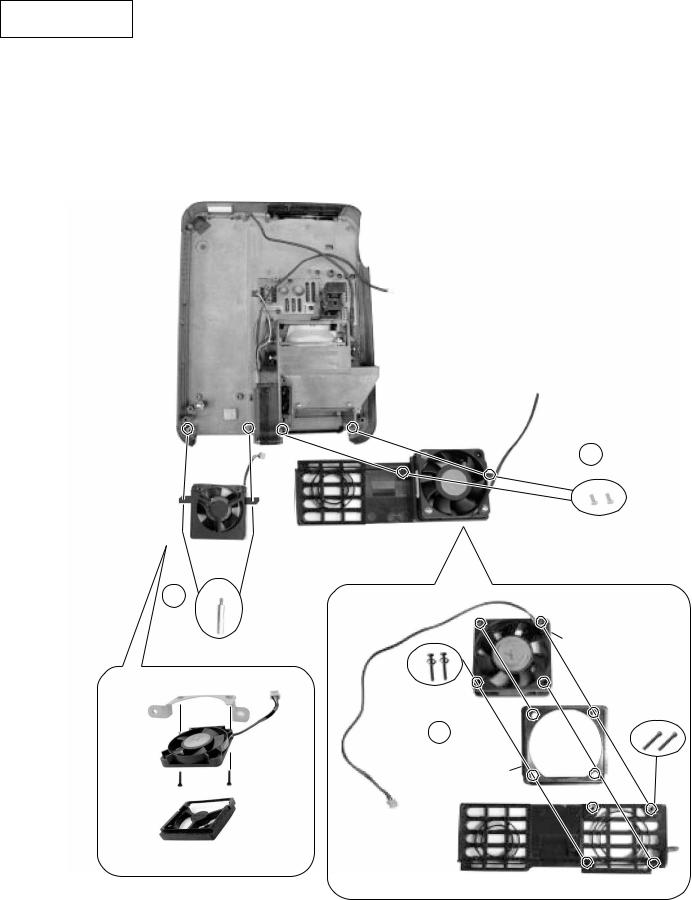
5. Disassemble Fan Module
5-1. Remove two Hexagon Copper Sticker and detach Assy Fan. 5-2. Remove two screws and detach Exhaust Window Assy. 5-3. Remove two screws and detach Fan and Rubber.
5-2
Fan Ass'y
Exhaust Window
5-1
Fan
Hexagon Copper Sticker
5-3
Fan
Rubber
Rubber
22

PG-M15X
PG-M15S
AN-M15T
RESETTING THE TOTAL LAMP TIMER
Maintenance Indicators
LAMP REPLACEMENT indicator
POWER indicator
TEMPERATURE WARNING indicator
•The warning lights on the projector indicate problems inside the projector.
•There are two warning lights: a TEMPERATURE WARNING indicator which warns that the projector is too hot, and a LAMP REPLACEMENT indicator which lets you know when to change the lamp.
•If a problem occurs, either the TEMPERATURE WARNING indicator or the LAMP REPLACEMENT indicator will illuminate red. After turning off the power, follow the procedures given below.
Maintenance Indicator |
Condition |
Problem |
Possible Solution |
|
|
|
|
|
|
TEMPERATURE |
The internal |
• Blocked air intake. |
• Relocate the projector to an area with proper |
|
WARNING |
temperature is |
|
ventilation. |
|
indicator |
abnormally high. |
|
|
|
• Cooling fan breakdown. |
• Take the projector to your nearest Sharp |
|||
|
|
|||
|
|
• Internal circuit failure. |
Authorized Projector Dealer or Service |
|
|
|
|
Center for repair. |
|
|
|
|
|
|
|
The indicator flashes in |
• Cooling down. |
• Wait until the indicator stops flashing and |
|
|
red. |
|
turns off. |
|
|
|
|
|
|
LAMP |
The lamp does not |
• Burnt-out lamp. |
• Carefully replace the lamp. |
|
REPLACEMENT |
illuminate. |
• Lamp circuit failure. |
|
|
indicator |
|
• The lamp caga cover is |
• Take the projector to your nearest Sharp |
|
|
|
not securely installed. |
Authorized Projector Dealer or Service |
|
|
|
|
Center for repair. |
|
|
The lamp requires |
• Lamp has been used for |
||
|
|
|||
|
replacement. |
over 1,400 hours. |
|
|
|
|
|
|
•If the TEMPERATURE WARNING indicator illuminates, follow the above possible solutions and then wait until the projector has cooled down completely before turning the power back on. (At least 5 minutes.)
•If the power is turned off and then turned on again, as during a brief rest, the LAMP REPLACEMENT indicator may be triggered, preventing the power from going on. Should this occur, take the power cord out of the wall outlet and put it back in again.
Resetting the lamp timer
1 cord.Connect the power |
2 Reset the lamp timer. |
|
|
|
|||||||||||
Plug the power cord into the AC |
1Press KEYSTONE (+) and |
“LAMP 0000H” is |
|||||||||||||
socket of the projector. |
KEYSTONE (–) simultaneously and |
displayed, indicating that |
|||||||||||||
|
|
|
|
|
|
ON/OFF at the same time. |
the lamp timer is reset. |
||||||||
|
|
|
|
|
|
|
|
1 |
|
|
|
|
|
|
|
|
|
|
|
|
|
|
|
|
|
|
|
|
|
|
|
|
|
|
|
|
|
|
|
|
|
|
|
|
|
|
|
|
|
|
|
|
|
|
|
|
|
|
|
|
|
|
|
|
|
|
|
|
|
|
|
|
|
|
|
|
|
|
|
|
|
|
|
|
|
|
|
|
|
|
|
|
|
|
|
|
|
|
|
|
|
|
|
|
|
|
|
|
|
|
|
|
|
|
|
|
|
|
|
|
|
|
|
|
|
|
|
|
|
|
|
|
|
|
|
|
|
|
|
|
|
|
|
|
|
|
|
|
|
|
|
|
|
|
|
|
|
|
|
|
|
|
|
|
|
|
|
|
|
|
|
|
|
|
|
» Reset the lamp timer only after replacing the lamp.
23

PG-M15X
PG-M15S
AN-M15T
Lamp
The lamp in this projector operates for approximately 1,500 cumulative hours, depending on the usage environment. It is recommended that the lamp be replaced after 1,400 cumulative hours of use or when you notice a significant deterioration of the picture and color quality. The lamp usage time can be checked with the On-screen Display.
 CAUTION
•Intense light hazard. Do not attempt to look into the aperture and lens while the projector is operating.
•As the usage environment can vary significantly, the projector lamp may not operate for 1,500 hours.
•“1,500 hours” above indicates average life span and should be used for reference only. This is different than the warranty period.
•For safety, the power will not be turned on from the fourth time when turning on the power without changing the lamp after use for 1,500 hours.
Condition |
Problem |
Possible Solution |
|
|
|
|
|
The LAMP REPLACEMENT indicator |
• Lamp has been used for |
• Purchase a replacement lamp unit (lamp |
|
illuminates red, and “LAMP” will appear in |
over 1,400 hours. |
cage/module) of the current type BQC- |
|
yellow in the lower-left corner of the picture. |
|
PGM15X//1 from your nearest Sharp |
|
|
|
Authorized Projector Dealer or Service |
|
A significant deterioration of the picture and |
|
||
|
Center. |
||
color quality occurs. |
|
||
|
• Replace the lamp. |
||
|
|
||
The power will automatically turn off and |
• Lamp has been used for |
||
If you wish, you may have the lamp |
|||
the projector will enter standby mode. |
over 1,500 hours. |
||
replaced at your nearest Sharp Authorized |
|||
|
|
||
“LAMP” will appear in red in the lower-left |
|
||
|
Projector Dealer or Service Center. |
||
corner of the picture, and the power will |
|
|
|
turn off. |
|
|
|
|
|
|
1 Turn off the power. |
2 cord.Disconnect the power |
3 cover.Remove the lamp cage |
Press ON/OFF on the projector |
Unplug the power cord from the |
Turn over the projector and |
or POWER on the remote |
AC socket. |
loosen the user service screws |
control. Wait until the cooling |
|
that secure the lamp cage cover. |
fan stops. |
|
Then lift open the cover in the |
|
|
direction of the arrow. |
or |
|
|
4 cage.Remove the lamp |
5 Insert the new lamp cage. |
6 cover.Attach the lamp cage |
Loosen the securing screws on |
Press the lamp cage firmly into |
Slide the lamp cage cover in the |
the lamp cage. Hold the lamp |
the lamp cage compartment. |
direction of the arrow. Then |
cage by the handle and pull it |
Fasten the securing screws. |
tighten the user service screws. |
towards you. |
|
|
24

PG-M15X
PG-M15S
AN-M15T
OPTICAL ADJUSTMENT AND MEASURING
1. Adjustment of Color Wheel Sensor
»Adjustment needed
1.When the color wheel unit has been replaced.
2.When the color wheel sensor has been replaced.
3.When the optical drive unit has been replaced (If a deviation from normal setting is found).
»Tools Required
1.Personal computer (run on Windows 95/98)
2.RGB cable
25
PG-M15X
PG-M15S
AN-M15T
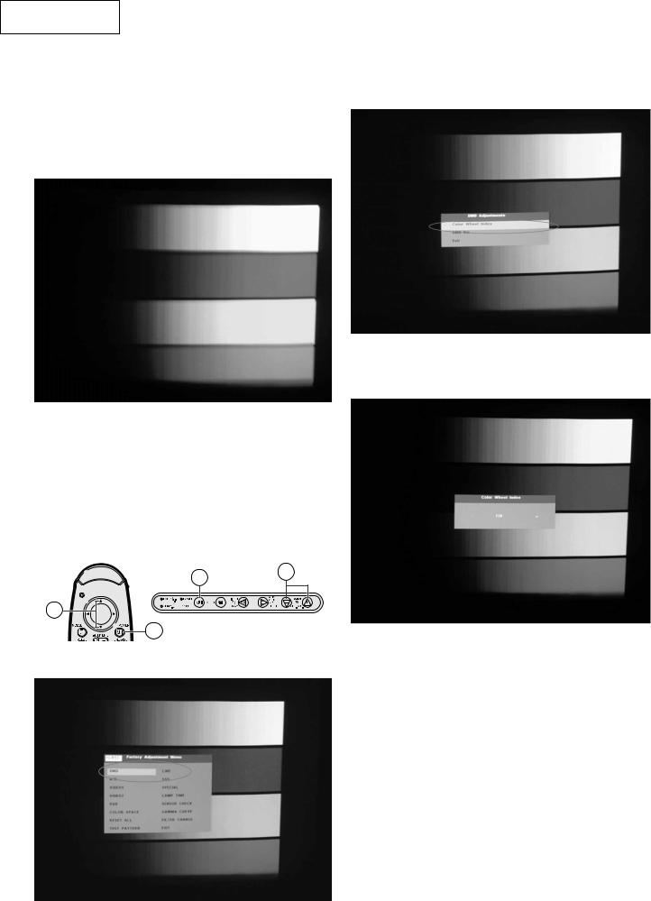
2. Color Wheel Index Adjustment
1.Choose R.G.B.W 4-color image.
1-1. Execute the “M15 Pattern dmw” command.
1-2. Click on “Color and Gray Scale”.
1-3. Left-click on the mouse to switch the pattern and to provide the “R.G.B.W 4-color Image” (64 Intensities for Primary Colors) output.
3. Choose "Color Wheel Index" to do adjustment.
4.Use "+" and "-" keys on Keypad to adjust the value to make the image have no abnormal color.
2.Select “DMD” on the process mode screen.
2-1. Turn on the power. Press the ON/OFF button on the projector or the POWER button on the remote controller.
2-2. Make sure the message “Turn Power OFF?” on the screen. With this message still onscreen, press the buttons in this order: “'”, “'”, “"” and “"” on the remote controller, or “+”, “+”, “-” and “-” on the projector.
2-3. Be sure the process adjustment menu appears on the screen, and select DMD.
2-2
2-1
2-2
Projector
2-1
RemoteController
5.Press "Enter" key and "MENU" to go back to the original image.
26

PG-M15X
PG-M15S
AN-M15T
3. DMD Type Setting Sop
1.Record type of DMD chip (An English letter in capital) before assembly.
3. Choose "DMD Bin" to do setting.
2.Select “DMD” on the process mode screen.
2-1. Turn on the power. Press the ON/OFF button on the projector or the POWER button on the remote controller.
2-2. Make sure the message “Turn Power OFF?” on the screen. With this message still onscreen, press the buttons in this order: “'”, “'”, “"” and “"” on the remote controller, or “+”, “+”, “-” and “-” on the projector.
2-3. Be sure the process adjustment menu appears on the screen, and select DMD.
2-2
2-1
2-2
Projector
2-1
RemoteController
4.Use "+" and "-" keys on Keypad to choose DMD type same as the type of new one
5.Press "Enter" key and then Press "MENU" key to go back to the original image.
Note: Be sure to make this DMD Type Setting to keep up the DMD chip reliability.
27
PG-M15X
PG-M15S
AN-M15T
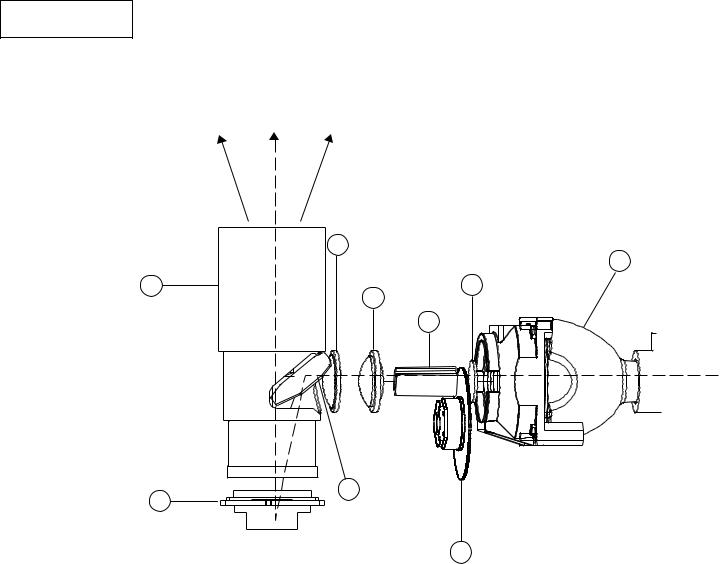
THE OPTICAL UNIT OUTLINE
<Conceptual Drawing>
Condenser
Lens 2
|
6 |
|
Lamp |
Projection Zoom Lens |
|
1 |
|
Condenser |
UV-IR Filter |
||
8 |
Lens 1 |
2 |
|
5 Rod Lens |
|
||
|
|
|
4
DMD Chip |
7 |
|
9 |
||
Reflection Mirror |
||
|
|
|
3 |
Color Wheel |
1. |
OSRAM Elliptical Reflector Kind of |
6. |
Condenser Lens 2 |
|
HID Lamp 130W |
7. |
Reflection Mirror |
|
|
||
2. |
UV-IR Filter |
8. |
Projection Zoom Lens |
3. |
Color Wheel |
9. |
DMD Chip |
|
|
4.Rod Lens
5.Condenser Lens 1
<Basic Functions> |
|
» UV-IR Filter |
: Filtering UV-IR out. |
» Color Wheel |
: Separating the light beam into and produce R.G.B colors. |
» Rod Lens |
: Making the light beam uniform. |
» Condenser Lens 1, 2 |
: Condenses the illumination of Rod Lens and projects it to the effective area of |
|
the reflection mirror. |
» Reflection Mirror |
: This mirror reflects the light rojected to the effection area of the DMD. |
» Projection Zoom Lens |
: Image from the DMD Chip will be projected on the screen through projection lens. |
» DMD Chip |
: This chip turns on and off in proportion to each color component per dot depending |
|
on the in put source. |
28

PG-M15X
PG-M15S
AN-M15T
Æ Precautions in disassembling the optical mechanism
Note: If the optical mechanism needs repairs, preferably replace the entire optical mechanism assembly with new one. This is because to very fine adjustments are needed for some parts.
Reflection mirror
Place back just in the same position and direction. Otherwise shades may appear on the projector screen. Each positioning is needed.
Projection lens This lens cannot be disassembled.
Rod lens
Place back just in the same position and direction. Otherwise shades may appear on the projector screen. Each positioning is needed.
Color wheel
Once disassembled, this part may need readjustment.
Condenser lens 1 and 2 Place back just in the same position and direction. Otherwise shades may appear on the projector screen. Each positioning is needed.
DMD assembly
This assembly can be disassembled. But be careful not to allow dust and fingerprint on it. Otherwise the images may be adversely affected.
If the rod lens or mirror has not been correctly adjusted, there will be shades on the projection screen.
Æ Initial factory settings
These models require no additional electrical adjustment. If by any chance the factory settings must be made again, however, call the process adjustment mode first in the following procedure.
1.Calling the process adjustment mode
1)Turn on the power. Press the ON/OFF button on the projector or the POWER button on the remote controller.
2)Make sure the message “Turn Power OFF?” on the screen. With this message still onscreen, press the buttons in this order: “'”, “'”, “"” and “"” on the remote controller, or “+”, “+”, “-” and “-” on the projector.
3)Be sure the process adjustment menu appears on the screen.
2.Using the “'” and “"” buttons on the remote controller or the “+” and “-” buttons on the projector, select “SSS” and press the “ENTER” key.
3.Using the “'” and “"” buttons on the remote controller or the “+” and “-” buttons on the projector, select the following setting according to the destination and press the “ENTER” key.
Setting |
Destination |
"S4" |
Europe, Asia, Oceania |
"S6" |
North America |
29

PG-M15X
PG-M15S
AN-M15T
TROUBLE SHOOTING TABLE
1.Equipment Needed
»PG-M15X/S
»VGA Cable, Power Cord
»PC (Personal Computer)
»Audio Input, Video Input
»Screw Driver
2.Main Procedure
Start
Connect AC cord, VGA cable and audio signal, then turn power on
No
Is Lamp light on?
Yes
No
Is Image OK?
Yes
No
Is function OK?
Yes
No
Is Audio OK?
Yes
No
Is Remote Control OK?
Yes
No Fault Found
A.Power Troubleshooting
B.Image Performance Troubleshooting
C.Function Troubleshooting
D.Audio Troubleshooting
Change Remote Control unit
End
30
 Loading...