


LC-32LE705E
Sharp LC-32LE705E, LC-32LE705S, LC-32LU705E, LC-32LU705S, LC-32LX705E Service Manual
...
LC-32/40/46LE705E/S, LU705E/S, LX705E, LC-52LE705E/S
SERVICE MANUAL
No. SX9D1LC32L705
LCD COLOUR TELEVISION
LC-32LE705E/S, LC-32LU705E/S
LC-32LX705E
LC-40LE705E/S, LC-40LU705E/S
LC-40LX705E
LC-46LE705E/S, LC-46LU705E/S
LC-46LX705E
MODELS
In the interests of user-safety (Required by safety regulations in some countries) the set should be restored to its original
condition and only parts identical to those specified should be used.
LC-52LE705E/S
OUTLINE
LC-32/40/46LE705E/S, LU705E/S, LX705E, LC-52LE705E/S has been issued to cover the modifications of some parts in reference
to redesigned LCD panel module of Model LC-32/40/46/52LE700E/S. In this Service Manual, the modifications from Model LC-32/
40/46/52LE700E/S (No. S89B4LC32L700) are focused on. For what is left out herein, please refer back to the Service Manual of
the previous model LC-32/40/46/52LE700E/S (No. S89B4LC32L700).
CONTENTS
OUTLINE AND DIFFERENCES FROM BASE MODEL
OUTLINE.............................................................i
LIST OF CHANGED PARTS
(LC-32LE705E/S, LU705E/S, LX705E)...............i
LIST OF CHANGED PARTS
(LC-40LE705E/S, LU705E/S, LX705E)..............ii
LIST OF CHANGED PARTS
(LC-46LE705E/S, LU705E/S, LX705E).............iii
LIST OF CHANGED PARTS
(LC-52LE705E/S)..............................................iv
SAFETY PRECAUTION
IMPORTANT SERVICE SAFETY
PRECAUTION....................................................v
Precautions for using lead-free solder ..............vi
End of life disposal ........................................... vii
CHAPTER 3. MAJOR IC INFORMATIONS
[1] MAJOR IC INFORMATIONS .........................3-1
CHAPTER 4. OVERALL WIRING/SYSTEM BLOCK
DIAGRAM
[1] OVERALL WIRING DIAGRAM ......................4-1
[2] SYSTEM BLOCK DIAGRAM .........................4-5
CHAPTER 5. PRINTED WIRING BOARD
ASSEMBLIES
[1] MAIN Unit ......................................................5-1
CHAPTER 6. SCHEMATIC DIAGRAM
[1] DESCRIPTION OF SCHEMATIC
DIAGRAM...................................................... 6-1
[2] SCHEMATIC DIAGRAM................................6-2
CHAPTER 1. REMOVING OF MAJOR PARTS
[1] REMOVING OF MAJOR PARTS ................... 1-1
CHAPTER 2. ADJUSTMENT
[1] ADJUSTMENT PROCEDURE ....................... 2-1
Parts marked with " " are important for maintaining the safety of the set. Be sure to replace these parts with specified ones for maintaining the
safety and performance of the set.
Parts Guide
This document has been published to be used for
after sales service only.
The contents are subject to change without notice.
LC-32/40/46LE705E/S, LU705E/S, LX705E, LC-52LE705E/S
LC-32LE705E
OUTLINE AND DIFFERENCES FROM BASE MODEL
Service Manual
OUTLINE
LC-32/40/46LE705E/S, LU705E/S, LX705E, 52LE705E/S has been issued to cover the modifications of some parts in reference to redesigned LCD
panel module of Model LC-32/40/46/52LE700E/S. In this Service Manual, the modifications from Model LC-32/40/46/52LE700E/S (No.
S89B4LC32L700) are focused on. For what is left out herein, please refer back to the Service Manual of the previous model LC-32/40/46/52LE700E/
S (No. S89B4LC32L700).
LIST OF CHANGED PARTS (LC-32LE705E/S, LU705E/S, LX705E)
Ref No. Description LC-32LE/LU/LX700E/S
(No. S89B4LC32L700)
PRINTED WIRING BOARD ASSEMBLIES
MAIN Unit DUNTKF306FM01 DKEYDF306FM10 D Changed
KEY Unit DUNTKE266FM18 ← — No change
R/C, LED Unit DUNTKF308FM02 ← — No change
ICON Unit DUNTKF314FM02 ← — No change
POWER Unit RUNTKA619WJQZ ← — No change
LCD Control Unit RUNTK4225TPZU ← — No change
LED5-PWB1 Unit RUNTKA655WJ01 ← — No change
LED5-PWB2 Unit RUNTKA655WJ02 ← — No change
LED8-PWB1 Unit RUNTKA658WJ01 ← — No change
LED8-PWB2 Unit RUNTKA658WJ02 ← — No change
LCD PANEL
32" LCD Panel Module Unit DLCUCA001FM03 ← — No change
MAIN Unit
IC2002 IC RH-iXC786WJN5Q RH-iXC786WJNAQ D Changed
IC3302 IC RH-iXC773WJQZQ RH-iXC951WJQZQ D Changed
CABINET AND MECHANICAL PARTS
Please refer to a Parts list
LCD MODULE Assembly
Please refer to a Parts list
SUPPLIED ACCESSORIES
Please refer to a Parts list
PACKING PARTS (NOT REPLACEMENT ITEM)
Please refer to a Parts list
NOTE: If it is necessary to replace IC8401 and IC3302, replace the main unit.
LC-32LE/LU705E/S/LX705E
(No. SX9D1LC32L705 )
Interchangeability Note
Completely interchangeableA:
Interchangeable from
B:
OLD to NEW
Interchangeability
=
NEWOLD
NEWOLD
Interchangeable from
C:
NEW to OLD
Not interchangeableD:
i
NEW OLD
X
OLDNEW

LC-32/40/46LE705E/S, LU705E/S, LX705E, LC-52LE705E/S
LIST OF CHANGED PARTS (LC-40LE705E/S, LU705E/S, LX705E)
Ref No. Description LC-40LE/LU/LX700E/S
(No. S89B4LC32L700)
PRINTED WIRING BOARD ASSEMBLIES
MAIN Unit DUNTKF306FM01 DKEYDF306FM10 D Changed
KEY Unit DUNTKE266FM18 ← — No change
R/C, LED Unit DUNTKF308FM02 ← — No change
ICON Unit DUNTKF314FM02 ← — No change
POWER Unit RUNTKA642WJQZ ← — No change
LCD Control Unit RUNTK4225TPZU ← — No change
LED5-PWB1 Unit RUNTKA655WJ01 ← — No change
LED5-PWB2 Unit RUNTKA655WJ02 ← — No change
LED6-PWB1 Unit RUNTKA656WJ01 ← — No change
LED6-PWB2 Unit RUNTKA656WJ02 ← — No change
LCD PANEL
40" LCD Panel Module Unit DLCUCA002FM07 ← — No change
MAIN Unit
IC2002 IC RH-iXC786WJN5Q RH-iXC786WJNAQ D Changed
IC3302 IC RH-iXC773WJQZQ RH-iXC951WJQZQ D Changed
CABINET AND MECHANICAL PARTS
Please refer to a Parts list
LCD MODULE Assembly
Please refer to a Parts list
SUPPLIED ACCESSORIES
Please refer to a Parts list
PACKING PARTS (NOT REPLACEMENT ITEM)
Please refer to a Parts list
NOTE: If it is necessary to replace IC8401 and IC3302, replace the main unit.
LC-40LE/LU705E/S/LX705E
(No. SX9D1LC32L705)
Interchangeability Note
Completely interchangeableA:
Interchangeable from
B:
OLD to NEW
Interchangeability
=
NEWOLD
NEWOLD
Interchangeable from
C:
NEW to OLD
Not interchangeableD:
NEW OLD
X
OLDNEW
ii
LC-32/40/46LE705E/S, LU705E/S, LX705E, LC-52LE705E/S
LIST OF CHANGED PARTS (LC-46LE705E/S, LU705E/S, LX705E)
Ref No. Description LC-46LE/LU/LX700E/S
(No. S89B4LC32L700)
PRINTED WIRING BOARD ASSEMBLIES
MAIN Unit DUNTKF306FM01 DKEYDF306FM10 D Changed
KEY Unit DUNTKE266FM18 ← — No change
R/C, LED Unit DUNTKF308FM02 ← — No change
ICON Unit DUNTKF314FM02 ← — No change
POWER Unit RUNTKA643WJQZ ← — No change
LCD Control Unit RUNTK4225TPZU ← — No change
LED5-PWB1 Unit RUNTKA655WJ01 ← — No change
LED5-PWB2 Unit RUNTKA655WJ02 ← — No change
LED6-PWB1 Unit RUNTKA656WJ01 ← — No change
LED6-PWB2 Unit RUNTKA656WJ02 ← — No change
LED8-PWB1 Unit RUNTKA658WJ01 ← — No change
LED8-PWB2 Unit RUNTKA658WJ02 ← — No change
LCD PANEL
46" LCD Panel Module Unit DLCUCA003FM07 ← — No change
MAIN Unit
IC2002 IC RH-iXC786WJN5Q RH-iXC786WJNAQ D Changed
IC3302 IC RH-iXC733WJQZQ RH-iXC951WJQZQ D Changed
CABINET AND MECHANICAL PARTS
Please refer to a Parts list
LCD MODULE Assembly
Please refer to a Parts list
SUPPLIED ACCESSORIES
Please refer to a Parts list
PACKING PARTS (NOT REPLACEMENT ITEM)
Please refer to a Parts list
NOTE: If it is necessary to replace IC8401 and IC3302, replace the main unit.
LC-46LE/LU705E/S/LX705E
(No. SX9D1LC32L705)
Interchangeability Note
Completely interchangeableA:
Interchangeable from
B:
OLD to NEW
Interchangeability
=
NEWOLD
NEWOLD
Interchangeable from
C:
NEW to OLD
Not interchangeableD:
NEW OLD
X
OLDNEW
iii

LIST OF CHANGED PARTS (LC-52LE705E/S)
LC-32/40/46LE705E/S, LU705E/S, LX705E, LC-52LE705E/S
Ref No. Description LC-52LE700E/S
(No. S89B4LC32L700)
PRINTED WIRING BOARD ASSEMBLIES
MAIN Unit DUNTKF306FM01 DKEYDF306FM10 D Changed
KEY Unit DUNTKE266FM18 ← — No change
R/C, LED Unit DUNTKF308FM02 ← — No change
ICON Unit DUNTKF314FM02 ← — No change
POWER Unit RUNTKA643WJQZ ← — No change
LCD Control Unit RUNTK4225TPZU ← — No change
LED6-PWB1 Unit RUNTKA656WJ01 ← — No change
LED6-PWB2 Unit RUNTKA656WJ02 ← — No change
LED8-PWB1 Unit RUNTKA658WJ01 ← — No change
LED8-PWB2 Unit RUNTKA658WJ02 ← — No change
LCD PANEL
52" LCD Panel Module Unit DLCUCA004FM07 ← — No change
MAIN Unit
IC2002 IC RH-iXC786WJN5Q RH-iXC786WJNAQ D Changed
IC3302 IC RH-iXC733WJQZQ RH-iXC951WJQZQ D Changed
CABINET AND MECHANICAL PARTS
Please refer to a Parts list
LCD MODULE Assembly
Please refer to a Parts list
SUPPLIED ACCESSORIES
Please refer to a Parts list
PACKING PARTS (NOT REPLACEMENT ITEM)
Please refer to a Parts list
NOTE: If it is necessary to replace IC8401 and IC3302, replace the main unit.
LC-52LE705E/S
(No. SX9D1LC32L705)
Interchangeability Note
Completely interchangeableA:
Interchangeable from
B:
OLD to NEW
Interchangeability
=
NEWOLD
NEWOLD
Interchangeable from
C:
NEW to OLD
Not interchangeableD:
NEW OLD
X
OLDNEW
iv

LC-32/40/46LE705E/S, LU705E/S, LX705E, LC-52LE705E/S
LC-32LE705E
SAFETY PRECAUTION
Service Manual
IMPORTANT SERVICE SAFETY PRECAUTION
Service work should be performed only by qualified service technicians who are thoroughly familiar with all safety checks and the
servicing guidelines which follow:
WARNING
1. For continued safety, no modification of any circuit should be
attempted.
2. Disconnect AC power before servicing.
CAUTION:
FOR CONTINUED PROTECTION AGAINST A
RISK OF FIRE REPLACE ONLY WITH SAME
TYPE FUSE.
32 inch model: F7001, F7002 (2.5A/250V)
40 inch model: F7001, F7002 (5A/250V)
46/52 inch model: F7001, F7002 (6.3A/250V)
BEFORE RETURNING THE RECEIVER
(Fire & Shock Hazard)
Before returning the receiver to the user, perform the following
safety checks:
3. Inspect all lead dress to make certain that leads are not pinched,
and check that hardware is not lodged between the chassis and
other metal parts in the receiver.
4. Inspect all protective devices such as non-metallic control knobs,
insulation materials, cabinet backs, adjustment and compartment
covers or shields, isolation resistor-capacitor networks, mechanical
insulators, etc.
5. To be sure that no shock hazard exists, check for leakage current in
the following manner.
• Plug the AC cord directly into a 220~240 volt AC outlet.
• Using two clip leads, connect a 1.5k ohm, 10 watt resistor paralleled by a 0.15µF capacitor in series with all exposed metal cabinet
parts and a known earth ground, such as electrical conduit or electrical ground connected to an earth ground.
• Use an AC voltmeter having with 5000 ohm per volt, or higher, sensitivity or measure the AC voltage drop across the resistor.
• Connect the resistor connection to all exposed metal parts having a
return to the chassis (antenna, metal cabinet, screw heads, knobs
and control shafts, escutcheon, etc.) and measure the AC voltage
drop across the resistor.
All checks must be repeated with the AC cord plug connection
reversed. (If necessary, a nonpolarized adaptor plug must be used
only for the purpose of completing these checks.)
Any reading of 1.05 V peak (this corresponds to 0.7 mA peak AC.)
or more is excessive and indicates a potential shock hazard which
must be corrected before returning the monitor to the owner.
DVM
AC SCALE
1.5k ohm
10W
0.15µF
TEST PROBE
///////////////////////////////////////////////////////////////////////////////////////////////////////////////////////////////////////////////////////////////////////////////////////////////////////////////////////////////////////////
SAFETY NOTICE
Many electrical and mechanical parts in LCD color television have
special safety-related characteristics.
These characteristics are often not evident from visual inspection, nor
can protection afforded by them be necessarily increased by using
replacement components rated for higher voltage, wattage, etc.
Replacement parts which have these special safety characteristics are
identified in this manual; electrical components having such features
are identified by “ ” and shaded areas in the Replacement Parts
List and Schematic Diagrams.
///////////////////////////////////////////////////////////////////////////////////////////////////////////////////////////////////////////////////////////////////////////////////////////////////////////////////////////////////////////
TO EXPOSED
METAL PARTS
For continued protection, replacement parts must be identical to those
used in the original circuit.
The use of a substitute replacement parts which do not have the same
safety characteristics as the factory recommended replacement parts
shown in this service manual, may create shock, fire or other hazards.
CONNECT TO
KNOWN EARTH
GROUND
v

LC-32/40/46LE705E/S, LU705E/S, LX705E, LC-52LE705E/S
Precautions for using lead-free solder
Employing lead-free solder
• “PWBs” of this model employs lead-free solder. The LF symbol indicates lead-free solder, and is attached on the PWBs and service manuals. The
alphabetical character following LF shows the type of lead-free solder.
Example:
L Fa
Indicates lead-free solder of tin, silver and copper.
Indicates lead-free solder of tin, silver and copper.
L F a/a
Using lead-free wire solder
• When fixing the PWB soldered with the lead-free solder, apply lead-free wire solder. Repairing with conventional lead wire solder may cause damage or accident due to cracks.
As the melting point of lead-free solder (Sn-Ag-Cu) is higher than the lead wire solder by 40 °C, we recommend you to use a dedicated soldering
bit, if you are not familiar with how to obtain lead-free wire solder or soldering bit, contact our service station or service branch in your area.
Soldering
• As the melting point of lead-free solder (Sn-Ag-Cu) is about 220 °C which is higher than the conventional lead solder by 40 °C, and as it has poor
solder wettability, you may be apt to keep the soldering bit in contact with the PWB for extended period of time. However, Since the land may be
peeled off or the maximum heat-resistance temperature of parts may be exceeded, remove the bit from the PWB as soon as you confirm the
steady soldering condition.
Lead-free solder contains more tin, and the end of the soldering bit may be easily corroded. Make sure to turn on and off the power of the bit as
required.
If a different type of solder stays on the tip of the soldering bit, it is alloyed with lead-free solder. Clean the bit after every use of it.
When the tip of the soldering bit is blackened during use, file it with steel wool or fine sandpaper.
• Be careful when replacing parts with polarity indication on the PWB silk.
Lead-free wire solder for servicing
Part No. Description Code
ZHNDAi123250E J φ0.3mm 250g (1roll) BL
ZHNDAi126500E J φ0.6mm 500g (1roll) BK
ZHNDAi12801KE J φ1.0mm 1kg (1roll) BM
vi

LC-32/40/46LE705E/S, LU705E/S, LX705E, LC-52LE705E/S
End of life disposal
End of life disposal
A. Information on Disposal for Users (private households)
1. In the European Union
Attention: If you want to dispose of this equipment, please do not use the ordinary dust bin!
Used electrical and electronic equipment must be treated separately and in accordance with legislation that
requires proper treatment, recovery and recycling of used electrical and electronic equipment.
Following the implementation by member states, private households within the EU states may return their
used electrical and electronic equipment to designated collection facilities free of charge*. In some countries*
your local retailer may also take back your old product free of charge if you purchase a similar new one.
Attention: Your
product is marked
with this symbol.
It means that used
electrical and
electronic products
should not be
mixed with general
household waste.
There is a separate
collection system for
these products.
*) Please contact your local authority for further details.
If your used electrical or electronic equipment has batteries or accumulators, please dispose of these
separately beforehand according to local requirements.
By disposing of this product correctly you will help ensure that the waste undergoes the necessary treatment,
recovery and recycling and thus prevent potential negative effects on the environment and human health
which could otherwise arise due to inappropriate waste handling.
2. In other Countries outside the EU
If you wish to discard this product, please contact your local authorities and ask for the correct method of
disposal.
For Switzerland: Used electrical or electronic equipment can be returned free of charge to the dealer, even if
you don’t purchase a new product. Further collection facilities are listed on the homepage of www.swico.ch
or www.sens.ch.
B. Information on Disposal for Business Users
1. In the European Union
If the product is used for business purposes and you want to discard it:
Please contact your SHARP dealer who will inform you about the take-back of the product. You might be
charged for the costs arising from take-back and recycling. Small products (and small amounts) might be
taken back by your local collection facilities.
For Spain: Please contact the established collection system or your local authority for take-back of your used
products.
2. In other Countries outside the EU
If you wish to discard of this product, please contact your local authorities and ask for the correct method of
disposal.
The battery supplied with this product contains traces of Lead.
For EU: The crossed-out wheeled bin implies that used batteries should not be put to the general household
waste! There is a separate collection system for used batteries, to allow proper treatment and recycling in
accordance with legislation. Please contact your local authority for details on the collection and recycling
schemes.
For Switzerland: The used battery is to be returned to the selling point.
For other non-EU countries: Please contact your local authority for correct method of disposal of the used
battery.
vii

LC-32LE705E
CHAPTER 1. REMOVING OF MAJOR PARTS
Service Manual
[1] REMOVING OF MAJOR PARTS
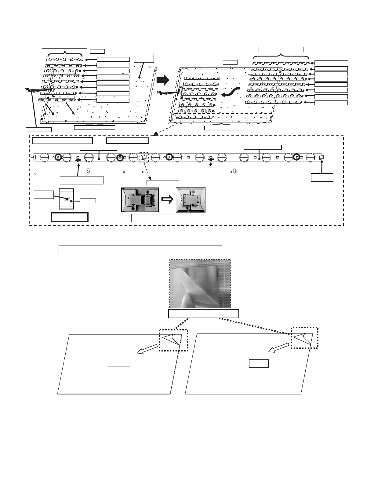
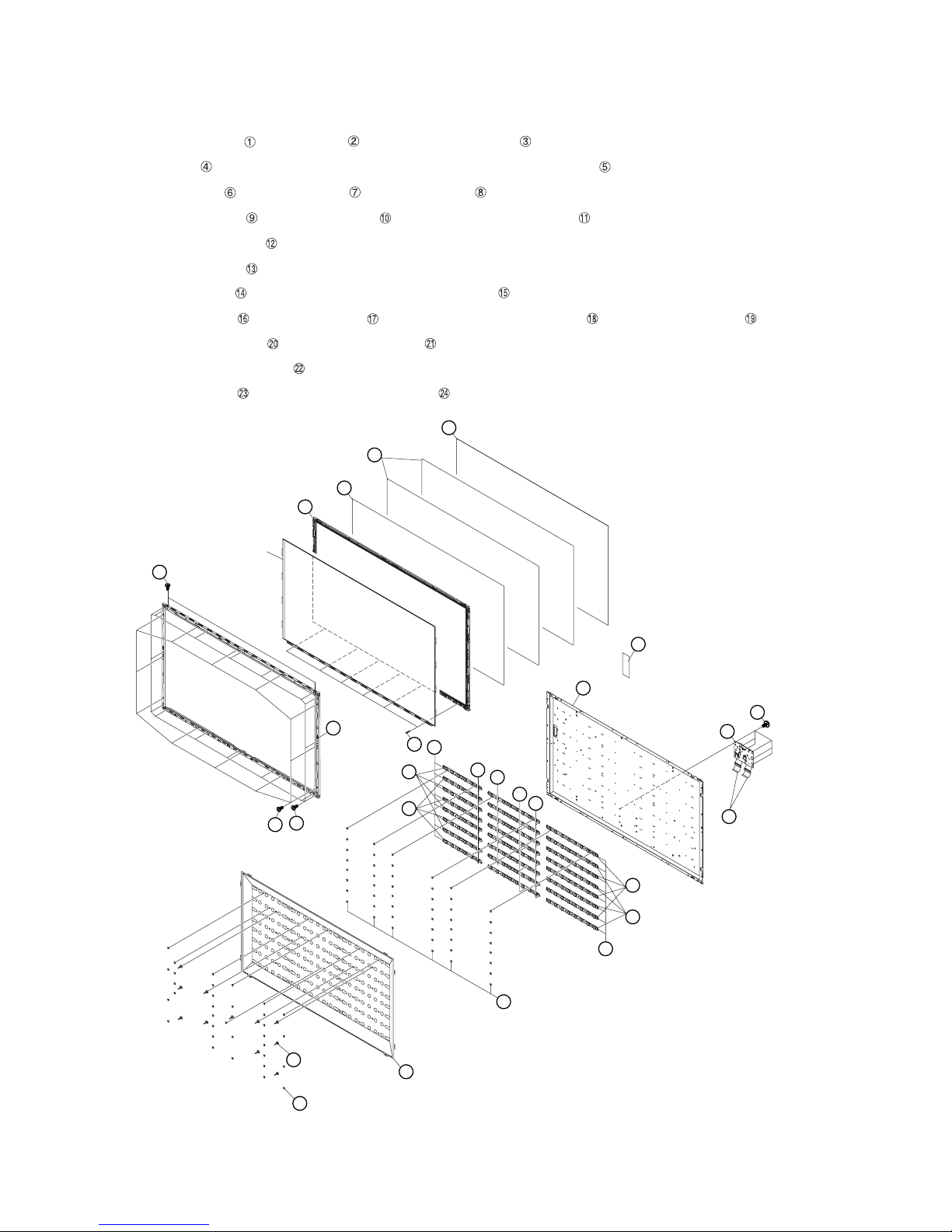
1. Removing of Bezel Ass’y, Panel Chassis Ass’y, Optical Sheet, Lens Sheet, Diffusion Plate, Back Light Chas-
sis and LCD Control Unit (32 inch models).
NOTE: A clean booth is required for repair of the component units and/ or parts (LCD Panel HIRAKI, LED PWB etc.) inside the LCD panel module
unit.
1. Remove the 10 lock screws ,10 lock screws and detach the Bezel Ass’y .
2. Detach the 32” LCD Panel HIRAKI Unit and Panel Chassis Ass’y .
3. Detach the Optical sheet and Lens Sheet and Micro Lens Sheet Diffusion Plate .
4. Remove the 16 Push Rivets and 4 Support Pins and detach the Reflection Sheet .
5. Remove the 32 Push Rivets .
6. Remove the 8 Terminators and 8 connections and detach the 4 LED8 PWB1 Units and 4 LED8 PWB2 Units .
7. Detach the 4 LED5 PWB1 Units and 4 LED5 PWB2 Units .
8. Disconnect the connecting cords from the 8 connectors of the LED5 PWB1/2 Unit.
9. Detach the Back Light Chassis .
10.Detach the 2 Connecting Cord and 2 Ferrite Core .
LC-32/40/46LE705E/S, LU705E/S, LX705E, LC-52LE705E/S
11.Remove the 6 lock screws and detach the LCD Control Unit
5
Optical Sheet
32" LCD
Panel HIRAKI Unit
Bezel Ass'y
3
Panel Chassis
Ass'y
1
Lens Sheet
4
2
Micro Lens Sheet
6
19
18
17
14
7
Diffusion Plate
LCD Control
Unit
Back Light
Chassis
20
8
23
24
Connecting Cord
Ferrite Core
21
22
Support Pin
Push Rivet
9
10
16
15
13
12
Reflection Sheet
11
1 – 1
LC-32/40/46LE705E/S, LU705E/S, LX705E, LC-52LE705E/S
2. Handling notes (32 inch models).
1. Set and connect LED-PWBs.
RUNTKA655WJ01 / WJ02
WIRE HA RNES S
Set and connect LED-PWBs
LED-PWB set direction
(arrow mark to harness side)
Boss o f
BL-CHASSIS
Boss fitting
(showing in blue c ircl es)
Top Sid e
RUNTKA655WJ01
RUNTKA655WJ02
RUNTKA655WJ01
RUNTKA655WJ02
RUNTKA655WJ01
RUNTKA655WJ02
RUNTKA655WJ01
RUNTKA655WJ02
Bottom Side (C-PWB s ide)
RUNTKA655WJ01/02
LED-PWB
INSIDE of
BL-CHASSIS
*Same for other 7 lines.
Insert the connector hor izont ally mutually.
Do not addinadequate power.
Connect LED -PW Bs
Bottom Side (C-PWB side)
LED-PWB set direction
(arrow mark to harnes s s ide)
Top Sid e
RUNTKA658WJ01 / WJ02
RUNTKA658 WJ01 /02
RUNTKA658WJ01
RUNTKA658WJ02
RUNTKA658WJ01
RUNTKA658WJ02
RUNTKA658WJ01
RUNTKA658WJ02
RUNTKA658WJ01
RUNTKA658WJ02
TERMINATOR
is Attach ed
2. Peel off the lamination film of LENS SHEET on the both sides.
Pee l off the lamina tion film of LENS SHEET on the both sides.
FRONT
Pee l off the lamination film.
BACK
1 – 2

LC-32/40/46LE705E/S, LU705E/S, LX705E, LC-52LE705E/S
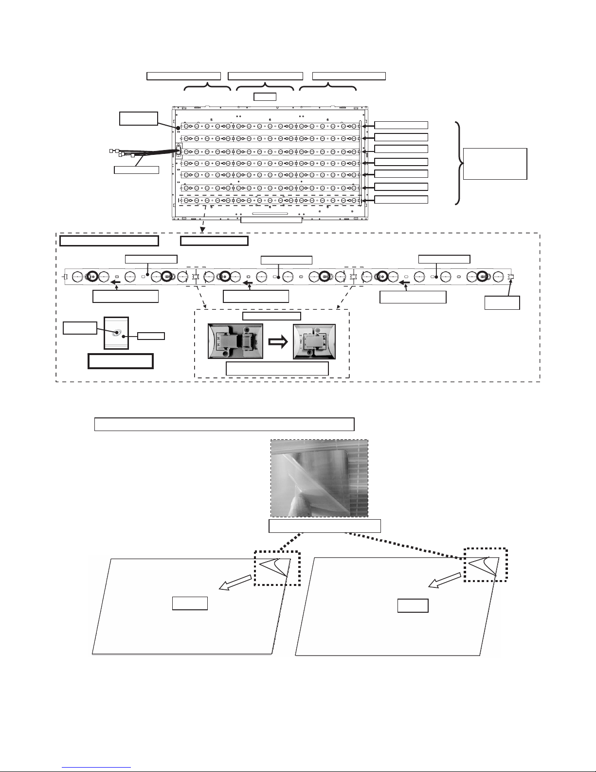
3. Removing of Bezel Ass’y, Panel Chassis Ass’y, Lens Sheet, Diffusion Plate, Back Light Chassis and LCD
Control Unit (40 inch models).
NOTE: A clean booth is required for repair of the component units and/ or parts (LCD Panel HIRAKI, LED PWB etc.) inside the LCD panel module
unit.
1. Remove the 14 lock screws ,12 lock screws and detach the Bezel Ass’y .
2. Remove the 4 Clips and detach the 40” LCD Panel HIRAKI Unit and Panel Chassis Ass’y .
3. Detach the DBEF Sheet and 2 Lens Sheet and Diffusion Plate .
4. Remove the 20 Push Rivets and 8 Support Pins and detach the Reflector Sheet .
5. Detach the 2 Connection Cords .
6. Remove the 42 Push Rivets .
7. Detach the Bush Cap Unit and connecting cords from the 7 Connectors of the LED5-PWB1/2 Unit.
8. Remove the 7 Terminators and 14 connections and detach the 8 LED6-PWB1 Units and 6 LED6-PWB2 Units .
9. Detach the 4 LED5-PWB1 Units and 3 LED5-PWB2 Units .
10.Detach the Back Light Chassis Ass’y .
11.Detach the 2 Ferrite Cores .
12.Remove the 6 lock screws and detach the LCD Control Unit .
Diffusion Plate 8
Lens Sheet 7
Panel Chassis Ass'y
40" LCD Panel HIRAKI Unit
3 Bezel Ass'y
1
DBEF Sheet 6
5
2
14 Bush Cap Unit
22
Back Light Chassis Ass'y
Clip4
15
21
20
17
18
19
17
19
18
16
25LCD Control Unit
2324Ferrite Core
12 Connecting Cord
13
Support Pin10
Reflector Sheet11
Push Rivet9
1 – 3
LC-32/40/46LE705E/S, LU705E/S, LX705E, LC-52LE705E/S
4. Handling notes (40 inch models).
1. Set and connect LED-PWBs.
INSIDE of
BL-CHASSIS
WIRE HARNESS
Set and connect LED-PWBs
RUNTKA655WJ**
LED-PWB set direction
(arrow mark to harness side)
Boss of
BL-CHASSIS
(showing in blue circles)
Boss fitting
LED-PWB
RUNTKA655WJ01 / WJ02
*Same for other lines.
RUNTKA656WJ01 / WJ02 RU NTKA656WJ01 / WJ02
Top Side
Bottom Side (C-PWB side)
RUNTKA656WJ**
LED-PWB set direction
(arrow mark to harness side)
Connect LED-PWBs
Insert the connector horizontally mutually.
Do not add impossible power.
RUNTKA***WJ01
RUNTKA***WJ02
RUNTKA***WJ01
RUNTKA***WJ02
RUNTKA***WJ01
RUNTKA***WJ02
RUNTKA***WJ01
RUNTKA656WJ**
LED-PWB set direction
(arrow mark to harness side)
㧨CAUTION㧪
It being alternated
RUNTKA***WJ01
and RUNTKA***WJ02.
TERMINATOR
is Attached
2. Peel off the lamination film of LENS SHEET on the both sides.
Pee l off the lamina tion film of LENS SHEET on the both sides.
FRONT
Pee l off the lamination film.
BACK
1 – 4

LC-32/40/46LE705E/S, LU705E/S, LX705E, LC-52LE705E/S
5. Removing of Bezel Ass’y, Panel Chassis Ass’y, Lens Sheet, Diffusion Plate, Back Light Chassis and LCD
Control Unit (46 inch models).
NOTE: A clean booth is required for repair of the component units and/ or parts (LCD Panel HIRAKI, LED PWB etc.) inside the LCD panel module
unit.
1. Remove the 10 lock screws ,16 lock screws and detach the Bezel Ass’y .
2. Remove the 4 Clips and detach the 46” LCD Panel HIRAKI Unit and Panel Chassis Ass’y .
3. Detach the DBEF Sheet and 2 Lens Sheet and Diffusion Plate .
4. Remove the 23 Push Rivets and 11 Support Pins and detach the Reflector Sheet .
5. Detach the 2 Connection Cords .
6. Remove the 48 Push Rivets .
7. Detach the Bush Cap Unit and connecting cords from the 8 connectors of the LED5-PWB1/2 Unit.
8. Remove the 8 Terminators and 16 connections and detach the 4 LED8-PWB1 Units , 4 LED8-PWB2 Units , 4 LED6-PWB1 Units
and 4 LED6-PWB2 Units .
9. Detach the 4 LED5-PWB1 Units and 4 LED5-PWB2 Units .
10.Detach the Back Light Chassis .
11.Detach the 2 Ferrite Cores .
12.Remove the 6 lock screws and detach the LCD Control Unit .
Diffusion Plate 8
Lens Sheet 7
Panel Chassis Ass'y 5
46" LCD Panel HIRAKI Unit
3 Bezel Ass'y
1
DBEF Sheet 6
2
14 Bush Cap Unit
24 Back Light Chassis
4
Clip
15
22
23
17
20
21
17
18
19
16
27LCD Control Unit
2526Ferrite Core
12 Connecting Cord
Support Pin10
Push Rivet9
13
Reflector Sheet11
1 – 5

LC-32/40/46LE705E/S, LU705E/S, LX705E, LC-52LE705E/S
6. Handling notes (46 inch models).
1. Set and connect LED-PWBs.
INSIDE of
BL-CHASSIS
WIRE HARNESS
Set and connect LED-PWBs
RUNTKA655WJ**
LED-PWB set direction
(arrow mark to harness side)
Boss of
BL-CHASSIS
LED-PWB
RUNTKA655WJ01 / WJ02
*Same for other lines.
LED-PWB set direction
(arrow mark to harness side)
Connect LED-PWBs
RUNTKA656WJ01 / WJ02 R UNTKA658WJ01 / WJ02
Top Side
Bottom Side (C-PWB side)
RUNTKA656WJ**
LED-PWB set direction
(arrow mark to harness side)
RUNTKA***WJ01
RUNTKA***WJ02
RUNTKA***WJ01
RUNTKA***WJ02
RUNTKA***WJ01
RUNTKA***WJ02
RUNTKA***WJ01
RUNTKA***WJ02
㧨CAUTION㧪
It being alternated
RUNTKA***WJ01
and RUNTKA***WJ02.
RUNTKA658WJ**
TERMINATOR
is Attached
Boss fitting
(showing in blue circles)
Insert the connector horizontally mutually.
Do not add impossible power.
2. Peel off the lamination film of LENS SHEET on the both sides.
Pee l off the lamina tion film of LENS SHEET on the both sides.
FRONT
Pee l off the lamination film.
BACK
1 – 6
LC-32/40/46LE705E/S, LU705E/S, LX705E, LC-52LE705E/S
7. Removing of Bezel Ass’y, Panel Chassis Ass’y, Lens Sheet, Diffusion Plate, Back Light Chassis and LCD
Control Unit (52 inch models).
NOTE: A clean booth is required for repair of the component units and/ or parts (LCD Panel HIRAKI, LED PWB etc.) inside the LCD panel module
unit.
1. Remove the 12 lock screws ,18 lock screws and detach the Bezel Ass’y .
2. Remove the 6 Clips and detach the 52” LCD Panel HIRAKI Unit and Panel Chassis Ass’y .
3. Detach the DBEF Sheet and 2 Lens Sheets and Diffusion Plate .
4. Remove the 33 Push Rivets and 11 Support Pins and detach the Reflection Sheet .
5. Detach the 2 Connection Cords .
6. Remove the 48 Push Rivets .
7. Detach the Bush Cap Unit and connecting cords from the 8 connectors of the LED6-PWB1/2 Unit.
8. Remove the 8 Terminators and 16 connections and detach the 8 LED8-PWB1 Units and 8 LED8-PWB2 Units .
9. Detach the 4 LED6-PWB1 Units and 4 LED6-PWB2 Units .
10.Detach the Back Light Chassis Ass’y .
11.Remove the 6 lock screws and detach the LCD Control Unit .
Diffusion Plate 8
Lens Sheet 7
DBEF Sheet 6
Panel Chassis Ass'y 5
52" LCD Panel HIRAKI Unit
2
14 Bush Cap Unit
22 Back Light Chassis Ass'y
23
3 Bezel Ass'y
2
1
Clip
4
15
20
21
17
18
19
17
16
LCD Control Unit
18
19
24
12 Connecting Cord
Support Pin10
Push Rivet9
13
Reflection Sheet11
1 – 7

LC-32/40/46LE705E/S, LU705E/S, LX705E, LC-52LE705E/S
8. Handling notes (52inch models).
1. Set and connect LED-PWBs.
INSIDE of
BL-CHASSIS
WIRE HARNESS
Set and connect LED-PWBs
RUNTKA656WJ**
LED-PWB set direction
(arrow mark to harness side)
Boss of
BL-CHASSIS
LED-PWB
RUNTKA656WJ01 / WJ02
*Same for other lines.
Connect LED-PWBs
RUNTKA658WJ01 / WJ02 RU NTKA658WJ01 / WJ02
Top Side
Bottom Side (C-PWB side)
RUNTKA658WJ**
LED-PWB set direction
(arrow mark to harness side)
RUNTKA***WJ01
RUNTKA***WJ02
RUNTKA***WJ01
RUNTKA***WJ02
RUNTKA***WJ01
RUNTKA***WJ02
RUNTKA***WJ01
RUNTKA***WJ02
RUNTKA658WJ**
LED-PWB set direction
(arrow mark to harness side)
㧨CAUTION㧪
It being alternated
RUNTKA***WJ01
and RUNTKA***WJ02.
TERMINATOR
is Attached
Boss fitting
(showing in blue circles)
Insert the connector horizontally mutually.
Do not add impossible power.
2. Peel off the lamination film of LENS SHEET on the both sides.
Pee l off the lamina tion film of LENS SHEET on the both sides.
FRONT
Pee l off the lamina tion film.
BACK
1 – 8

LC-32LE705E
CHAPTER 2. ADJUSTMENT
Service Manual
[1] ADJUSTMENT PROCEDURE
1. Adjustment method after PWB and/or IC replacement due to repair
The unit is set to the optimum at the time of shipment from the factory.
If any value should become improper or any adjustment is necessary due to the part replacement, make an adjustment according to the following procedure.
1. Procure the following units in order to replace the main unit, IC3302 and IC8401.
MAIN UNIT for service: DKEYDF306FM10
NOTE: [Caution when replacing ICs in the main unit (IC501,IC2002)]
The above ICs are EEPROMs storing the EDID data of PC, and Monitor microcomputer.
Before replacing the relevant part, procure the following parts in which the data have been rewritten.
IC501 RH-iXC697WJQZS PC
IC2002 RH-IXC786WJNAQ Monitor microcomputer
NOTE: [Caution when replacing ICs in the main unit (IC8401,IC3302)]
When replacing either IC8401 or IC3302, exchange MAIN units for DKEYDF306FM10
Each part should not be individually exchanged.
IC8401 RH-IXC147WJQZQ Flash
IC3302 RH-IXC951WJQZQ Main CPU
NOTE: HDMI ROM Writing
After replacing IC1504, execute “HDMI EDID WRITE” on the page 5/17
Please execute it after checking MODEL NAME & INCH SIZE. are correct.
The ROM data based on information of MODEL NAME & INCH SIZE
1) Enter the process adjustment mode in AVC.
2) Use the cursor keys ( / ) and P keys ( / ) of R/C to select the item [HDMI EDID WRITE] on the page 5/17.
LC-32/40/46LE705E/S, LU705E/S, LX705E, LC-52LE705E/S
2. After replacing the LCD panel or LCD control/MAIN UNIT, check MODEL NAME in the following procedure.
1) Enter the process adjustment mode in AVC.
2) Use the cursor keys ( / ) and P keys ( / ) of R/C to select the item [MODEL NAME] on the page 17/17.
3) Verify that the Model name is displayed.
4) If the Model name doesn't match, select the values of the Model nmae with the VOL(+/-) keys.
5) After selection in Step 4), press the OK key, and it is completed with OK displayed.
3. After replacing the LCD panel or LCD control UNIT, check PANEL_SIZE in the following procedure.
1) Enter the process adjustment mode in AVC.
2) Use the cursor keys ( / ) and P keys ( / ) of R/C to select the item [PANEL_SIZE] on the page 17/17.
3) Verify that the panel size is displayed.
4) If the size doesn't match, select the values of the panel size with the VOL(+/-) keys.
5) After selection in Step 4), press the OK key, and it is completed with OK displayed.
4. After replacing the LCD panel or LCD control PWB, adjust the VCOM in the following procedure.
1) Enter the process adjustment mode.
2) Use the cursor keys ( / ) and P ( / ) of R/C to select the item [VCOM ADJ] on the page 10/17.
3) Press the OK key to verify that the adjustment pattern is displayed.
4) Use the +/- keys of VOL of R/C to adjust the flicker in the center of the screen to minimum.
5) When the optimal state is achieved in Step 4, press the OK key to turn the pattern to OFF.
2 – 1

LC-32/40/46LE705E/S, LU705E/S, LX705E, LC-52LE705E/S
2. List of adjustment process mode menu
The character string in brackets [ ] will appear as a page title in the adjustment process menu header.
Page Line Item Description Remarks (adjustment detail, etc.)
1/17
1 MAIN Version Main software version.
2 BOOT Version BOOT Version.
3 Monitor Version Monitor software version.
4 T-CON/H.264 Version T-CON/H.264 Version.
5 CPLD Version CPLD Version.
6 LED T-CON Version LED T-CON Version.
7 CI+INFO CI+ Key Information.
8 SECURE BOOT MAIN IC is applied to SECURE BOOT.
9 EQ DATA CHECKSUM Audio data checksum.
10 LAMP ERROR Number of termination due to lamp error.
11 MONITOR ERR CAUSE Last error standby cause.
12 NORMAL STANDBY CAUSE Situation that became standby at the end. (Excluding the error)
13 ERROR STANDBY CAUSE Error standby cause.
2/17
1 INDUSTRY INIT Enter Initialization to factory settings execution.
2 INDUSTRY INIT(-Hotel) OFF Initialization to factory settings execution.(Hotel mode is excluded)
3 PUBLIC MODE OFF Hotel mode ON/OFF setting .
4 Center Acutime 5H 0M Main operating hours.
5 RESET OFF Main operating hours reset.
6 Backlight Acutime 19H 35M Backlight operating hours.
7 RESET OFF Backlight operating hours reset.
8 LAMP ERROR RESET OFF Lamp error reset.
9 ADJ PARAM SET Enter ADJ PARAM SET.
10 VIC XPOS 0 X-coordinate setting for VIC READ.
11 VIC YPOS 0 Y-coordinate setting for VIC READ.
12 VIC SIGNAL TYPE MAIN Signal type setting for VIC READ.
13 VIC READ OFF Picture level acquisition function.
3/17
1 RF AGC ADJ Enter RF-AGC auto adjustment execution.
2 TUNER ADJ Enter TUNER auto adjustment execution.
3 PAL+TUNER ADJ Enter PAL TUNER auto adjustment execution.
4 RF AGC 16 RF-AGC auto adjustment execution. (CA-8CH)
5 TUNER ADJ(SMPTE) Enter TUNER auto adjustment execution. (SMPTE)
6 PAL+TUNER ADJ(SMPTE) Enter PAL TUNER auto adjustment execution. (SMPTE)
TUNER ADJ(SMPTE CH57) Enter TUNER auto adjustment execution. (SMPTE CH57)
7 PAL+TUNER ADJ(SMPTE CH57) Enter PAL TUNER auto adjustment execution. (SMPTE CH57)
8 TUNER CONTRAST A_GAIN 14 TUNER signal level adjustment.
9 TUNER CONTRAST D_GAIN 2048 TUNER signal level adjustment.
10 TUNER CONTRAST OFFSET 256 TUNER signal level adjustment.
11 RF AGC READ OFF Reading value of RF-AGC voltage.
4/17
1 PAL ADJ Enter PAL adjustment.
2 SECAM ADJ Enter SECAM adjustment.
3 N358 ADJ Enter N358 adjustment.
4 PAL CONTRAST A_GAIN 14 PAL contrast adjustment.
5 PAL CONTRAST D_GAIN 2048 PAL contrast adjustment.
6 PAL CONTRAST OFFSET 256 PAL contrast adjustment.
7 SECAM CONTRAST A_GAIN 14 SECAM contrast adjustment.
8 SECAM CONTRAST D_GAIN 2048 SECAM contrast adjustment.
9 SECAM CONTRAST OFFSET 256 SECAM contrast adjustment.
10 N358 CONTRAST A_GAIN 14 N358 contrast adjustment.
11 N358 CONTRAST D_GAIN 2048 N358 contrast adjustment.
12 N358 CONTRAST OFFSET 256 N358 contrast adjustment.
5/17
1 HDMI CEC TEST Enter HDMI CEC test.
2 INSPECT USB TERM Enter Reading inspection of USB memory terminal .
3 HDMI EDID WRITE Enter HDMI EDID WRITING.
4 MONIDATA READ[TEMP/OPC] OFF MONITOR Temperature/ OPC Acquisition tool.
5 CAUSE RESET Enter Reset of standby cause .
(Level appears in green on the upper right)
2 – 2
 Loading...