


LC-32LE340E
Sharp LC-32LE340E, LC-40LE340RU, LC-40LE340E, LC-32LE340EV, LC-40LE343E Service Manual
...
LC-32LE340/343
LC-40LE340/343
SERVICE MANUAL
LED LCD COLOUR TELEVISION
160mm
125mm
100mm
80mm
63mm
50mm
A-data-1
Corporate Trademark
DVB-T / DVB-C (HDTV), PAL
B/G, I / SECAM B/G, D/K, L/L’ SYSTEM COLOUR TELEVISION
1st Edition
In the interests of user safety (required by safety
regulations in some countries) the set should be restored to its original condition and only parts identical
to those specied should be used.
CONTENTS
TABLE OF CONTENTS ....................................................................................................................... 2
ELECTRICAL SPECIFICATIONS ....................................................................................................... 4
IMPORTANT SERVICE SAFETY PRECAUTIONS ................................................................................ 6
OPERATION MANUAL ........................................................................................................................... 9
DIMENSIONS ..................................................................................................................................... 18
INTRODUCTION .................................................................................................................................. 20
CIRCUIT DESCRIPTIONS .................................................................................................................. 22
SOFTWARE UPDATE ............................................................................................................................ 67
TROUBLESHOOTING ..................................................................................................................... 68
SERVICE MENU SETTINGS ........................................................................................................... 75
GENERAL BLOCK DIAGRAM ......................................................................................................... 81
SCHEMATIC DIAGRAMAS ........................................................................................................ 84
PRINTED WIRING BOARD .................................................................................................101
REPLACEMENT PARTS LISTING ...............................................................................................103
Issued: 22Th March 2012
MODEL
LC-32LE340E
LC-40LE340E
LC-32LE340EV
LC-40LE340EV
LC-32LE340RU
LC-40LE340RU
LC-32LE343E
LC-40LE343E
This document has been published to
be used for after sales service only.
The contents are subject to change without notice.
LCD COLOUR TELEVISION OPERATION MANUAL
ENGLISH
LCD TELEVIZOR U BOJI KORISNIČKI PRIRUČNIK
HRVATSKI
BAREVNÝ LCD TELEVIZOR NÁVOD K POUŽITÍ
CZECH
LC-32LE340E
17MB70 CHASSIS
SHARP CORPORATION
1
LC-32LE340/343
LC-40LE340/343

LC-32LE340/343
LC-40LE340/343
TABLE OF CONTENTS
i SPECIFICATIONS ....................................................................................................................... 4
ii IMPORTANT SERVICE SAFETY PRECAUTIONS ..................................................................... 6
iii OPERATION MANUAL .............................................................................................................. 9
iv DIMENSIONS ............................................................................................................................ 18
1. INTRODUCTION ........................................................................................................................ 20
2. TUNER ...................................................................................................................................... 22
3. AUDIO AMPLIFIER STAGES ..................................................................................................... 24
A.. MAIN AMPLIFIER .......................................................................................................... 24
B. LINE-OUT and HEAD-PHONE AMPLIFIER STAGE (CS3813N) .................................. 27
C. SUBWOOFER AMPLIFIER STAGE ( TPA3112) ........................................................ 28
4. POWER STAGE ......................................................................................................................... 30
5. MICROCONTROLLER ( Broadcom ) ........................................................................................ 37
6. VIDEO BACK-END PROCESSOR (Trident) ............................................................................. 40
7. FPGA (Spartan-3E) ................................................................................................................... 41
8. 1Gb F-die DDR2-1066 SDRAM (U41-U42-U8-U9) .................................................................... 43
9. 32M x 16 bit DDRII Synchronous DRAM ( U28-U29) ................................................................ 45
10. 4Gbit NAND Flash Memory (U35) ............................................................................................. 47
11. 128Mbit NAND Flas Memory (U17) ............................................................................................ 49
12. USB Interface ............................................................................................................................. 51
13. CI Interface ................................................................................................................................. 51
14. DVB-C/T2 Demodulator .............................................................................................................. 52
15. LOW POWER & CEC MICROCONTROLLER .......................................................................... 59
16. HDMI SWITCH ......................................................................................................................... 60
17. LNB Supply ans control IC ......................................................................................................... 66
18. SOFTWARE UPDATE ............................................................................................................... 67
19. TROUBLESHOOTING ............................................................................................................... 68
A. No Backlight Problem ...............................................................................
...................... 68
B. CI Module Problem ......................................................................................................... 70
C. Staying in Stand-by Mode ............................................................................................. 71
D. IR Problem ..................................................................................................................... 72
E. Keypad Touchpad Problems .......................................................................................... 72
F. USB Problems ................................................................................................................ 73
G. No sound Problem ......................................................................................................... 73
H. Standby On/Off Problem ............................................................................................... 73
I. No Signal Problem .......................................................................................................... 74
2
LC-32LE340/343
LC-40LE340/343

LC-32LE340/343
LC-40LE340/343
20. SERVICE MENU SETTING ........................................................................................................ 75
21. GENERAL BLOCK DIAGRAM .................................................................................................... 81
22. OVERALL WIRING DIAGRAM ................................................................................................... 82
23. SCHEMATIC DIAGRAMS ........................................................................................................... 84
24. PRINTED WIRING BOARD ....................................................................................................... 101
25. REPLACEMENT PARTS LISTING ............................................................................................ 103
26. CABINET MECHANICAL PARTS LISTING ............................................................................... 135
3
LC-32LE340/343
LC-40LE340/343

LC-32LE340/343
LC-40LE340/343
ELECTRICAL SPECIFICATIONS
Cautions regarding use in high and low temperature environments
• When the unit is used in a low temperature space (e.g. room, offi ce), the
picture may leave trails or appear slightly delayed. This is not a malfunction, and the unit will recover when the temperature returns to normal.
• Do not leave the unit in a hot or cold location. Also, do not leave the
unit in a location exposed to direct sunlight or near a heater, as this may
cause the cabinet to deform and the LCD panel to malfunction. Storage
temperature: –20°C to +60°C
.
Specifications
• As a part of our policy of continuous improvement, SHARP reserves the right to
make design and specifi cation changes
for product improvement without prior
notice. The performance specifi cation fi gures indicated are nominal values of production units. There may be some deviations from these values in individual unit
s.
Environmental Specifications
*1 On-Mode (W) (HOME MODE)
*2 Energy-Save-Mode (W) ECO
*3 Standby-Mode (W)
*4 Off Mode (W)
*5 Annual Energy Consumption (kWh)
*6 Annual Energy Consumption
Energy-Save-Mode (kWh)
ECO
Item
24” LCD COLOUR TV, Model:
LC-24LE210E,
LC-24LE220E
32” LCD COLOUR TV, Model:
LC-32LE210E, LC-32LE220E,
LC-32LB220E, LC-32LS220E
LCD Panel
24" BLACK TFT LCD LED TV 32” BLACK TFT LCD LED TV
Resolution 6.220.800 dots (1.920 x 1.080 pixels)
Video Colour System PAL/SECAM/NTSC 3.58/NTSC 4.43/PAL 60
TV
Func-
tions
TV Standard Analogue CCIR (B/G, I, D/K, L/L’)
Digital DVB-T (2K/8K OFDM)(H.264), DVB-C (Only Lx220)
Receiving Channel
VHF/UHF E2–E69 ch, F2–F10 ch, I21–I69 ch, IR A–IR J ch (Digital: IR A ch–E69 ch)
CATV Hyper-band, S1–S41 ch
TV-Tuning System Auto Preset 999 ch: non-Nordic / 9999 ch: Nordic (ATV: 99 ch), Auto Label, Auto Sort
STEREO / BILINGUAL NICAM/A2
Viewing angles H: 176°, V: 176°
Audio Amplifier
Speaker (25 mm x 100 mm) x 2 (30 mm x 100 mm) x 2
Terminals
TV Antenna UHF/VHF 75 Din type (Analogue & Digital)
SERVICE Ø 3.5 mm jack
SCART SCART (AV input, RGB input, TV output, Y/C input)
PC INPUT VGA (D-Sub 15pin), Ø 3.5mm jack
COMPONENTS COMPONENT IN: Y/PB(CB)/PR(CR), RCA (AUDIO R/L)
HDMI1 HDMI, Ø 3.5mm jack
HDMI2 HDMI, Ø 3.5mm jack
HDMI3 HDMI, Ø 3.5mm jack
AV RCA connector (AV input)
MEDIA PLAYER/ TIME-SHIFT/
USB REC
USB 2.0 HOST (A type)
DIGITAL AUDIO OUTPUT RCA S/PDIF digital audio output.
C. I. (Common Interface) EN50221, R206001, CI+ speci
cation (Only Lx220)
Headphones Ø 3.5 mm jack (Audio output)
OSD language
Czech, Danish, Dutch, English, Estonian, Finnish, French, German, Greek, Hungarian, Italian,
Latvian, Lithuanian, Norwegian, Polish, Portuguese, Russian, Slovak, Slovene, Spanish,
Swedish, Turkish, Ukrainian, Byelorussian, Romanian.
Power Requirement AC 220–240 V, 50 Hz
Power Consumption (IEC62087 Method) 30W (0.25 W Standby) 85W (0.25 W Standby)
Weight 4,9 Kg (Without stand), 6 Kg (With stand) 8,5 Kg (Without stand), 9,8 Kg (With stand)
Operating Temperature 0 °C to +40 °C
*1 Measured according to IEC 62087 Ed. 2.
*2 For further information about the Energy Save function,
please see related pages in this operation manual.
*3 Measured according to IEC 62301 Ed. 1.
*4 Measured according to IEC 62301 Ed. 1.
*5 Annual energy consumption is calculated on the basis
of the On-Mode (HOME MODE) power consumption,
watching TV 4 hours a day, 365 days a year.
*6 Annual energy consumption is calculated on the basis of
the Energy-Save-Mode power consumption, watching TV
4 hours a day, 365 days a year.
32”
63 W
48 W
0.25 W
0.18 W
92 kWh
71 kWh
LCD COLOUR TV, Model:
LC-32LE210E, LC-32LB220E, LC-32LE220E, LC-32LS220E.
32” TFT LCD LED TV
10 W x 2
(30 mm x 100 mm) x 2
85 W (0.25 W (Standby)
8,5 Kg (Without stand), 9,8 Kg (With stand)
ELECTRICAL SPECIFICATIONS
LC-32LE340E/EV/RU LC32LE343E Specications
Specifi cations
TV BROADCASTING
PAL/SECAM B/G D/K K’ I/I’ L/L’
RECEIVING CHANNELS
VHF (BAND I/III)
UHF (BAND U)
HYPERBAND
NUMBER OF PRESET CHANNELS
10.000
CHANNEL INDICATOR
On Screen Display
RF AERIAL INPUT
75 Ohm (unbalanced)
OPERATING VOLTAGE
220-240V AC, 50 Hz.
AUDIO OUTPUT POWER (W
RMS.
) (10% THD)
2 x 8
POWER CONSUMPTION (W)
135 W (max)
< 0,5 W (Standby)
PANEL
16:9 display, 32” (80 cm) Screen Size
DIMENSIONS (mm)
DxLxH (With foot): 205,5 x 772,91 x 521,90
Weight (Kg): 10,85
DxLxH (Without foot): 39 x 772,91 x 489,68
Weight (Kg): 9,30
Digital Reception (DVB-T)
Transmission Standards:
DVB-T, MPEG2,DVB-T, MPEG4 HD
i. DEMODULATION
-Symbol rate: COFDM with 2K/8K FFT mode.•
-Modulation: 16-QAM - 64-QAM FEC for all DVB •
modes (automatically found)
MHEG-5 ENGINE compliant with ISO/IEC 13522-5 •
UK engine Profi le (UK only)
Object carousel support compliant with ISO/IEC •
135818-6 and UK DTT profi le(UK only)
Frequency range: 474-850 MHz for UK models•
ii. VIDEO
-H.264 (MPEG-4 part 10) main and high profi le level •
4.1/MPEG-2 MP@HL video decoder.
-HD display multi format capable (1080i, 720p, •
576p)
-CVBS analogue output.(In HD channels, this will •
not be available
iii. AUDIO
-MPEG-1 layer I/II, MPEG-2 layer II, AAC, HEAAC, •
AC3, E-AC3
-Sampling frequencies supported are 32, 44.1 & •
48 kHz
Digital Reception (DVB-C)
Transmission Standards:
DVB-C, MPEG2, DVB-C, MPEG4
i. DEMODULATION
-Symbolrate: 4.0 Msymbols/s to 7.2 Msymbols/s
- Modulation: 16-QAM , 32-QAM ,64-QAM, 128-QAM
and 256-QAM
ii. VIDEO
- All MPEG2 MP@ML formats with up-conversion and
fi ltering to CCIR601 format.
-CVBS analogue output
iii. AUDIO
-All MPEG1 Layer 1 and 2 modes
-Sampling frequencies supported are 32, 44.1 & 48
kHz.
4
LC-32LE340/343
LC-40LE340/343

LC-32LE340/343
LC-40LE340/343
LC-40LE340E/EV/RU LC40LE343E Specications
ELECTRICAL SPECIFICATIONS
Cautions regarding use in high and low temperature environments
• When the unit is used in a low temperature space (e.g. room, offi ce), the
picture may leave trails or appear slightly delayed. This is not a malfunction, and the unit will recover when the temperature returns to normal.
• Do not leave the unit in a hot or cold location. Also, do not leave the
unit in a location exposed to direct sunlight or near a heater, as this may
cause the cabinet to deform and the LCD panel to malfunction. Storage
temperature: –20°C to +60°C
.
Specifications
• As a part of our policy of continuous improvement, SHARP reserves the right to
make design and specifi cation changes
for product improvement without prior
notice. The performance specifi cation fi gures indicated are nominal values of production units. There may be some deviations from these values in individual unit
s.
Environmental Specifications
*1 On-Mode (W) (HOME MODE)
*2 Energy-Save-Mode (W) ECO
*3 Standby-Mode (W)
*4 Off Mode (W)
*5 Annual Energy Consumption (kWh)
*6 Annual Energy Consumption
Energy-Save-Mode (kWh)
ECO
Item
24” LCD COLOUR TV, Model:
LC-24LE210E,
LC-24LE220E
32” LCD COLOUR TV, Model:
LC-32LE210E, LC-32LE220E,
LC-32LB220E, LC-32LS220E
LCD Panel
24" BLACK TFT LCD LED TV 32” BLACK TFT LCD LED TV
Resolution 6.220.800 dots (1.920 x 1.080 pixels)
Video Colour System PAL/SECAM/NTSC 3.58/NTSC 4.43/PAL 60
TV
Func-
tions
TV Standard Analogue CCIR (B/G, I, D/K, L/L’)
Digital DVB-T (2K/8K OFDM)(H.264), DVB-C (Only Lx220)
Receiving Channel
VHF/UHF E2–E69 ch, F2–F10 ch, I21–I69 ch, IR A–IR J ch (Digital: IR A ch–E69 ch)
CATV Hyper-band, S1–S41 ch
TV-Tuning System Auto Preset 999 ch: non-Nordic / 9999 ch: Nordic (ATV: 99 ch), Auto Label, Auto Sort
STEREO / BILINGUAL NICAM/A2
Viewing angles H: 176°, V: 176°
Audio Amplifier
Speaker (25 mm x 100 mm) x 2 (30 mm x 100 mm) x 2
Terminals
TV Antenna UHF/VHF 75 Din type (Analogue & Digital)
SERVICE Ø 3.5 mm jack
SCART SCART (AV input, RGB input, TV output, Y/C input)
PC INPUT VGA (D-Sub 15pin), Ø 3.5mm jack
COMPONENTS COMPONENT IN: Y/PB(CB)/PR(CR), RCA (AUDIO R/L)
HDMI1 HDMI, Ø 3.5mm jack
HDMI2 HDMI, Ø 3.5mm jack
HDMI3 HDMI, Ø 3.5mm jack
AV RCA connector (AV input)
MEDIA PLAYER/ TIME-SHIFT/
USB REC
USB 2.0 HOST (A type)
DIGITAL AUDIO OUTPUT RCA S/PDIF digital audio output.
C. I. (Common Interface) EN50221, R206001, CI+ speci
cation (Only Lx220)
Headphones Ø 3.5 mm jack (Audio output)
OSD language
Czech, Danish, Dutch, English, Estonian, Finnish, French, German, Greek, Hungarian, Italian,
Latvian, Lithuanian, Norwegian, Polish, Portuguese, Russian, Slovak, Slovene, Spanish,
Swedish, Turkish, Ukrainian, Byelorussian, Romanian.
Power Requirement AC 220–240 V, 50 Hz
Power Consumption (IEC62087 Method) 30W (0.25 W Standby) 85W (0.25 W Standby)
Weight 4,9 Kg (Without stand), 6 Kg (With stand) 8,5 Kg (Without stand), 9,8 Kg (With stand)
Operating Temperature 0 °C to +40 °C
*1 Measured according to IEC 62087 Ed. 2.
*2 For further information about the Energy Save function,
please see related pages in this operation manual.
*3 Measured according to IEC 62301 Ed. 1.
*4 Measured according to IEC 62301 Ed. 1.
*5 Annual energy consumption is calculated on the basis
of the On-Mode (HOME MODE) power consumption,
watching TV 4 hours a day, 365 days a year.
*6 Annual energy consumption is calculated on the basis of
the Energy-Save-Mode power consumption, watching TV
4 hours a day, 365 days a year.
32”
63 W
48 W
0.25 W
0.18 W
92 kWh
71 kWh
LCD COLOUR TV, Model:
LC-32LE210E, LC-32LB220E, LC-32LE220E, LC-32LS220E.
32” TFT LCD LED TV
10 W x 2
(30 mm x 100 mm) x 2
85 W (0.25 W (Standby)
8,5 Kg (Without stand), 9,8 Kg (With stand)
Specifi cations
TV BROADCASTING
PAL/SECAM B/G D/K K’ I/I’ L/L’
RECEIVING CHANNELS
VHF (BAND I/III)
UHF (BAND U)
HYPERBAND
NUMBER OF PRESET CHANNELS
10.000
CHANNEL INDICATOR
On Screen Display
RF AERIAL INPUT
75 Ohm (unbalanced)
OPERATING VOLTAGE
220-240V AC, 50 Hz.
AUDIO OUTPUT POWER (W
RMS.
) (10% THD)
2 x 8
POWER CONSUMPTION (W)
150 W (max)
< 0,5 W (Standby)
PANEL
16:9 display, 40” (102 cm) Screen Size
DIMENSIONS (mm)
DxLxH (With foot): 232 x 959,2 x 626,8
Weight (Kg): 16,75
DxLxH (Without foot): 40 x 959,2 x 592,9
Weight (Kg): 13,90
Digital Reception (DVB-T)
Transmission Standards:
DVB-T, MPEG2,DVB-T, MPEG4 HD
i. DEMODULATION
-Symbol rate: COFDM with 2K/8K FFT mode.•
-Modulation: 16-QAM - 64-QAM FEC for all DVB •
modes (automatically found)
MHEG-5 ENGINE compliant with ISO/IEC 13522-5 •
UK engine Profi le (UK only)
Object carousel support compliant with ISO/IEC •
135818-6 and UK DTT profi le(UK only)
Frequency range: 474-850 MHz for UK models•
ii. VIDEO
-H.264 (MPEG-4 part 10) main and high profi le level •
4.1/MPEG-2 MP@HL video decoder.
-HD display multi format capable (1080i, 720p, •
576p)
-CVBS analogue output.(In HD channels, this will •
not be available
iii. AUDIO
-MPEG-1 layer I/II, MPEG-2 layer II, AAC, HEAAC, •
AC3, E-AC3
-Sampling frequencies supported are 32, 44.1 & •
48 kHz
Digital Reception (DVB-C)
Transmission Standards:
DVB-C, MPEG2, DVB-C, MPEG4
i. DEMODULATION
-Symbolrate: 4.0 Msymbols/s to 7.2 Msymbols/s
- Modulation: 16-QAM , 32-QAM ,64-QAM, 128-QAM
and 256-QAM
ii. VIDEO
- All MPEG2 MP@ML formats with up-conversion and
fi ltering to CCIR601 format.
-CVBS analogue output
iii. AUDIO
-All MPEG1 Layer 1 and 2 modes
-Sampling frequencies supported are 32, 44.1 & 48
kHz.
5
LC-32LE340/343
LC-40LE340/343
LC-32LE340/343
LC-40LE340/343
TO EXPOSED
METAL PARTS
CONNECT TO
KNOWN EARTH
GROUND
DVM
AC SCALE
1.5k ohm
10W
0.15 µF
TEST PROBE
SAFETY NOTICE
Many electrical and mechanical parts in LCD television have special safety-related characteristics.
These characteristics are often not evident from visual inspection, nor can protection afforded by them be necessarily
increased by using replacement components rated for higher voltage, wattage, etc.
Replacement parts which have these special safety characteristics are identied in this manual; electrical components
having such features are identied by “ “.
For continued protection, replacement parts must be identical to those used in the original circuit.
The use of a substitute replacement parts which do not have the same safety characteristics as the factory recommended
replacement parts shown in this service manual, may create shock, re or other hazards.
IMPORTANT SERVICE SAFETY PRECAUTION
Service work should be performed only by qualied service technicians who are thoroughly familiar with all
safety checks and the servicing guidelines which follow:
WARNING
1. For continued safety, no modication of any circuit should be attempted.
2. Disconnect AC power before servicing.
BEFORE RETURNING THE RECEIVER (Fire & Shock Hazard)
Before returning the receiver to the user, perform the following safety checks:
1. Inspect all lead dress to make certain that leads are not pinched, and check that hardware is not lodged between the
chassis and other metal parts in the receiver.
2. Inspect all protective devices such as non-metallic control knobs, insulation materials, cabinet backs, adjustment and
compartment covers or shields, isolation resistor-capacitor networks, mechanical insulators, etc.
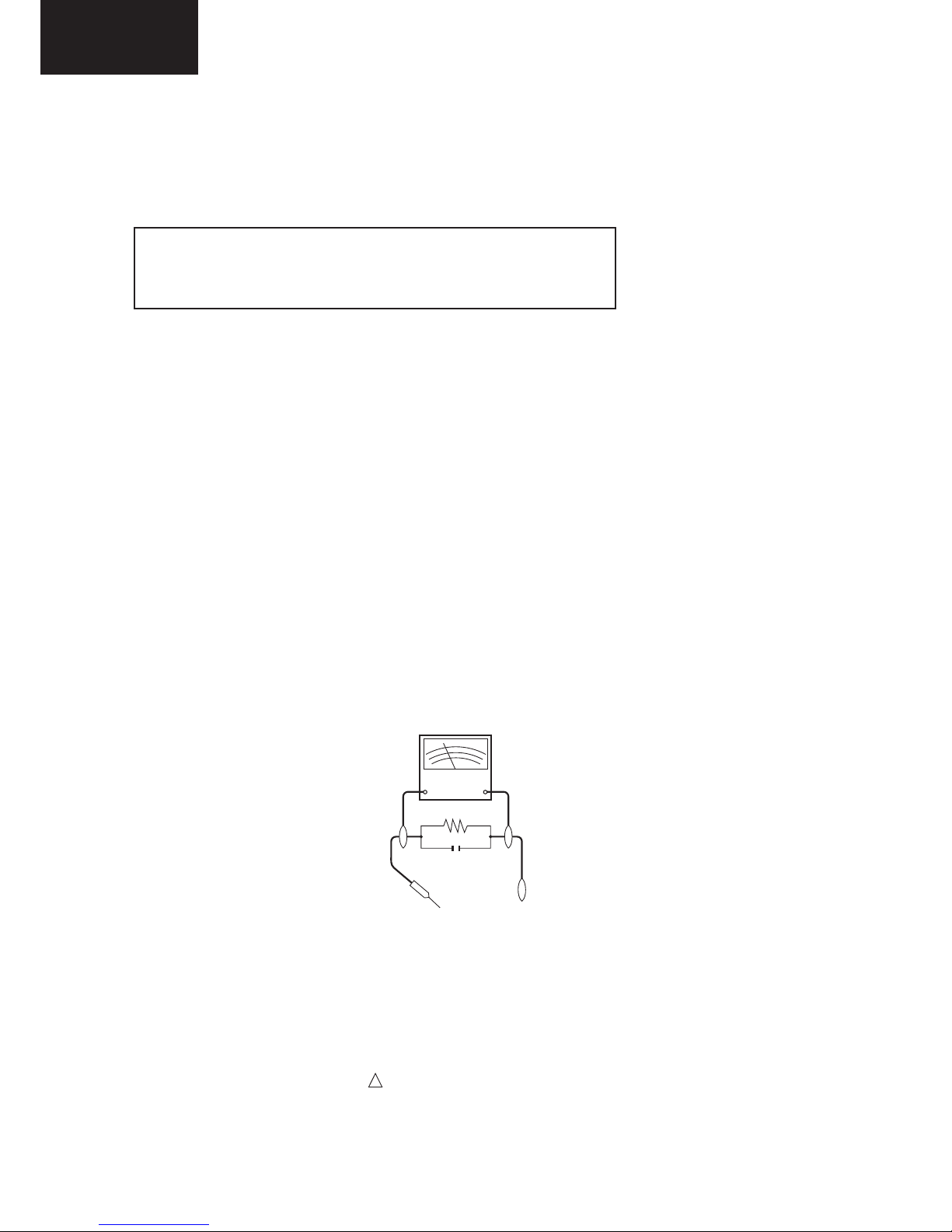
3. To be sure that no shock hazard exists, check for leakage current in the following manner.
• Plug the AC cord directly into a 220~240 volt AC outlet. (Do not use an isolation transformer for this test).
•Using two clip leads, connect a 1.5k ohm, 10 watt resistor paralleled by a 0.15µF capacitor in series with all exposed metal
cabinet parts and a known earth ground, such as electrical conduit or electrical ground connected to an earth ground.
•A true RMS reading multimeter should be used for this test, especially where the equipment uses a switch mode
power supply which may result in very non-sinusoidal leakage current.
•Connect the resistor connection to all exposed metal parts having a return to the chassis (antenna, metal cabinet,
screw heads, knobs and control shafts, escutcheon, etc.) and measure the AC voltage drop across the resistor.
All checks must be repeated with the AC cord plug connection reversed. (If necessary, a nonpolarized adaptor plug must
be used only for the purpose of completing these checks.)
Any reading of 1.05V peak (this corresponds to 0.7 mA. peak AC.) or more is excessive and indicates a potential shock
hazard which must be corrected before returning the monitor to the owner.
!
CAUTION: FOR CONTINUED PROTECTION AGAINST A RISK OF
FIRE REPLACE ONLY WITH SAME TYPE
F100, F101 (T 3.15A L250V)
6
LC-32LE340/343
LC-40LE340/343
LC-32LE340/343
LC-40LE340/343
PRECAUTIONS FOR USING LEAD-FREE SOLDER
1 Using lead-free wire solder
When xing the PWB soldered with the lead-free solder, apply lead-free wire solder. Repairing with conventional lead
wire solder may cause damage or accident due to cracks.
As the melting point of lead-free solder (Sn-Ag-Cu) is higher than the lead wire solder by 40°C, we recommend you to
use a dedicated soldering bit, if you are not familiar with how to obtain lead-free wire solder or soldering bit, contact our
service station or service branch in your area.
2 Soldering
As the melting point of lead-free solder (Sn-Ag-Cu) is about 220°C which is higher than the conventional lead solder by
40°C, and as it has poor solder wettability, you may be apt to keep the soldering bit in contact with the PWB for extended
period of time. However, Since the land may be peeled off or the maximum heat-resistance temperature of parts may be
exceeded, remove the bit from the PWB as soon as you conrm the steady soldering condition.
Lead-free solder contains more tin, and the end of the soldering bit may be easily corroded. Make sure to turn on and
off the power of the bit as required.
If a different type of solder stays on the tip of the soldering bit, it is alloyed with lead-free solder. Clean the bit after every
use of it.
When the tip of the soldering bit is blackened during use, le it with steel wool or ne sandpaper.
Be careful when replacing parts with polarity indication on the PWB silk.
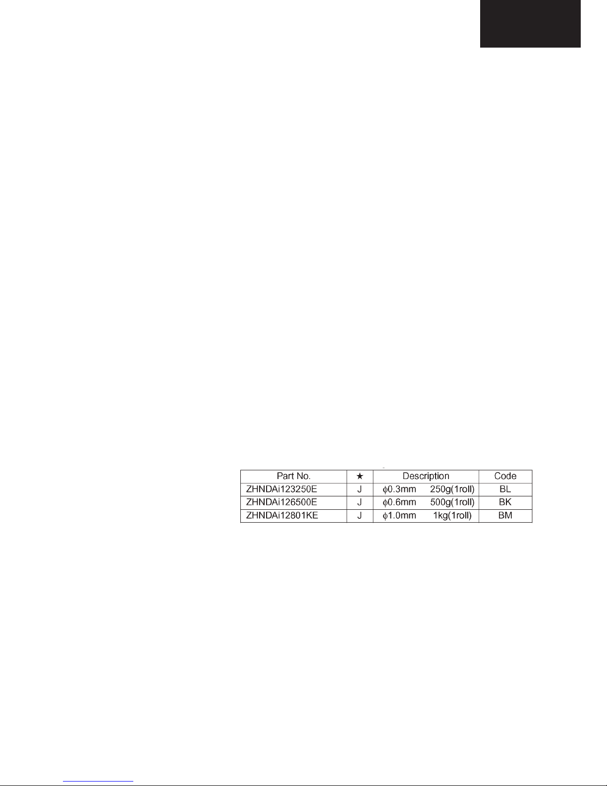
Lead-free wire solder for servicing.
7
LC-32LE340/343
LC-40LE340/343
LC-32LE340/343
LC-40LE340/343
END OF LIFE DISPOSAL
A. Information on Disposal for Users (private households)
1. In the European Union
Attention: If you want to dispose of this equipment, please do not use the ordinary dust bin!
Used electrical and electronic equipment must be treated separately and in accordance with legislation that requires
proper treatment, recovery and recycling of used electrical and electronic equipment.
Following the implementation by member states, private households within the EU states may return their used
electrical and electronic equipment to designated collection facilities free of charge*. In some countries* your local
retailer may also take back your old product free of charge if you purchase a similar new one.
*) Please contact your local authority for further details.
If your used electrical or electronic equipment has batteries or accumulators, please dispose of these separately
beforehand according to local requirements.
By disposing of this product correctly you will help ensure that the waste undergoes the necessary treatment, recovery
and recycling and thus prevent potential negative effects on the environment and human health which could otherwise
arise due to inappropriate waste handling.
2. In other Countries outside the EU
If you wish to discard this product, please contact your local authorities and ask for the correct method of disposal.
For Switzerland: Used electrical or electronic equipment can be returned free of charge to the dealer, even if you don’t
purchase a new product. Further collection facilities are listed on the homepage of www.swico.ch or www.sens.ch.
B. Information on Disposal for Business Users
1. In the European Union
If the product is used for business purposes and you want to discard it:
Please contact your SHARP dealer who will inform you about the take-back of the product. You might be charged for
the costs arising from take-back and recycling. Small products (and small amounts) might be taken back by your local
collection facilities.
For Spain: Please contact the established collection system or your local authority for take-back of your used
products.
2. In other Countries outside the EU
If you wish to discard of this product, please contact your local authorities and ask for the correct method of disposal.
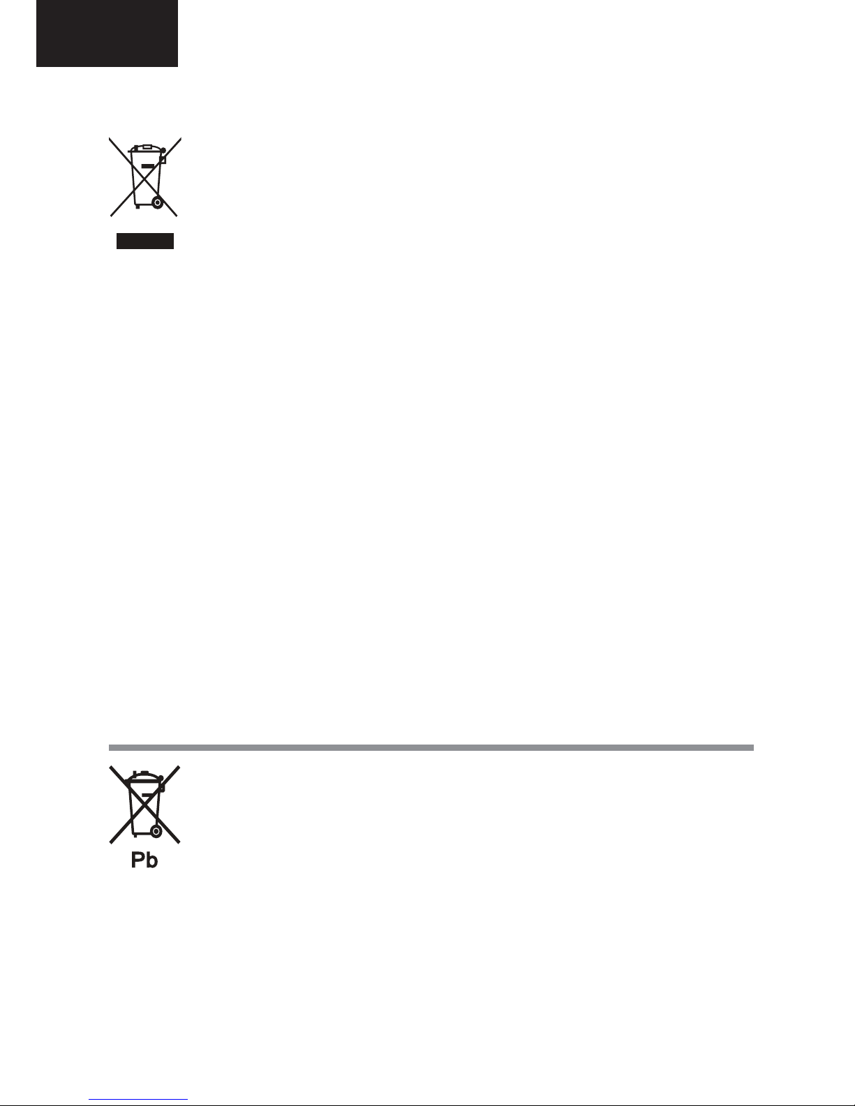
Attention: Your product
is marked with this
symbol. It means that
used electrical and
electronic products
should not be mixed
with general household
waste. There is a
separate collection
system for these
products.
End of life disposal
The battery supplied with this product contains traces of Lead.
For EU: The crossed-out wheeled bin implies that used batteries should not be put to the general household waste!
There is a separate collection system for used batteries, to allow proper treatment and recycling in accordance with
legislation. Please contact your local authority for details on the collection and recycling schemes.
For Switzerland: The used battery is to be returned to the selling point.
For other non-EU countries: Please contact your local authority for correct method of disposal of the used battery.
8
LC-32LE340/343
LC-40LE340/343
LC-32LE340/343
LC-40LE340/343
OPERATION MANUAL
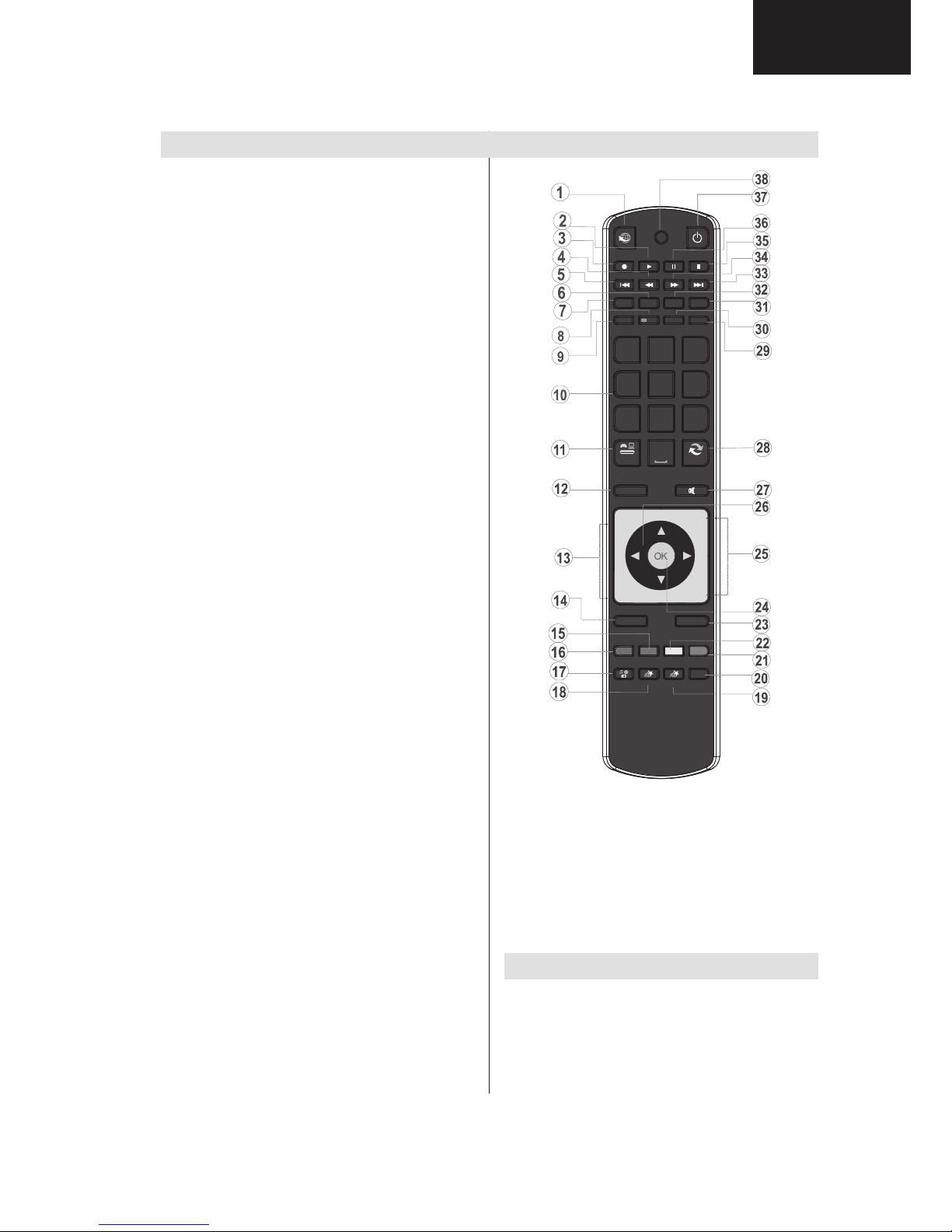
Remote Control Buttons
Acti1. vate Portal mode (*)
Play (in Media Browser mode) 2.
Programme recording3.
Fast rewind (in Media Browser mode)4.
No function5.
Mono/Stereo - Dual I-II / Current Language / 6.
Play preview (in Media Browser mode)
Image size 7.
Teletext / Mix8.
Electronic Programme Guide9.
Numeric buttons10.
AV / Source11.
Menu on/off 12.
Programme Down - Page up / Programme Up - 13.
Page down
Back to previous menu 14.
Green button15.
Red button16.
Media Browser17.
My Button 1: Power save mode on/off18.
My Button 2(**)19.
Info / Reveal (in TXT mode)20.
Blue button21.
Yellow button22.
Exit (in DTV mode) / Return / Index page (in 23.
TXT mode)
OK / Select / Hold (in TXT mode) / Channel List24.
Volume up / down25.
Navigation buttons26.
Mute27.
Previous programme / Now (in EPG mode)28.
Sleep timer29.
Favourite mode selection30.
Picture mode selecion / Changes picture mode 31.
(in Media Browser video mode)
Subtitle on-off / TXT subtitle (analogue TV 32.
mode) / Subtitle (in Media Browser mode).
No function33.
Fast forward (in Media Browser mode)34.
Stop (in Media Browser mode)35.
Pause / Timeshift recording36.
Standby37.
Operation LED light38.
(*) Please refer to Portal TV section to learn
how to use remote control while in portal TV
function.
P -
P +
SOURCE
GHI
PQRS
SCREEN
MENU
EPG
BACK
1
4
7
-
V +
V
SWAP
ABC DEF
JKL MNO
TUV WXYZ
LANG
SUBTITLE
INFO
PRESETS
FAV SLEEP
TEXT
EXIT
2
3
5
6
8
9
0
Y B TN 1M UT O Y B TN 2M UT OMULTIMEDIA
INTERNET
(**)USING MY BUTTON 2
When on a desired source, channel or link, press MY
BUTTON 2 for fi ve seconds, until the “MY BUTTON
IS SET” message is displayed on the screen. This
confirms that MY BUTTON 2 is now associated with
the selected function.
LC32/40LE343 Models (For Italy only.)
18.MHP services
19. ChanneL List
24. OK/ Select / Hold (in TXT mode)
9
LC-32LE340/343
LC-40LE340/343
LC-32LE340/343
LC-40LE340/343
Operation Manual (Continued)
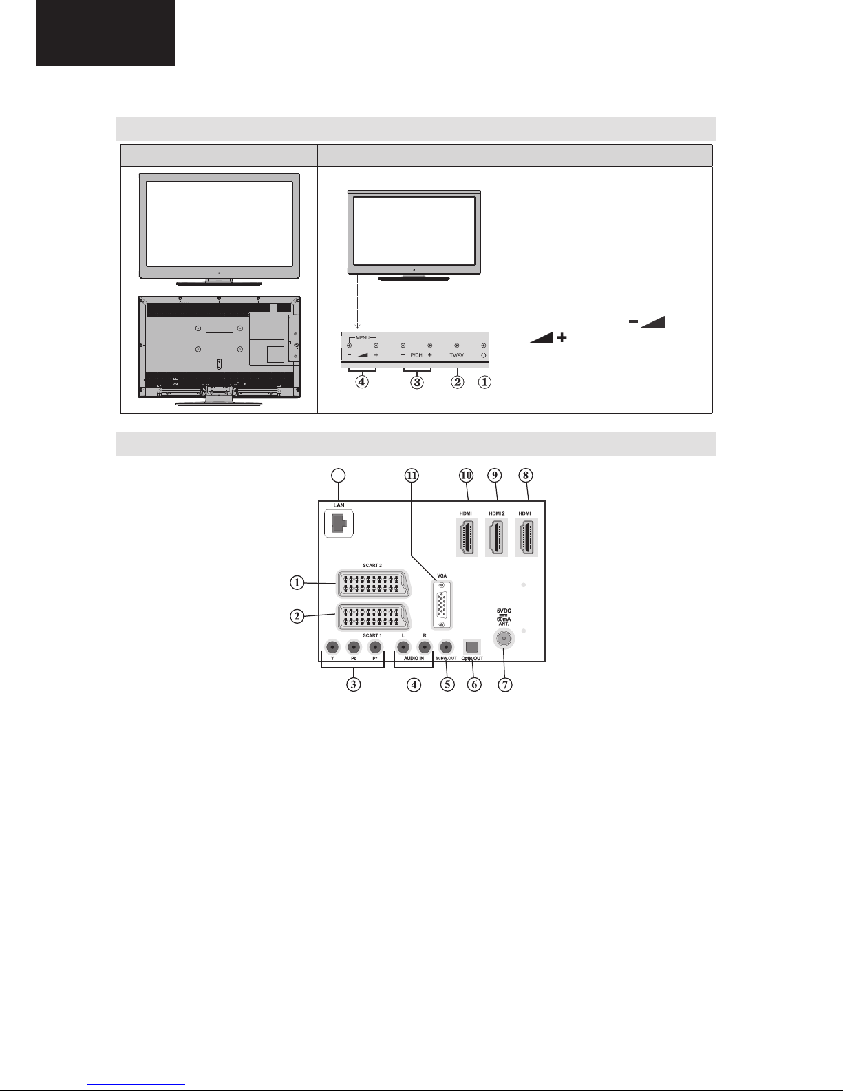
LCD TV and Operating Buttons
FRONT and REAR VIEW Control buttons VIEW Control Buttons
1. Standby/On button
2. TV/AV button
3. Programme Up/Down buttons
4. Volume Up/Down buttons
Note: Press “
” and
“
” buttons at the same
time to view main menu.
Viewing the Back side Connections
12
1 3
SCART 21. inputs or outputs for external devices.
SCART 12. inputs or outputs for external devices. Connect the SCART cable between SCART socket on
the TV and SCART socket on your external device (such as a decoder, a VCR or a DVD player).
Note: If an external device is connected via the SCART socket, the TV will automatically switch to AV
mode.
Component Video Inputs (YPbPr)3. are used for connecting component video.
You can connect the component video and audio sockets with a device that has component output.
Connect the component video cables between the COMPONENT VIDEO INPUTS on on the TV and
the component video outputs of your device. While connecting, be sure that the letters on your TV, “Y”,
“Pb”, “Pr” correspond with your device’s connectors.
PC/YPbPr Audio Inputs4. are used for connecting audio signals of a PC or a device that connects to the
TV via YPbPr. Connect the PC audio cable between the AUDIO INPUTS on the TV and audio output
of your PC to enable PC audio. Connect the audio cable between AUDIO INPUTS on the TV and audio
outputs of your device to enable component audio.
Subwoofer Out5. is for connecting an external, active subwoofer to the set to give a much deeper bass
effect. Use an appropriate RCA cable to connect the set to a subwoofer unit.
S/PDIF Digital Out6. outputs digital audio signals of the currently watched source.
Use a digital optic cable to transfer audio signals to a device that has S/PDIF input.
10
LC-32LE340/343
LC-40LE340/343
LC-32LE340/343
LC-40LE340/343
Operation Manual (Continued)
RF Input7. connects to an aerial or cable antenna system.
Note that if you use a decoder or a media recorder, you should connect the aerial cable through the
device to the television with an appropriate antenna cable, as shown in the illustration in the following
pages.
HDMI 3: HDMI Input8.
HDMI 2: HDMI Input9.
HDMI 1: HDMI Input10.
HDMI Inputs are for connecting a device that has an HDMI socket. Your LCD TV is capable of
displaying High Defi nition pictures from devices such as a High Defi nition Satellite Receiver or DVD
Player. These devices must be connected via the HDMI sockets or Component Socket. These sockets
can accept either 720p or 1080p (optional) signals. No sound connection is needed for an HDMI to
HDMI connection.
PC Input11. is for connecting a personal computer to the TV set.
Connect the PC cable between the PC INPUT on the TV and the PC output on your PC
Ethernet input (for service and Internet connectivity)12.
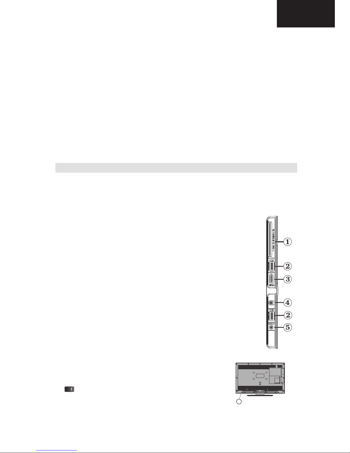
Viewing the Connections - Side Connectors
CI Slot is used for inserting a CI card. A CI card allows you to view all the channels that you subscribe 1.
to. For more information, see “Conditional Access” section.
Side USBs2.
Note that programme recording feature is available via these USB inputs. You can connect external hard disk drives to
this input.
Side HDMI Input is for connecting a device that has an HDMI socket.3.
Headphone jack is used for connecting an external headphone to the system. Connect 4.
to the HEADPHONE jack to listen to the TV from headphones (optional).
Side audio-video connection5. input is used for connecting video and audio signals
of external devices. To make a video connection, you must use the supplied AV
connection cable for enabling connection. First, plug singular jack of the cable to the
TV’s Side AV socket. Afterwards, insert your video cable’s (not supplied) connector into
the YELLOW input (located on the plural side) of the supplied AV connection cable.
Colours of the connected jacks should match.
To enable audio connection, you must use RED and WHITE inputs of the side AV
connection cable. Afterwards, insert your device’s audio cable’s connectors into
the RED and WHITE jack of the supplied side AV connection cable. Colours of the
connected jacks should match.
Note: You should use audio inputs of side AV connection cable (RED & WHITE)
to enable sound connection when connecting a device to your TV by using PC or
COMPONENT VIDEO input.
6. , switch is used for turning the TV on or off.
6
11
LC-32LE340/343
LC-40LE340/343

LC-32LE340/343
LC-40LE340/343
Operation Manual (Continued)
Antenna Connection
Aerial/Cable Connection
Connect the aerial or cable TV plug to the AERIAL •
INPUT socket located at the rear of the TV.
1 3
Aerial or Cable
Power Connection
IMPORTANT: The TV set is designed to operate on
220-240V AC, 50 Hz socket.
After unpacking, allow the TV set to reach the •
ambient room temperature before you connect the
set to the mains. Plug the power cable to the mains
socket outlet.
Using USB Inputs
USB Connection
You can connect a USB hard disk drive or USB •
memory stick to your TV by using the USB inputs
of the TV. This feature allows you to play fi les stored
in a USB drive or record programmes.
2.5” and 3.5” inch (hdd with external power supply) •
external hard disk drives are supported.
To record a programme, you should fi rst connect •
a USB disk to your TV while the TV is switched
off. You should then switch on the TV to enable
recording feature. Otherwise, recording feature will
not be available.
IMPORTANT !
You may back up your fi les before making any •
connections to the TV set in order to avoid any
possible data loss. Note that manufacturer will not
be responsible for any fi le damage or dataloss.
It is possible that certain types of USB devices (e.g. •
MP3 Players) or USB hard disk drives/memory sticks
may not be compatible with this TV.
IMPORTANT: The TV supports only FAT32 and
NTFS disk formatting. However, NTFS format is not
supported for recording features. For recording, if you
connect a USB disk with NTFS format, the TV will ask
you to format the content. See the section, “Format
Disk” in the following pages for more information on
disk formatting.
Note that ALL the data stored on the USB disk will
be lost and then the disk format will be converted to
FAT32 in such a case.
USB Disk Connection
• Plug your USB device to the USB input of the TV.
Note: Plug or unplug your USB disk while the TV is
switched off.
Note: If you are going to connect a USB hard disk drive
to the TV set, USB connection cable used between
the disk drive and the TV should have a USB logo
and should be as short as possible.
Note: While formatting a USB hard disk that has 1TB
(Tera Byte) or more fi le capacity, you can experience
problems with the formatting process. In such a
case, you should format the disk with your personal
computer and the formatted disk type should be
FAT32.
SIDE VIEW USB MEMORY
CAUTION !
Quickly plugging and unplugging USB devices, •
is a very hazardous operation. Especially, do not
repeatedly quickly plug and unplug the drive. This
may cause physical damage to the USB player and
especially the USB device itself.
Do not pull out USB module while playing or •
recording a fi le.
Programme Recording
To record a programme, you should fi rst connect a
USB disk to your TV while the TV is switched off.
You should then switch on the TV to enable recording
feature.
IMPORTANT: When using a new USB hard disk drive,
it is recommended that you fi rst format the disk using
your TV’s “Format Disk” option.
For using recording function, you should connect a •
USB disk or an external hard disk drive to the TV
and connected USB disk should have at least 1 GB
capacity and should have 2.0 speed compatibility.
If the connected USB device does not support 2.0
speed, an error message will be displayed.
Note: Recorded programmes are saved into the
connected USB disk. If desired, you can store/copy
recordings on a computer; however, these fi les will
not be available to be played on a computer. You can
play the recordings only via your TV.
For more information on recording programmes, •
see sections “Instant Recording”, “Timeshifting”,
“Electronic Programme Guide”, “Recordings Library”
or “Recording Timers” in the following parts.
Recorded programmes are split into 4GB •
partitions.
12
LC-32LE340/343
LC-40LE340/343
LC-32LE340/343
LC-40LE340/343
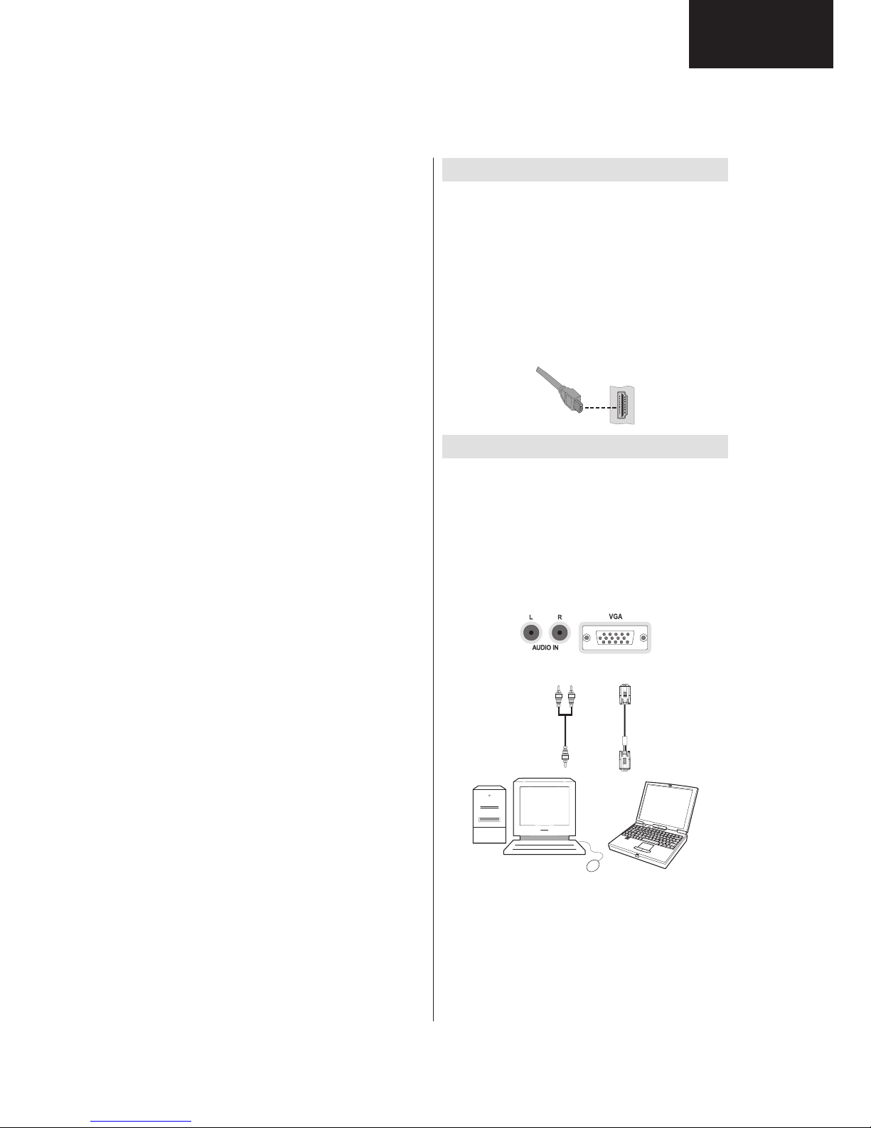
Operation Manual (Continued)
Side HDMI Connection
You can use side HDMI input to connect a device that
has an HDMI connector to your TV. Use an appropriate
HDMI cable to make such a connection. Note that you
should switch to the HDMI source to view the content
from the connected device. Power off both the TV and
the device before making any connections. Side HDMI
Input supports connections between HDMI devices
such as DVD players. You can use side HDMI input
of the TV to connect to an external HDMI device. Use
an HDMI cable to connect.
HDMI DEVICE SIDE VIEW
Connecting the LCD TV to a PC
For displaying your computer’s screen image on your
LCD TV, you can connect your computer to the TV set.
Power off both computer and display before making
any connections. Use 15-pin D-sub display cable to
connect a PC to the LCD TV. When the connection
is made, switch to PC source. See “Input selection”
section. Set the resolution that suits your viewing
requirements. Resolution information can be found
in the appendix parts.
PC audio cable
(not supplied)
PC VGA cable
(not supplied)
Audio inputs of the TV
PC input of the TV
Audio output of the PC
Monitor output of the PC
Recorded programmes are stored in the following •
directory of the connected USB disk: \DVR\RECS.
All recordings are indicated with a number. A text
(txt) fi le is created for each recording. This text
file includes information such as broadcaster,
programme, and recording time.
Timeshifting may be stopped according to USB •
device write speed. If the USB device speed is not
enough for video stream bitrate, timeshifting may
be stopped and recording may fail. If HD service
bitrate is greater than 13 Mbp/sec. some freeze can
be seen during timeshifting on both USB disk and
on external HDD.
Recordings of HD programmes can occupy bigger •
size on the USB disk depending on the broadcast’s
resolution. For this reason it is recommended
to use USB hard disk drives for recording HD
programmes.
Do not plug out the USB/HDD during the recording. •
This may harm the connected USB/HDD.
Multipartiton support is available. Maximum two •
different partitions are supported. If the disk have
more than two partitions, crash may occur. First
partition of the usb disk is used for PVR ready
features. It also must be formatted as primary
partition to be used for PVR ready features.
Some stream packets may not be recorded because •
of signal problems, so sometimes video may freezes
during playback.
Record, Play, Pause, Display (for PlayListDialog) •
keys could not be used when teletext is ON. If a
recording starts from timer when teletext is ON,
teletext is automatically turned off. Also teletext
usage is disabled when there is ongoing recording
or playback.
• Radio record is not supported.
• The Tv can record programmes up to ten hours.
13
LC-32LE340/343
LC-40LE340/343
LC-32LE340/343
LC-40LE340/343
Operation Manual (Continued)
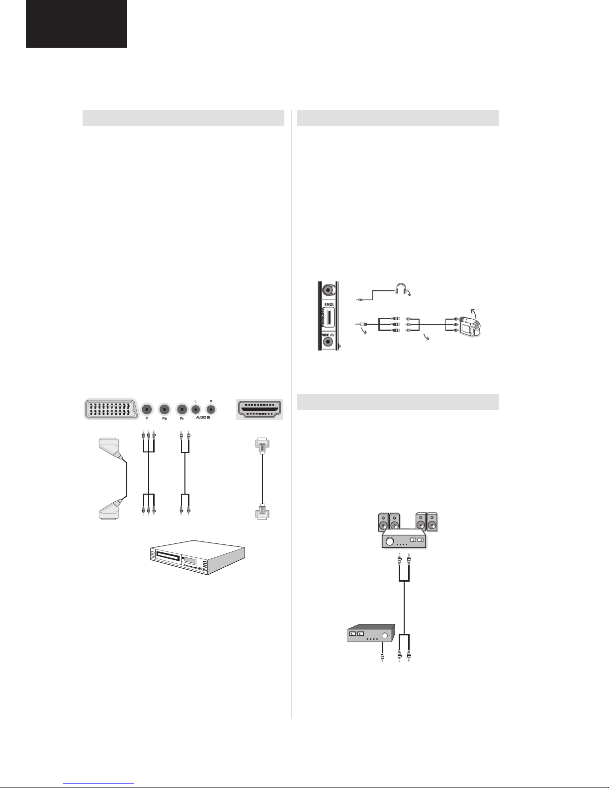
Connecting to a DVD Player
If you want to connect a DVD player to your LCD
TV, you can use connectors of the TV set. DVD
players may have different connectors. Please refer
to your DVD player’s instruction book for additional
information. Power off both the TV and the device
before making any connections.
Note: Cables shown in the illustration are not
supplied.
If your DVD player has an HDMI socket, you can •
connect via HDMI. When you connect to DVD player
as illustrated below, switch to HDMI source. See,
“Input Selection” section.
Most DVD players are connected through •
COMPONENT SOCKETS. Use a component video
cable to connect video input. For enabling audio, use
a component audio cable as illustrated below. When
the connection is made, switch to YPbPr source.
See, “Input selection” section.
You may also connect through the SCART 1 or •
SCART 2. Use a SCART cable as shown below.
Note: These three methods of connection perform the
same function but in different levels of quality. It is not
necessary to connect by all three methods.
HDMI
HDMI
inputs
Scart sockets
Component
video
inputs
Component
audio
inputs
DVD Player
Using Side AV Connectors
You can connect a range of optional equipment to your
LCD TV using side connectors of the TV.
For connecting a camcorder or camera , you should •
use SIDE AV socket (side). To do this, you must use
the supplied video/audio connection cable. First,
plug single jack of the cable to the TV’s AV IN socket
(side). Afterwards, insert your camera cable’s (not
supplied) connectors into the plural part of the video/
audio connection cable. Colours of the connected
jacks should match. See illustration below.
Afterwards, you should switch to • Side AV source. See
the section Input selection in the following sections
for more information.
Camera
AVConnection
Cable(supplied)
AVCable
(notsupplied)
Headphone
To listen the TV sound from headphones, you •
should connect headphones to your TV by using the
HEADPHONE jack as illustrated above.
Using Other Connectors
You can connect a range of optional equipment
to your LCD TV. Possible connections are shown
below. Note that cables shown in the illustration are
not supplied.
For connecting a to a device that has SPDIF support, •
use an appropriate SPDIF cable to enable sound
connection.
External Speakers
A device that
supports
SPDIF signal.
14
LC-32LE340/343
LC-40LE340/343
LC-32LE340/343
LC-40LE340/343
Operation Manual (Continued)
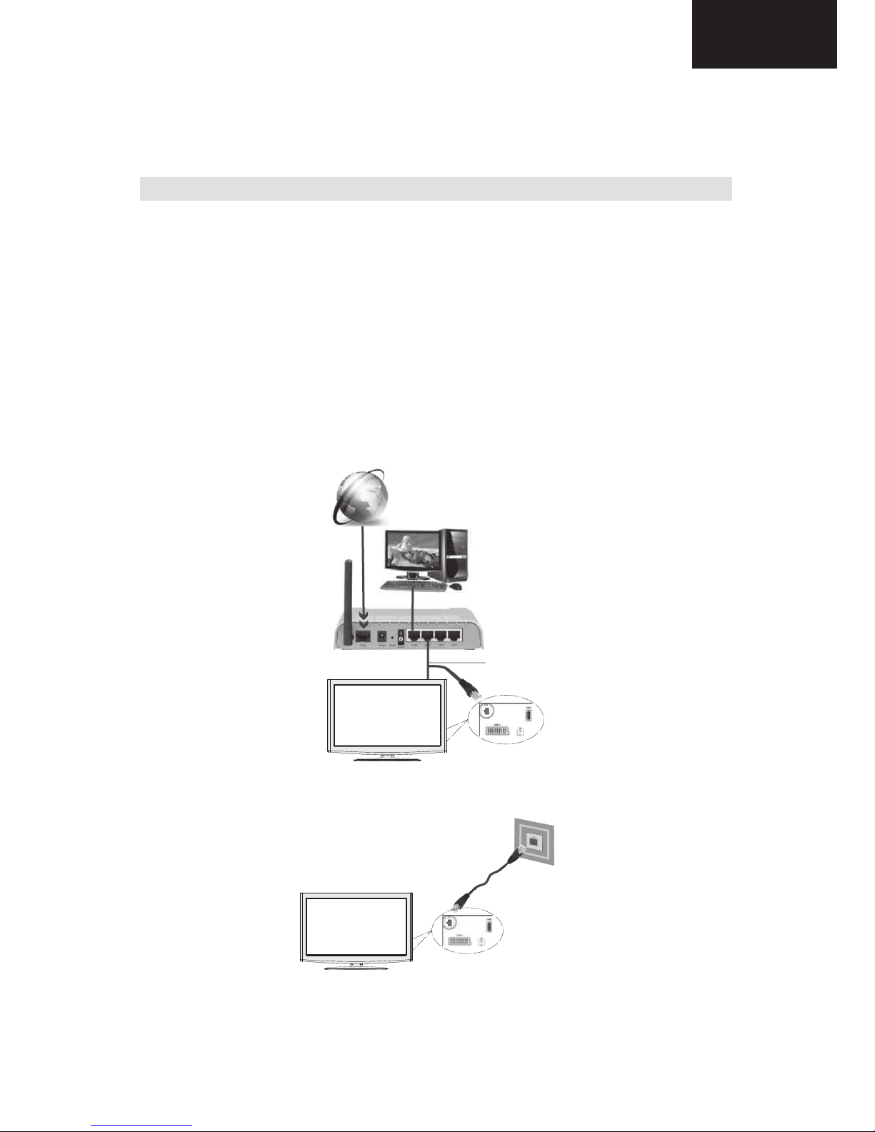
Connecting to a Wired Network
For connecting to a wired LAN network, you should perform the following steps:
Connect broadband ISP connection ethernet cable to the ETHERNET INPUT of your modem.•
Ensure that Nero Media Home software is installed to your PC.(for DLNA function). See Appendix H for more •
information on the installation process.
Afterwards, you should connect your PC to the one of your modem’s LAN connectors (e.g. LAN 1) by using •
a proper LAN cable.
Use another LAN output of your modem (e.g. LAN 2) to enable the connection to your TV. You can add •
your TV to your LAN by connecting the LAN port at the rear of your TV to your modem’s LAN connector as
illustrated below.
To access and play shared fi les, you must Select Media Browser. Press Menu button and select Media •
Browser by using Left or Right button. Press OK to continue. Select the desired fi le type and press OK. You
must always use the Media Browser screen to access and play shared network fi les.
PC/HDD/Media Player or any other devices that are DLNA 1.5 compatible should be used with wired •
connection for higher playback quality.
To confi gure wired settings please refer Network Settings section in Settings menu.
PC with Nero
Media Home
software installed
Lan(Ethernet cable)
Broadband ISP
Connection
Rear of TV
You might be able to connect your TV to your LAN network depending on your network’s confi guration. In •
such a case, use an ethernet cable to connect your TV directly to the network wall outlet.
The modem port
on the wall
Rear of TV
15
LC-32LE340/343
LC-40LE340/343

LC-32LE340/343
LC-40LE340/343
Operation Manual (Continued)
Connecting to a Wireless Network (Optional)
IMPORTANT: “Veezy 100” USB dongle(sold separately) is required to use wireless network feature.
To use your TV with your wireless network, you need a “Veezy 100” Wireless USB dongle. To make your
modem’ s SSID visible, you should change your SSID settings via modem’s software. The TV cannot connect
to the networks with hidden SSID.
For connecting to a wireless LAN network, you should perform the following steps:
Connect broadband ISP connection ethernet cable to the ETHERNET INPUT of your modem.•
Ensure that Nero Media Home software is installed to your PC. (for DLNA function).•
Afterwards, you should connect wireless adaptor to one of the USB inputs of the TV.•
To confi gure wireless settings please refer Network Settings section in Settings menu.
Broadband ISP
Connection
Wireless Lan
Adaptor
PC with Nero
Media Home
software installed
USB Inputs (Side of the TV)
A Wireless-N router (IEEE 802.11a/b/g/n) with simultaneous 2.4 and 5 GHz bands designed to increase •
bandwidth. Optimized for smoother and faster HD video streaming, file transfers, and wireless gaming.
Use LAN connection for quicker file sharing between other devices like computers.•
The frequency and channel differ depending on the area.•
The transmission speed differs depending on the distance and number of obstructions between the •
transmission products, the configuration of these products, the radio wave conditions, the line traffic, and
the products that you use. The transmission may also be cut off or get disconnected depending on the radio
wave conditions DECT phones, or any other WiFi 11b appliances. The standard values of the transmission
speed are the theoretical maximum values for the wireless standards. They are not the actual speeds of
data transmission.
The location where the transmission is most effective differs depending on the usage environment.•
Wireless LAN adaptor should be connected directly to the TV’s USB port. USB hubs are not supported.•
To configure wireless settings please refer wifi section in Settings menu.•
Wireless LAN adaptor supports 802.11 a,b,g & n type modems. It is highly recommended that you should •
use IEEE 802.11n communication protocol in order to avoid any possible problems while watching videos.
Use the other usb input, if you experience problems with audio/video performance.•
You must change your modem’s SSID when there are any other modems around with the same SSID. You •
can encounter connection problems otherwise. Use wired connection instead if you experience problems
with wireless connection.
16
LC-32LE340/343
LC-40LE340/343
LC-32LE340/343
LC-40LE340/343
Operation Manual (Continued)
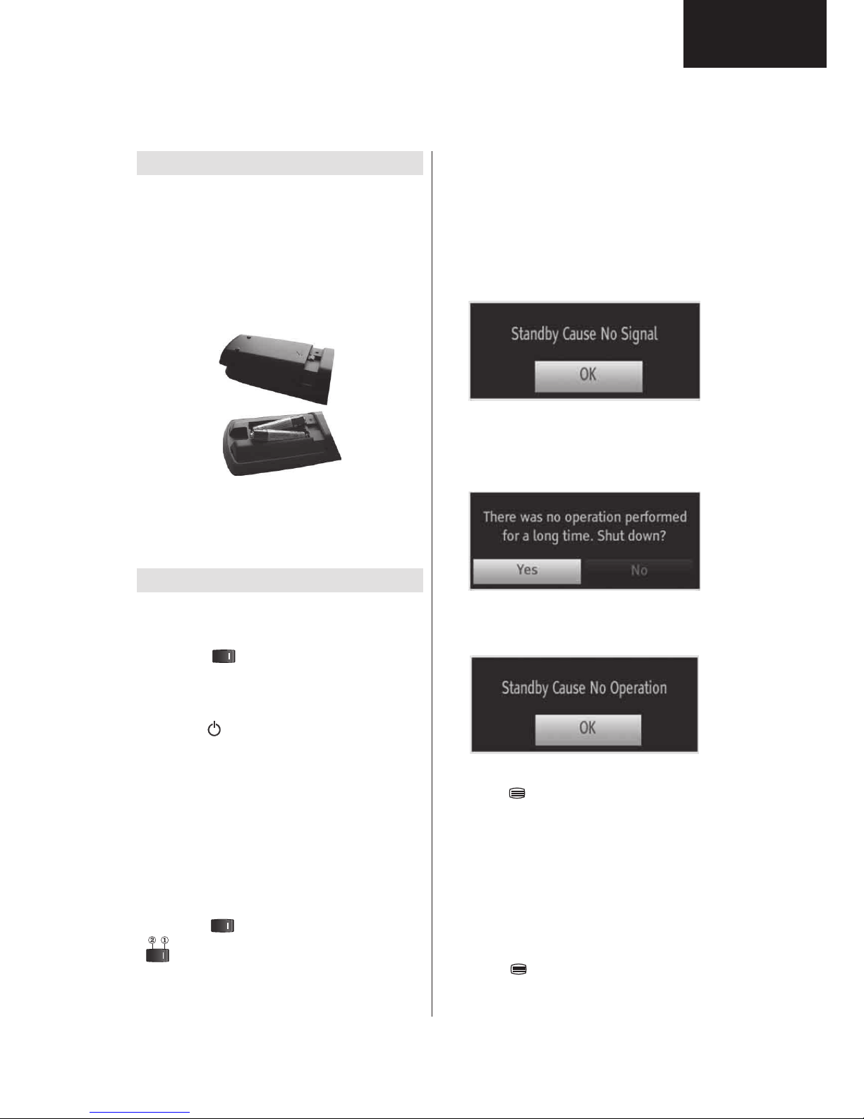
Remote Control Handset
Inserting Batteries
Remove the battery cover located on the back of •
the handset by gently pulling backwards from the
indicated part.
Insert two • AAA/R3 or equivalent type batteries
inside. Insert two AAA/R3 or equivalent type
batteries inside. Observe the correct polarity (+/-)
when inserting batteries and replace the battery
cover.
Note: Remove the battery from remote control
handset when it is not to be used for a long period.
Otherwise it can be damaged due to any leakage of
batteries. Remote range is approximately 7m/23ft.
Switching On/Off
To Switch the TV On
Connect the power cord to the 220-240V AC, 50 •
Hz socket.
Switch the “•
” button on the rear left hand side
to position “|” so the TV will switch to standby mode.
Then the standby LED lights up.
To switch on the TV from standby mode either:•
Press the “•
” button, P+ / P- or a numeric button
on the remote control.
Press the • -P/CH or P/CH+ touch button on the TV.
The TV will then switch on.
Note:
If you switch on your TV via standby button on
the remote control, the programme/source that you were
watching last will be reselected. The TV will switch on with
the last selected channel number, regardless of the channel
number that you select from the remote control to switch
on the TV.
By either method the TV will switch on.
To Switch the TV Off
Switch the “• ” button to position 2 as illustrated,
so the TV will switch OFF.
To power down the TV completely, unplug the •
power cord from the mains socket.
Note: When the TV is switched to standby mode,
standby LED can blink to indicate that features such
as Standby Search, Over Air Download or Timer is
active. The LED can also blink when you switch on
the TV from standby mode.
Standby Notifi cations
If the TV switches off while in No Signal mode, the
following on-screen message will be displayed on the
next switch-on:
When the Auto Tv Off timeout is reached, the following
message will be displayed on the screen. Select YES
to shut down the TV. Select NO to cancel. The TV
will switch off as well, if you do not make a selection
on this screen.
If the TV switches off owing to the auto power down
feature, the following on-screen message will be
displayed on the next switch-on:
Digital Teletext (** for UK only)
• Press the “ ” button.
The digital teletext information appears.•
Operate it with the coloured buttons, cursor buttons •
and OK button.
The operation method may differ depending on the
contents of the digital teletext.
Follow the instructions displayed on digital teletext
screen.
When Press “• OK” button or similar message appears
on the screen, press the OK button.
When the “•
” button is pressed, the TV returns to
television broadcasting.
17
LC-32LE340/343
LC-40LE340/343
LC-32LE340/343
LC-40LE340/343
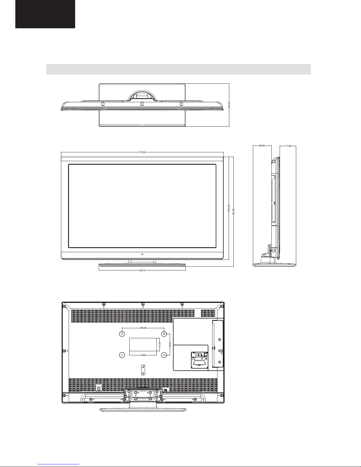
DIMENSIONS
LC-32LE340E/EV/RU LC32LE343E Models
Specifi cations
TV BROADCASTING
PAL/SECAM B/G D/K K’ I/I’ L/L’
RECEIVING CHANNELS
VHF (BAND I/III)
UHF (BAND U)
HYPERBAND
NUMBER OF PRESET CHANNELS
10.000
CHANNEL INDICATOR
On Screen Display
RF AERIAL INPUT
75 Ohm (unbalanced)
OPERATING VOLTAGE
220-240V AC, 50 Hz.
AUDIO OUTPUT POWER (W
RMS.
) (10% THD)
2 x 8
POWER CONSUMPTION (W)
135 W (max)
< 0,5 W (Standby)
PANEL
16:9 display, 32” (80 cm) Screen Size
DIMENSIONS (mm)
DxLxH (With foot): 205,5 x 772,91 x 521,90
Weight (Kg): 10,85
DxLxH (Without foot): 39 x 772,91 x 489,68
Weight (Kg): 9,30
-CVBS analogue output.(In HD channels, this will •
not be available
iii. AUDIO
-MPEG-1 layer I/II, MPEG-2 layer II, AAC, HEAAC, •
AC3, E-AC3
-Sampling frequencies supported are 32, 44.1 & •
48 kHz
Digital Reception (DVB-C)
Transmission Standards:
DVB-C, MPEG2, DVB-C, MPEG4
i. DEMODULATION
-Symbolrate: 4.0 Msymbols/s to 7.2 Msymbols/s
- Modulation: 16-QAM , 32-QAM ,64-QAM, 128-QAM
and 256-QAM
ii. VIDEO
- All MPEG2 MP@ML formats with up-conversion and
fi ltering to CCIR601 format.
-CVBS analogue output
iii. AUDIO
-All MPEG1 Layer 1 and 2 modes
-Sampling frequencies supported are 32, 44.1 & 48
kHz.
Dimensional Drawings
18
LC-32LE340/343
LC-40LE340/343
LC-32LE340/343
LC-40LE340/343
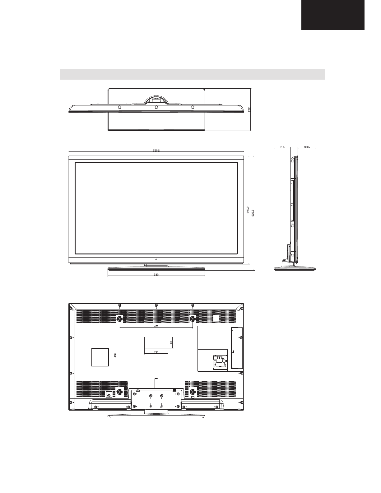
LC-40LE340E/EV/RU LC40LE343E Models
Specifi cations
TV BROADCASTING
PAL/SECAM B/G D/K K’ I/I’ L/L’
RECEIVING CHANNELS
VHF (BAND I/III)
UHF (BAND U)
HYPERBAND
NUMBER OF PRESET CHANNELS
10.000
CHANNEL INDICATOR
On Screen Display
RF AERIAL INPUT
75 Ohm (unbalanced)
OPERATING VOLTAGE
220-240V AC, 50 Hz.
AUDIO OUTPUT POWER (W
RMS.
) (10% THD)
2 x 8
POWER CONSUMPTION (W)
150 W (max)
< 0,5 W (Standby)
PANEL
16:9 display, 40” (102 cm) Screen Size
DIMENSIONS (mm)
DxLxH (With foot): 232 x 959,2 x 626,8
Weight (Kg): 16,75
DxLxH (Without foot): 40 x 959,2 x 592,9
Weight (Kg): 13,90
-CVBS analogue output.(In HD channels, this will •
not be available
iii. AUDIO
-MPEG-1 layer I/II, MPEG-2 layer II, AAC, HEAAC, •
AC3, E-AC3
-Sampling frequencies supported are 32, 44.1 & •
48 kHz
Digital Reception (DVB-C)
Transmission Standards:
DVB-C, MPEG2, DVB-C, MPEG4
i. DEMODULATION
-Symbolrate: 4.0 Msymbols/s to 7.2 Msymbols/s
- Modulation: 16-QAM , 32-QAM ,64-QAM, 128-QAM
and 256-QAM
ii. VIDEO
- All MPEG2 MP@ML formats with up-conversion and
fi ltering to CCIR601 format.
-CVBS analogue output
iii. AUDIO
-All MPEG1 Layer 1 and 2 modes
-Sampling frequencies supported are 32, 44.1 & 48
kHz.
Dimensional Drawings
19
LC-32LE340/343
LC-40LE340/343

LC-32LE340/343
LC-40LE340/343
INTRODUCTION
1. INTRODUCTION
17MB70-2 mainboard is based on Broadcom concept IC. This IC combines DVB-T COFDM
terrestrial and PAL/SECAM demodulators, HDMI receivers, a transport processor, a digital
audio processor, graphics processing, Ethernet MAC and PHY, digital processing of analog
video and audio, analog video digitizer and DAC functions, stereo high-fidelity audio DACs,
a 400-MHz dual-threaded MIP processor, and a peripheral control unit providing a variety of
television control functions. This IC also features an advanced video decoder capable of
supporting high-definition AVC, VC-1, and DVB-T MPEG-2 streams.
Main IC Features:
• Advanced multiformat decoder supporting the following:
- H.264/AVC Main and High Profile to Level 4.1 (HD), Level 3.1 (SD)
- HD/SD AVS Jizhun Profile Levels 2.0, 4.0, and 6.0
- VC-1 Advanced Profile @ Level 3, simple and main profiles
- HD/SD MPEG-2 Main Profile at Main and High levels
- MPEG still image decode
- HD DivX® 3.11/4.11/5.x/6x/Home Theater
• 3D/2D OpenGL® ES 1.0- compliant graphics core
• Integrated Video Processing:
- 3D Color management
- Digital, Analog, and Mosquito Noise Reduction
- 1080i motion adaptive deinterlacing with 3:2/2:2 pull-down
- True 10-bit video carried through system
• Dual HDMI 1.3a receivers
• Extensive audio support:
- AAC+ Level 2, AAC-HE
- Dolby® Digital, Dolby Digital Plus, Trusurround XT®
- MPEG I layers 1, 2, and 3 (MP3)
- Windows Media® and Windows Media Pro audio
- Audio DACs, input switch, and equalizer
• Ethernet MAC and PHY
• Integrated DVB-T COFDM terrestrial demodulator:
- Standards compliance: ETSI EN 300 744, Nordig Unified v1.0.3, DTG D-Book 5
compliant
- Excellent Doppler performance
- Active impulse noise suppression
• Integrated PAL/SECAM Demodulator
• PAL decoder with a 3D/2D comb
• Direct PC input support up to 1600 x 1200 UXGA
• Integrated dual-link LVDS transmitters
• Dual USB 2.0
• A 400-MHz 32-bit MIPS dual CPU with two 32-KB instruction caches
and a combined 64-KB data cache with 128-KB L2 cache
20
LC-32LE340/343
LC-40LE340/343

LC-32LE340/343
LC-40LE340/343
Sound system output is supplying 2x8W (10%THD) for stereo 8speakers
Supported peripherals are:
x 1 RF input VHF I, VHF III, UHF @ 75Ohm(Common)
x 1 Side AV (CVBS, R/L_Audio)
x 2 SCART socket(Common)
x 1 YPbPr (Common)
x 1 Side S-Video(Common)
x 1 PC input(Common)
x 4 HDMI 1.3 input(Common)
x 1 Common interface(Common)
x 1 Optic S/PDIF output(Common)
x 1 Stereo audio input for PC(Common)
x 1 Subwoofer output(Common)
x 1 Headphone(Common)
x 2 USB(Common)
x 1 Bluray/DVD(Optional)
x 1 Ethernet-RJ45 (Common)
x 1 External Touchpad(Common)
21
LC-32LE340/343
LC-40LE340/343
LC-32LE340/343
LC-40LE340/343
2. TUNER
CIRCUIT DESCRIPTIONS
Sound system output is supplying 2x8W (10%THD) for stereo 8speakers
Supported peripherals are:
x 1 RF input VHF I, VHF III, UHF @ 75Ohm(Common)
x 1 Side AV (CVBS, R/L_Audio)
x 2 SCART socket(Common)
x 1 YPbPr (Common)
x 1 Side S-Video(Common)
x 1 PC input(Common)
x 4 HDMI 1.3 input(Common)
x 1 Common interface(Common)
x 1 Optic S/PDIF output(Common)
x 1 Stereo audio input for PC(Common)
x 1 Subwoofer output(Common)
x 1 Headphone(Common)
x 2 USB(Common)
x 1 Bluray/DVD(Optional)
x 1 Ethernet-RJ45 (Common)
x 1 External Touchpad(Common)
2. TUNER
FT 2112/3/8/9 are newly developed Half-NIM modules designed for both digital
(DVB-T / T2 and DTMB for terrestrial China) and analog TV reception in compliance with
the European ATV standards for analogue, as well as with the terrestrial standard ETS 300
744 for DVB-T and the new terrestrial standard ETS 302 755 for DVB-T2. It consists of a 3band RF tuner, which receives RF signal and down-converts it to an IF frequency of 36MHz
for digital and 38.9MHz for analog IF. The analogue IF output can directly drive a SAW
filter. A digital IF Stage, which consists of one SAW filter & gain-controllable IF that offers a
sufficient output level to be connected directly to an A/D converter.
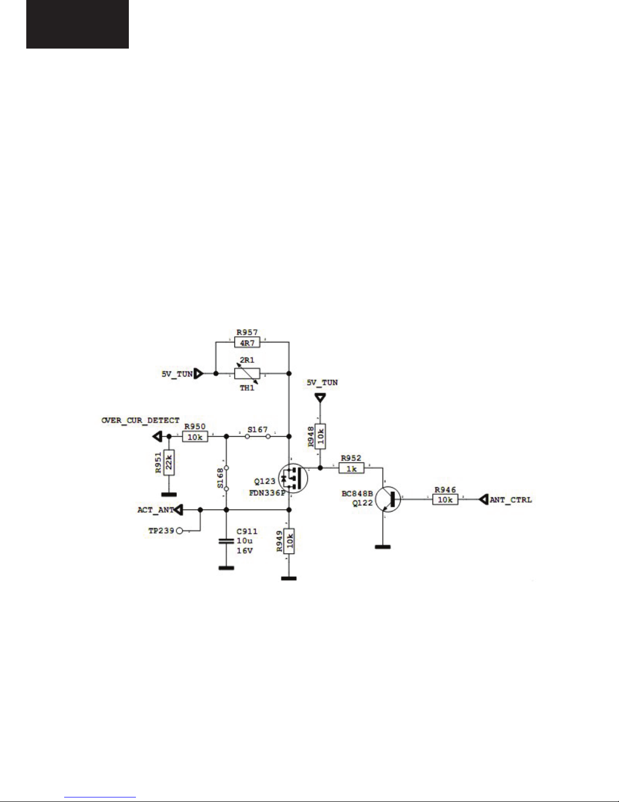
In active antenna option, the following circuit are used. ANT_CTRL pin is controlled by
microcontroller. If ANT_CTRL is low, ANT_PWR will be low. If ANT_CTRL is high,
ANT_PWR will be high. OVER_CUR_DETECT pin is a monitor for short circuit in antenna.
OVER_CUR_DETECT is low, ANT_CTRL will be low, so ANT_PWR will be low. Finally,
short circuit protection is done by circuits and microcontroller.
Active Antenna Circuit
22
LC-32LE340/343
LC-40LE340/343
LC-32LE340/343
LC-40LE340/343
Active Antenna Circuit
1.1. Features of FT2112
• Digital DVB-T T2, DTMB & analogue (48.25MHz to 863.25MHz) reception
• Single 5V supply voltage only
• Built-in 5-33V DC-DC converter
• Single power supply to the RF tuner & IF VGA amplifier section
• Bus Control switch-able RF AGC function:
a) Wide Band AGC for optimum strong signal performance
b) Conventional AGC for optimum analog reception
• RF AGC information via I2C Bus
• Tuner power standby mode via I2C Bus
• Small size (56 mm x 29 mm x 10 mm)
• I2C (SDA & SCL) bus control interface
• ROHS compliant
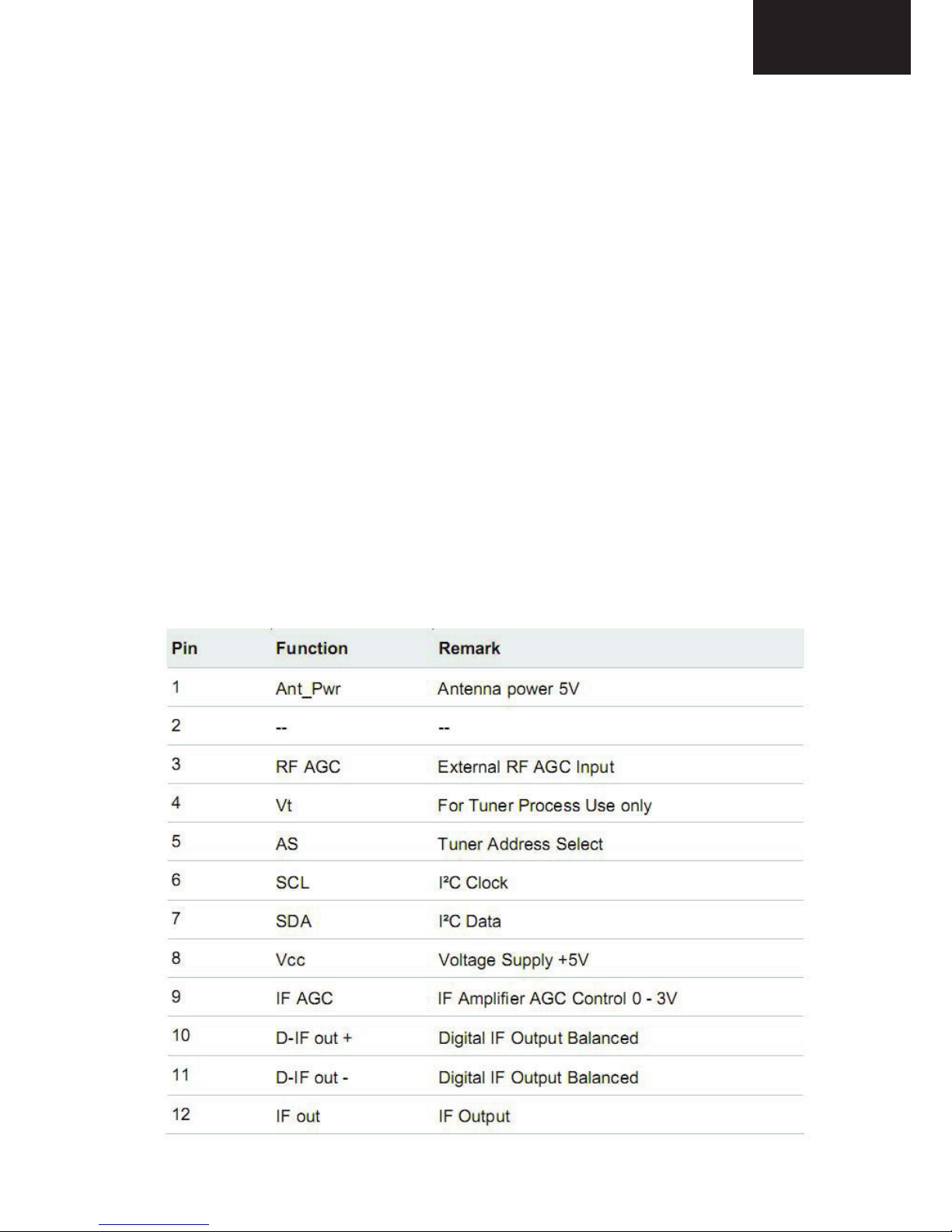
1.2.Tuner Pinning
2.1 Features of FT 2112
2.2 Tuner Pinning
23
LC-32LE340/343
LC-40LE340/343

LC-32LE340/343
LC-40LE340/343
1.2.Tuner Pinning
3. AUDIO AMPLIFIER STAGES
A. MAIN AMPLIFIER (TPA3110)
a. General Description
17MB70 uses TPA 3110 15-W filter-free stereo Class-D audio power amplifier for main
audio output. The TPA3110D2 is a 15-W (per channel) efficient, Class-D audio power
amplifier for driving bridged-tied stereo speakers. Advanced EMI Suppression Technology
enables the use of inexpensive ferrite bead filters at the outputs while meeting EMC
requirements. SpeakerGuard™ speaker protection circuitry includes an adjustable power
limiter and a DC detection circuit. The adjustable power limiter allows the user to set a
"virtual" voltage rail lower than the chip supply to limit the amount of current through the
speaker. The DC detect circuit measures the frequency and amplitude of the PWM signal and
shuts off the output stage if the input capacitors are damaged or shorts exist on the inputs.
The TPA3110D2 can drive stereo speakers as low as 4 7KHKLJKHIILFLHQFy of the
TPA3110D2, 90%, eliminates the need for an external heat sink when playing music. The
outputs are also fully protected against shorts to GND, VCC, and output-to-output. The shortcircuit protection and thermal protection includes an auto-recovery feature.
b. Features
• 15-W/ch into an 8-/RDGVDW7+'1)URPD-V Supply
• 10-W/ch into 8-/RDGVDW7+'1)URPD 13-V Supply
• 30-W into a 4-0RQR/RDGDW7+'1)URPD-V Supply
• 90% Efficient Class-D Operation Eliminates Need for Heat Sinks
• Wide Supply Voltage Range Allows Operation from 8 V to 26 V
• Filter-Free Operation
• SpeakerGuard™ Speaker Protection Includes Adjustable Power Limiter plus DC Protection
• Flow Through Pin Out Facilitates Easy Board Layout
• Robust Pin-to-Pin Short Circuit Protection and Thermal Protection with Auto Recovery
Option
• Excellent THD+N / Pop-Free Performance
• Four Selectable, Fixed Gain Settings
• Differential Inputs
24
LC-32LE340/343
LC-40LE340/343
LC-32LE340/343
LC-40LE340/343
The TPA3110D2 can drive stereo speakers as low as 4 7KHKLJKHIILFLHQFy of the
TPA3110D2, 90%, eliminates the need for an external heat sink when playing music. The
outputs are also fully protected against shorts to GND, VCC, and output-to-output. The short-
circuit protection and thermal protection includes an auto-recovery feature.
b. Features
• 15-W/ch into an 8-/RDGVDW7+'1)URPD-V Supply
• 10-W/ch into 8-/RDGVDW7+'1)URPD 13-V Supply
• 30-W into a 4-0RQR/RDGDW7+'1)URPD-V Supply
• 90% Efficient Class-D Operation Eliminates Need for Heat Sinks
• Wide Supply Voltage Range Allows Operation from 8 V to 26 V
• Filter-Free Operation
• SpeakerGuard™ Speaker Protection Includes Adjustable Power Limiter plus DC Protection
• Flow Through Pin Out Facilitates Easy Board Layout
• Robust Pin-to-Pin Short Circuit Protection and Thermal Protection with Auto Recovery
Option
• Excellent THD+N / Pop-Free Performance
• Four Selectable, Fixed Gain Settings
• Differential Inputs
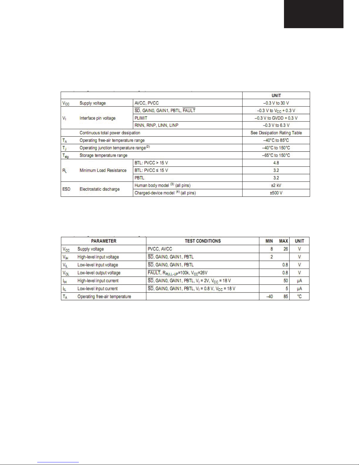
c. Absolute Ratings
d. Recommended Operating Conditions
25
LC-32LE340/343
LC-40LE340/343
LC-32LE340/343
LC-40LE340/343
d. Recommended Operating Conditions
e. Pin Functions
.
PIN
I/O/P DESCRIPTION
Pin
NAME
Number
Shutdown logic input for audio amp (LOW = outputs Hi-Z, HIGH = outputs
SD
1 I
enabled). TTL logic levels with compliance to AVCC.
Open drain output used to display short circuit or dc detect fault status. Voltage
compliant to AVCC. Short circuit faults can be set to auto-recovery by connecting
FAULT
2 O
FAULT pin to SD pin. Otherwise, both short circuit faults and dc detect faults must
be reset by
cycling
PVCC.
LINP 3 I
Positive audio input for left channel. Biased at 3V.
LINN 4 I Negative audio input for left channel. Biased at 3V.
GAIN0 5 I
Gain select least significant bit. TTL logic levels with compliance to AVCC.
GAIN1 6 I
Gain select most significant bit. TTL logic levels with compliance to AVCC.
AVCC 7 P
Analog supply
AGND 8 Analog signal ground. Connect to the thermal pad.
High-side
FET gate drive supply. Nominal voltage is 7V. Also should be used as
GVDD
9 O
supply for PLIMIT function
Power limit level adjust. Connect a resistor divider from GVDD to GND to set
PLIMIT 10 I
power limit. Connect directly to GVDD for no power limit.
RINN 11 I
Negative audio input for right channel. Biased at 3V.
RINP 12 I
Positive audio input for right channel. Biased at 3V.
NC 13
Not connected
PBTL 14 I
Parallel BTL mode switch
Power supply for right channel H-bridge. Right channel and left channel power
PVCCR 15 P
supply inputs are connect internally.
Power supply for right channel H-bridge. Right channel and left channel power
PVCCR 16 P
supply inputs are connect internally.
BSPR 17 I
Bootstrap I/O for right channel, positive high-side FET.
OUTPR 18 O
Class-D H-bridge positive output for right channel.
PGND 19 Power ground for the H-bridges.
OUTNR 20 O
Class-D H-bridge negative output for right channel.
BSNR 21 I
Bootstrap I/O for right channel, negative high-side FET.
BSNL 22 I
Bootstrap I/O for left channel, negative high-side FET.
OUTNL 23 O
Class-D H-bridge negative output for left channel.
PGND 24
Power ground for the H-bridges.
OUTPL 25 O
Class-D H-bridge positive output for left channel.
BSPL 26 I
Bootstrap I/O for left channel, positive high-side FET.
Power supply for left channel H-bridge. Right channel and left channel power
PVCCL 27 P
supply inputs are connect internally.
Power supply for left channel H-bridge. Right channel and
left channel power
PVCCL 28 P
supply inputs are connect internally.
26
LC-32LE340/343
LC-40LE340/343
LC-32LE340/343
LC-40LE340/343
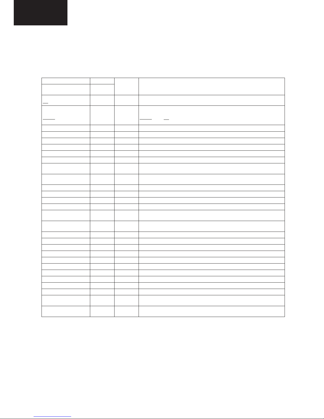
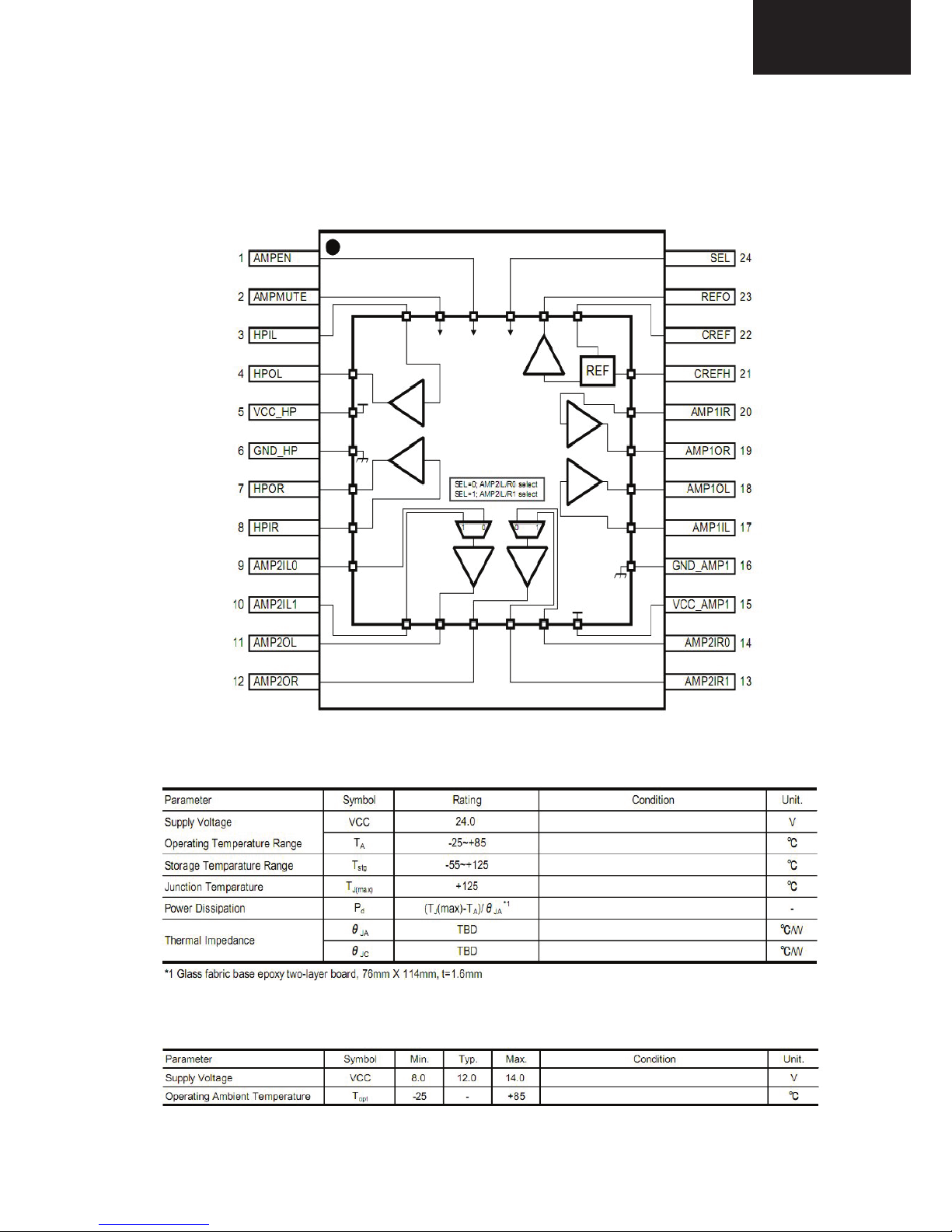
B. LINE-OUT and HEAD-PHONE AMPLIFIER STAGE (CXA3813N)
a. Functional Block Diagram
b. Absolute Ratings
c. Recommended Operating Conditions
27
LC-32LE340/343
LC-40LE340/343
LC-32LE340/343
LC-40LE340/343
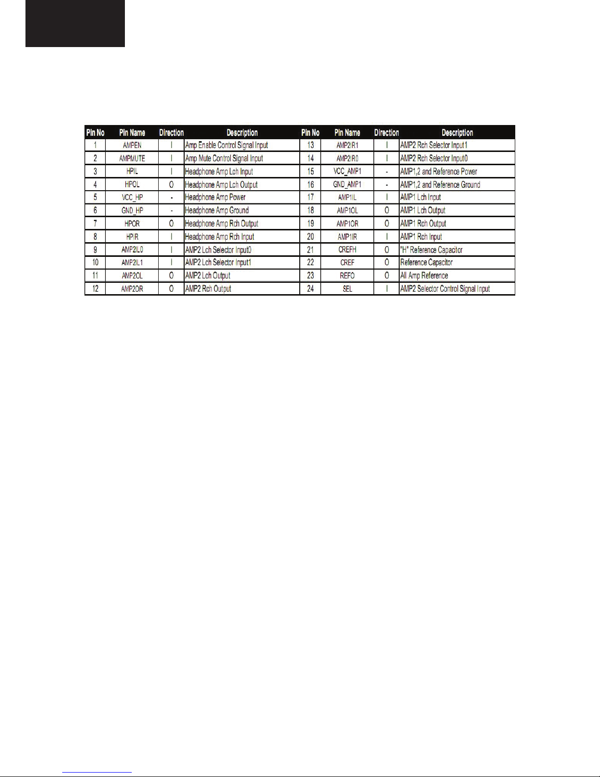
d. Pin Functions
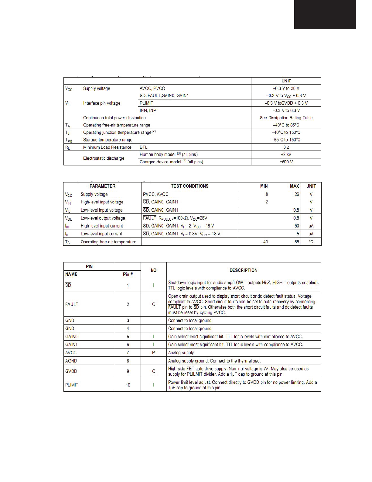
C. SUBWOOFER AMPLIFIER STAGE (TPA3112)
a. General Description
The TPA3112D1 is a 25-W efficient, Class-D audio power amplifier for driving a bridge tied
speaker. Advanced EMI Suppression Technology enables the use of inexpensive ferrite bead
filters at the outputs while meeting EMC requirements. SpeakerGuard speaker protection
system includes an adjustable power limiter and a DC detection circuit. The adjustable power
limiter allows the user to set a "virtual" voltage rail lower than the chip supply to limit the
amount of current through the speaker. The DC detect circuit measures the frequency and
amplitude of the PWM signal and shuts off the output stage if the input capacitors are
damaged or shorts exist on the inputs. The TPA3112D1 can drive a mono speaker as low as
47KHKLJKHIILFLHQF\RIWKH73$'! eliminates the need for an external heat
sink when playing music. The outputs are fully protected against shorts to GND, VCC, and
output-to-output. The short-circuit protection and thermal protection includes an autorecovery feature.
b. Features
• 25-W into an 8-/RDGDW7+'1)URPD96XSSO\
• 20-W into an 4-/RDGat 10% THD+N From a12-V Supply
• 94% Efficient Class-D Operation into 8-/RDG(OLPLQDWHV1HHGIRU+HDW6LQNV
• Wide Supply Voltage Range Allows Operationfrom 8 to 26 V
• Filter-Free Operation
• SpeakerGuard™ Speaker Protection IncludesAdjustable Power Limiter plus DC Protection
• Flow Through Pin Out Facilitates Easy BoardLayout
• Robust Pin-to-Pin Short Circuit Protection andThermal Protection with Auto-Recovery
Option
• Excellent THD+N/ Pop Free Performance
• Four Selectable, Fixed Gain Settings
• Differential Inputs
28
LC-32LE340/343
LC-40LE340/343
LC-32LE340/343
LC-40LE340/343
c. Absolute Ratings
d. Recommended Operating Conditions
e. Pin Functions
29
LC-32LE340/343
LC-40LE340/343
LC-32LE340/343
LC-40LE340/343
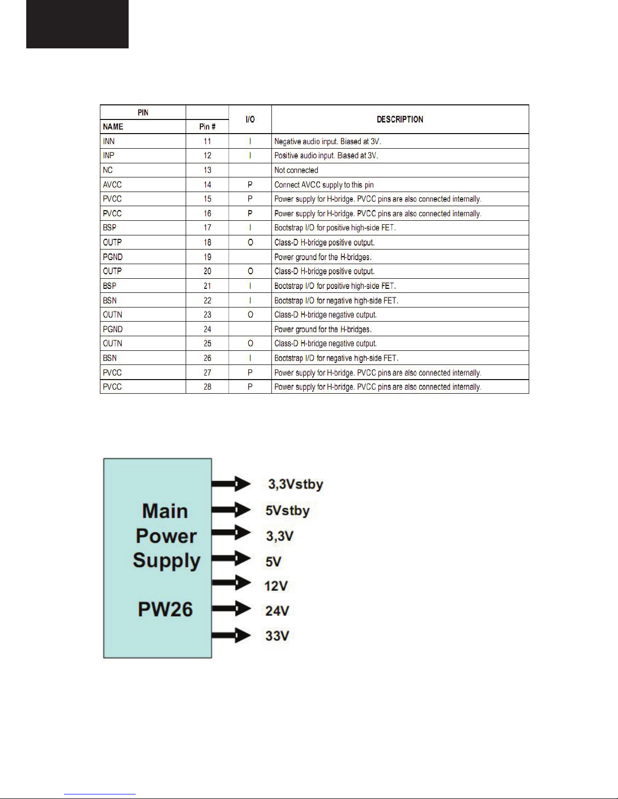
4. POWER STAGE
17MB70 general power managment
block diagram is shown below.
17PW26 power board is used in 32”
17MB70 TV sets.
3,3V stby, 5V stby, 3,3V, 5V, 12V,
24V and 33V can be generated by
PW26.
Below blocks are generated by stepdowns and regulators on MB70
board.
30
LC-32LE340/343
LC-40LE340/343
 Loading...