


LC-32LB261U
32″&42″&50″LCD TV Best Buy LC-32LB261U- LC-42LB261U- LC-50LB261U
1
Service
Service
Service
TABLE OF CONTENTS
Description Page Description Page
SAFETY NOTICE
ANY PERSON ATTEMPTING TO SERVICE THIS CHASSIS MUST FAMILIARIZE HIMSELF WITH THE CHASSIS
AND BE AWARE OF THE NECESSARY SAFETY PRECAUTIONS TO BE USED WHEN SERVICING
ELECTRONIC EQUIPMENT CONTAINING HIGH VOLTAGES.
CAUTION: USE A SEPARATE ISOLATION TRANSFOMER FOR THIS UNIT WHEN SERVICING
7. Adjustment..............................................................34
7.1 ADC and W/B Adjustment………………..…….34
7.2 F/W upgrade……………………..……………........35
7.3 DDC upgrade…………………..……………........36
8. Block Diagram.…….................................................37
9. Schematic……………...…………..……..…………...39
9.1 Main Board…………………………………...….......39
9.2 Power Board…………….…………...…………......53
9.3 Key Board……………….……………………….......63
9.4 IR Board………………………………..….…….......64
10. LOCATION Waveform and Voltage…………..….65
11. Exploded View……………………………….….…...68
12. BOM List……………….……………………………77
Table Of Contents.......……..............................………......1
Important Safety Notice.......................................……......2
Revision List…………………………………………………3
1. General Specification..............................………...........4
2. Operating Instructions…………………….……...….......5
3. Input/Output Specification…………....................…....6
4. Mechanical Instructions…………………….................9
5. Repair Flow Chart.……………………….…….…….....18
6. PCB Layout.………………..……………….....….........25
6.1 Main Board…………..……………...………...............25
6.2 Power Board……………..………….……….….......27
6.3 Key Board………………………..………………......33
6.4 IR Board…………………………..……………........33

32″&42″&50″LCD TV Best Buy LC-32LB261U- LC-42LB261U- LC-50LB261U
2
Important Safety Notice
Proper service and repair is important to the safe, reliable operation of all AOC Company Equipment. The service
procedures recommended by AOC and described in this service manual are effective methods of performing service
operations. Some of these service operations require the use of tools specially designed for the purpose. The
special tools should be used when and as recommended.
It is important to note that this manual contains various CAUTIONS and NOTICES which should be carefully read in
order to minimize the risk of personal injury to service personnel. The possibility exists that improper service
methods may damage the equipment. It is also important to understand that these CAUTIONS and NOTICES ARE
NOT EXHAUSTIVE. AOC could not possibly know, evaluate and advise the service trade of all conceivable ways in
which service might be done or of the possible hazardous consequences of each way. Consequently, AOC has not
undertaken any such broad evaluation. Accordingly, a servicer who uses a service procedure or tool which is not
recommended by AOC must first satisfy himself thoroughly that neither his safety nor the safe operation of the
equipment will be jeopardized by the service method selected.
Hereafter throughout this manual, AOC Company will be referred to as AOC.
WARNING
Use of substitute replacement parts, which do not have the same, specified safety characteristics, might create
shock, fire, or other hazards.
Under no circumstances should the original design be modified or altered without written permission from AOC.
AOC assumes no liability, express or implied, arising out of any unauthorized modification of design.
Servicer assumes all liability.
FOR PRODUCTS CONTAINING LASER:
DANGER-Invisible laser radiations when open AVOID DIRECT EXPOSURE TO BEAM.
CAUTION-Use of controls or adjustments or performance of procedures other than those specified herein may
result in hazardous radiation exposure.
CAUTION -The use of optical instruments with this product will increase eye hazard.
TO ENSURE THE CONTINUED RELIABILITY OF THIS PRODUCT, USE ONLY ORIGINAL MANUFACTURER'S
REPLACEMENT PARTS, WHICH ARE LISTED WITH THEIR PART NUMBERS IN THE PARTS LIST SECTION OF
THIS SERVICE MANUAL.
Take care during handling the LCD module with backlight unit
-Must mount the module using mounting holes arranged in four corners.
-Do not press on the panel, edge of the frame strongly or electric shock as this will result in damage to the screen.
-Do not scratch or press on the panel with any sharp objects, such as pencil or pen as this may result in damage to
the panel.
-Protect the module from the ESD as it may damage the electronic circuit (C-MOS).
-Make certain that treatment person’s body is grounded through wristband.
-Do not leave the module in high temperature and in areas of high humidity for a long time.
-Avoid contact with water as it may a short circuit within the module.
-If the surface of panel becomes dirty, please wipe it off with a soft material. (Cleaning with a dirty or rough cloth may
damage the panel.)

32″&42″&50″LCD TV Best Buy LC-32LB261U- LC-42LB261U- LC-50LB261U
3
Revision List
Version Release Date Revision Instructions Customer Model TPV Model
A00 May.30.2014 Initial Release
LC-32LB261U E32E41NKFMBSNNX
LC-42LB261U E42E41NKFMBSNNX
LC-50LB261U E50E41NKFMBSNNX
A01 Jun.13.2014 Add New Model LC-32LB261U E32E51NKFMBSNNX
A02 Jul. 22.2014 Add New Model
LC-32LB261U E32E41NKFMBPNNX
LC-42LB261U E42E41NKFMBPNNX
LC-50LB261U E50E41NKFMBPNNX
A03 Oct. 30.2014 Add New Model
LC-32LB261U
E32E41NKFMBRNNX
E32E51NKFMBRNNX
LC-42LB261U E42E41NKFMBRNNX
LC-50LB261U E50E41NKFMBRNNX

32″&42″&50″LCD TV Best Buy LC-32LB261U- LC-42LB261U- LC-50LB261U
4
1. General Specification
Please refer to user manual.

32″&42″&50″LCD TV Best Buy LC-32LB261U- LC-42LB261U- LC-50LB261U
5
2. Operating Instructions
Please refer to user manual.
32″&42″&50″LCD TV Best Buy LC-32LB261U- LC-42LB261U- LC-50LB261U
6
3. Input/output Specification
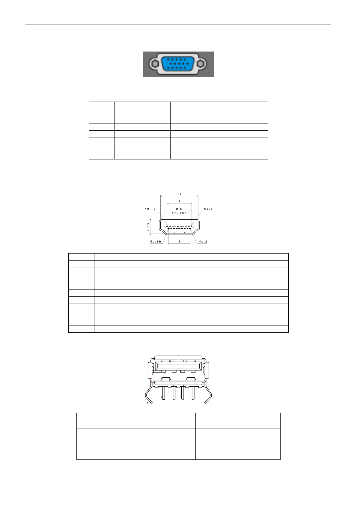
3.1 RGB Signal Input
15 - Pin Color Display Signal Cable
1 Red Video 9 VGA 5V
2 Green Video 10 Sync Ground
3 Blue Video 11 Uart RX
4 Uart TX 12 Serial Data for DDC
5 Ground 13 H-Sync.
6 Red Ground 14 V-Sync.
7 Green Ground 15 Serial Clock for DDC
8 Blue Ground
3.2 HDMI Digital connector pin assignments
PIN Signal Assignment PIN Signal Assignment
1 TMDS Data2+ 2 TMDS Data2 Shield
3 TMDS Data2- 4 TMDS Data1+
5 TMDS Data1 Shield 6 TMDS Data1-
7 TMDS Data0+ 8 TMDS Data0 Shield
9 TMDS Data0- 10 TMDS Clock+
11 TMDS Clock Shield 12 TMDS Clock-
13 CEC 14 NC
15 SCL 16 SDA
17 DDC/CEC Ground 18 +5V Power
19 Hot Plug Detect
3.3 USB
PIN Signal Assignment PIN Signal Assignment
1 VCC 2 Data-
3 Data+ 4 GND
32″&42″&50″LCD TV Best Buy LC-32LB261U- LC-42LB261U- LC-50LB261U
7
3.4 AV Signal Performance
3.4.1 Video / Component Video Input
All tests must be performed under “video standard testing conditions” unless otherwise specified
3.4.2 AV (Composite Video Input)
Video
System NTSC
Amplitude 1.0 V (p-p), negative sync.
Impedance 75 ohm terminated
3.4.3 Component (Y, Pb/Cb, Pr/Cr Input)
Component
System 480i, 480P, 720P, 1080i, 1080P
Y signal amplitude 1.0Vpp (including sync)
Cr, (R-Y) / Cb, (B-Y)
Signal amplitude
±0.35Vpp, 75 ohm
Impedance
75 ohm terminated
Y = 0.299R + 0.587G + 0.114B
(R-Y) = 0.701R + 0.587G + 0.114B
(B-Y) = 0.299R + 0.587G + 0.886B
3.5 Compatible Mode Table
Analog RGB Input Signal Timing
Supported
Resolution
H(KHZ) V(HZ) Standard EDID Assignment
Panel Type
NOTE2
H×V
1366X768 1920X1080
640×480
31.5 60 VESA DMT
Established Timings
YES YES
720×400
31.5 70 VESA DMT
Established Timings
YES
YES
800×600
37.9 60 VESA DMT
Established Timings
YES
YES
800×600
35.1 56 VESA
Established Timings
YES
YES
1024×768
48.4 60 VESA DMT
Established Timings
YES
YES
1280×768
47.4 60 VESA DMT
Detailed Timing
Description 2
YES
YES NOTE3
1280×720
45 60 VESA DMT
Standard Timing
Identification
YES
YES 16:9
1280×800
49.7 60 VESA DMT
Standard Timing
Identification
YES
YES 16:10
1280×800
62.8 75 VESA DMT
Standard Timing
Identification
YES
YES
16:10
Mandatory
1280×960
60 60 VESA DMT
Standard Timing
Identification
YES
YES 4:3
1280×1024
64 60 VESA DMT
Standard Timing
Identification
YES
YES 5:4
1440×900
55.9 60 VESA DMT
Standard Timing
Identification
YES
YES 16:10
1680×1050
65.3 60 VESA DMT
Standard Timing
Identification
NOTE1
YES
16:10
Mandatory
1920×1080
67.5 60 CEA-861
Detailed Timing
Description 1
NO
YES NOTE3
32″&42″&50″LCD TV Best Buy LC-32LB261U- LC-42LB261U- LC-50LB261U
8
HDMI Input Signal Timing:
Supported
Resolution
H(KHZ) V(HZ) Standard
EDID
Assignment
Panel Type
NOTE2
H×V
1366X768 1920X1080
640×480
31.5 60 VESA DMT
Established
Timings
YES
YES
720×400
31.5 70 VESA DMT
Established
Timings
YES
YES
800×600
37.9 60 VESA DMT
Established
Timings
YES
YES
800×600
35.1 56 VESA
Established
Timings
YES
YES
1024×768
48.4 60 VESA DMT
Established
Timings
YES
YES
1280×768
47.4 60 VESA DMT
Detailed Timing
Description 2
YES
YES NOTE3
1280×720
45 60 VESA DMT
Standard Timing
Identification
YES
YES 16:9
1280×800
49.7 60 VESA DMT
Standard Timing
Identification
YES
YES 16:10
1280×800
62.8 75 VESA DMT
Standard Timing
Identification
YES
YES
16:10
Mandatory
1280×960
60 60 VESA DMT
Standard Timing
Identification
YES
YES 4:3
1280×1024
64 60 VESA DMT
Standard Timing
Identification
YES
YES 5:4
1440×900
55.9 60 VESA DMT
Standard Timing
Identification
YES
YES 16:10
1680×1050
65.3 60 VESA DMT
Standard Timing
Identification
NOTE1
YES
16:10
Mandatory
1920×1080
67.5 60 CEA-861
Detailed Timing
Description 1
YES
YES NOTE3
32″&42″&50″LCD TV Best Buy LC-32LB261U- LC-42LB261U- LC-50LB261U
9
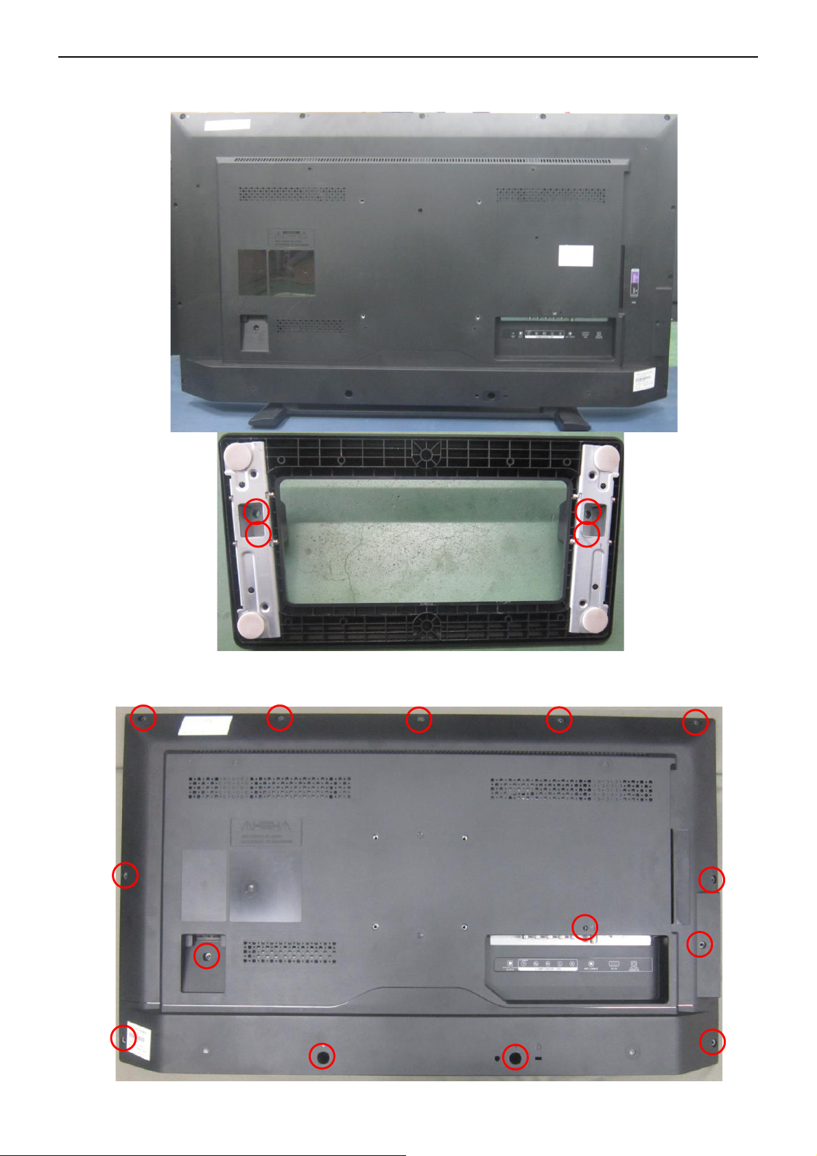
4. Mechanical Instructions
LC-32LB261U
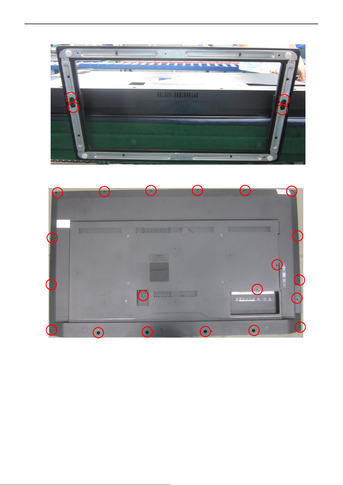
1. Remove the screw to remove the BASE.
2. Remove the screw to remove the REAR COVER.
32″&42″&50″LCD TV Best Buy LC-32LB261U- LC-42LB261U- LC-50LB261U
10
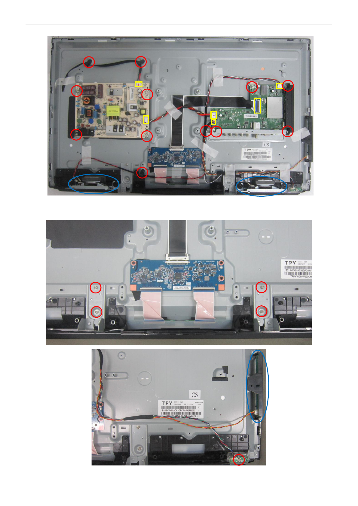
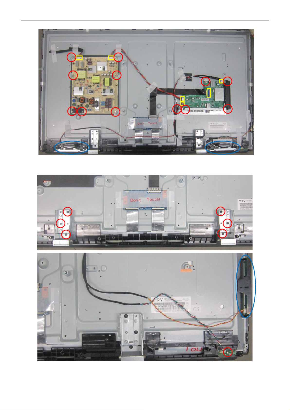
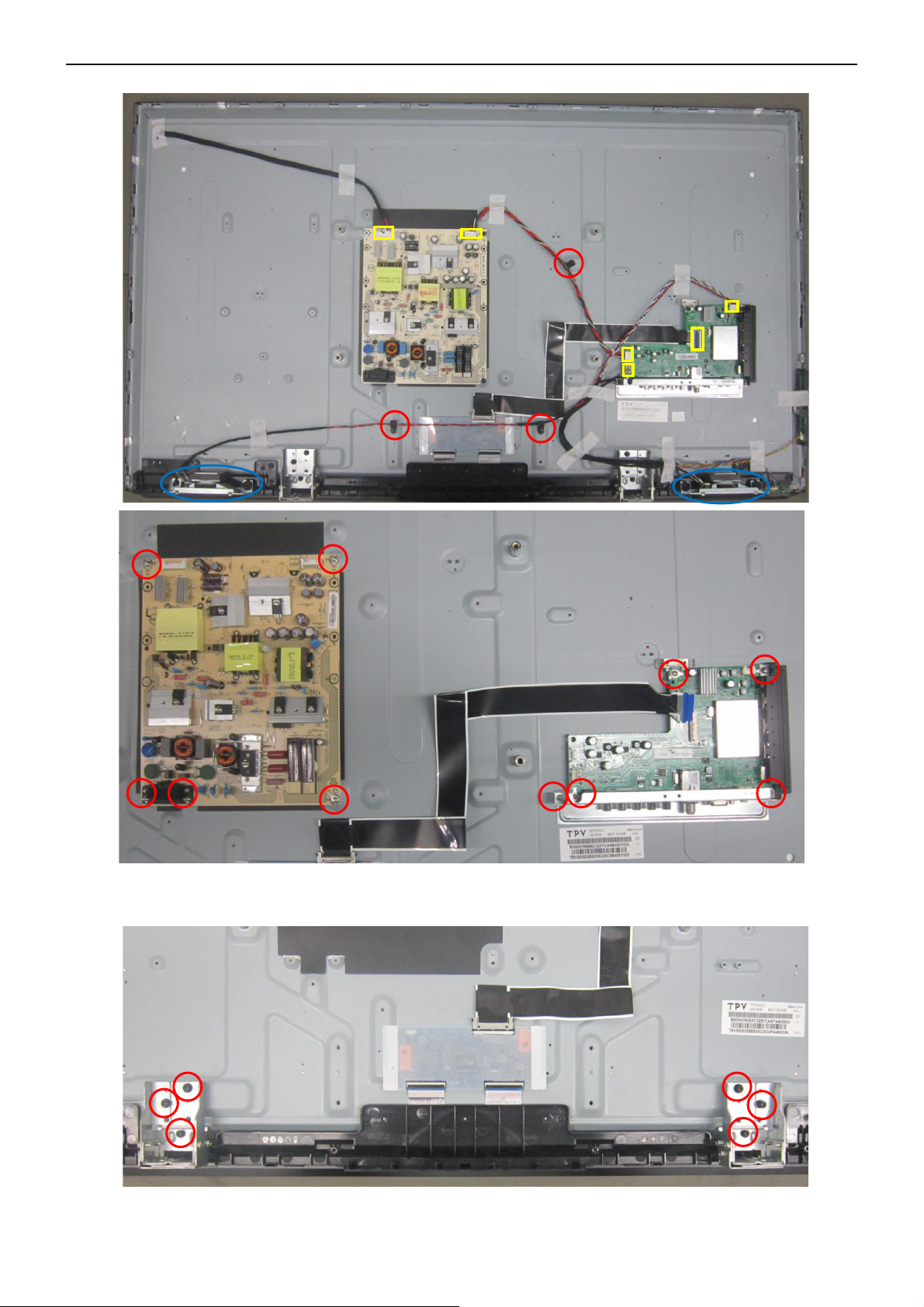
3. Remove the connectors and screws to remove MAIN BOARD, POWER BOARD, SPEAKERS, BKT_IO.
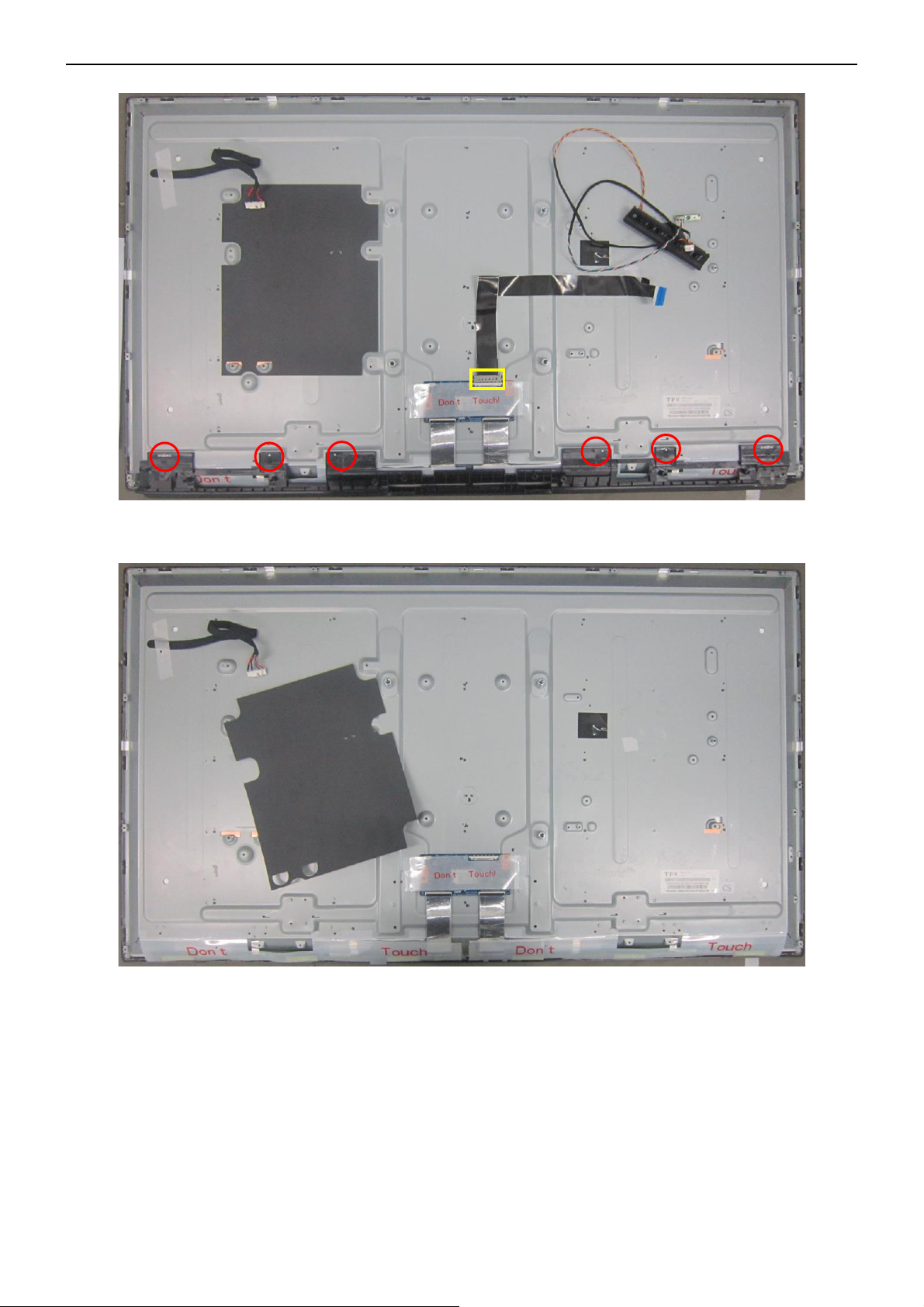
4. Remove the screw to remove BKT_STAND, KEYPAD, IR BOARD.
32″&42″&50″LCD TV Best Buy LC-32LB261U- LC-42LB261U- LC-50LB261U
11
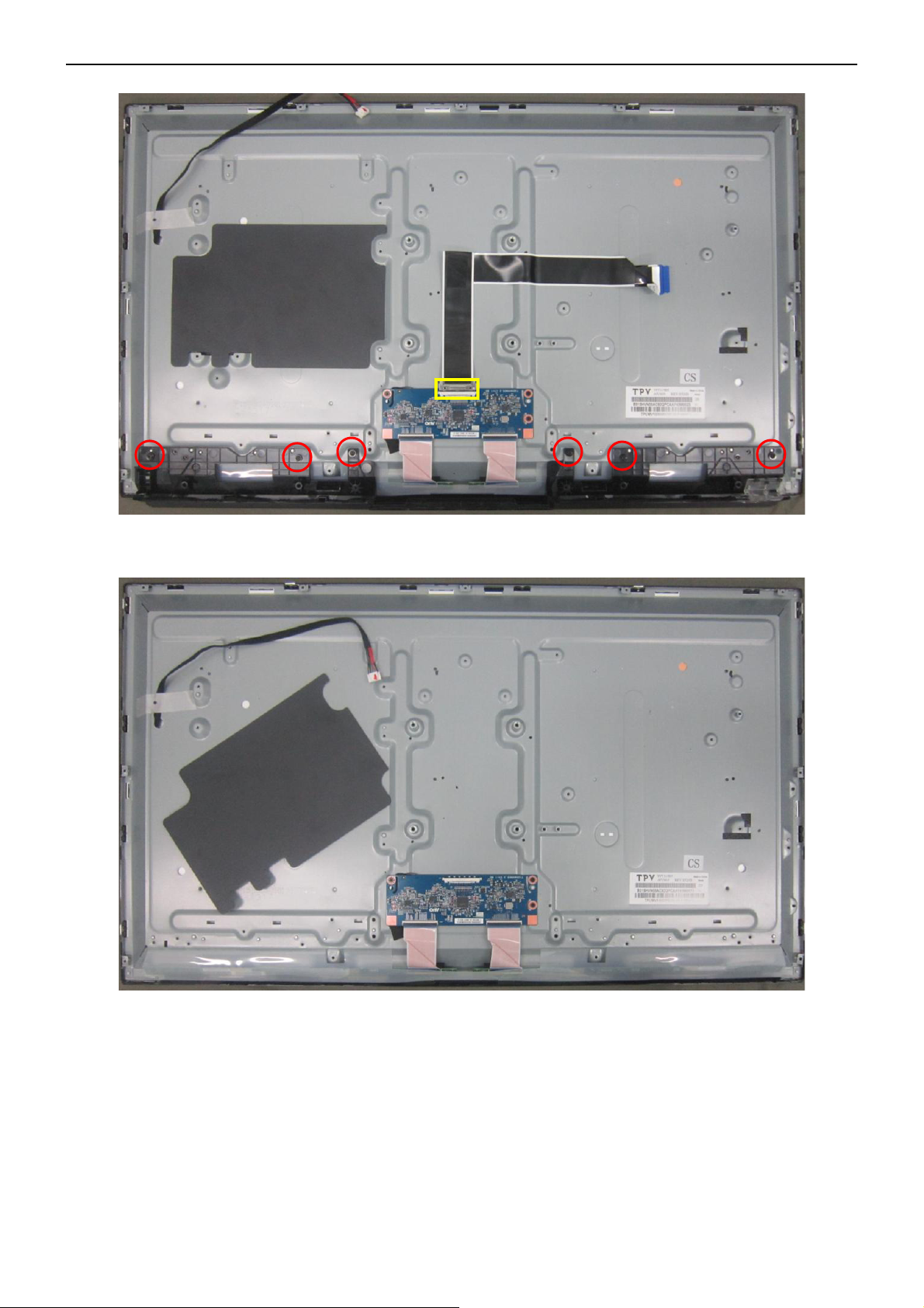
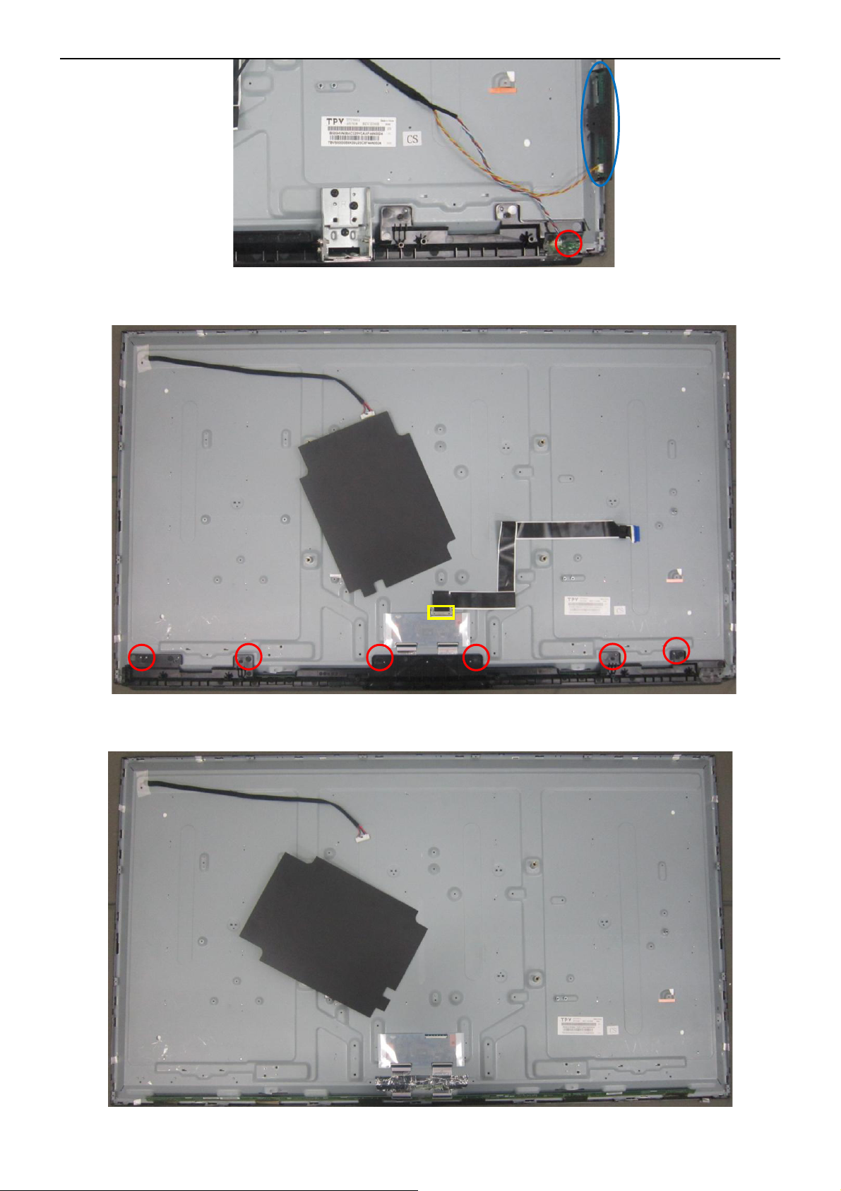
5. Remove the screw to remove FFC CABLE, DECO.
6. PANEL.
32″&42″&50″LCD TV Best Buy LC-32LB261U- LC-42LB261U- LC-50LB261U
12
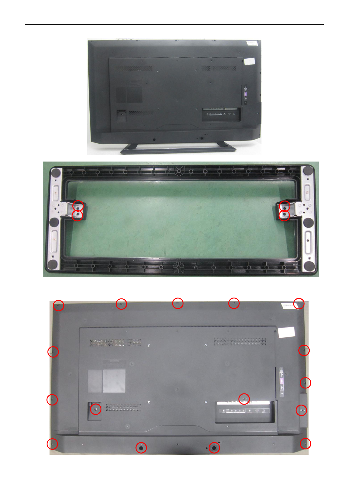
LC-42LB261U
1. Remove the screw to remove the BASE.
2. Remove the screw to remove the REAR COVER.
32″&42″&50″LCD TV Best Buy LC-32LB261U- LC-42LB261U- LC-50LB261U
13
3. Remove the connectors and screws to remove MAIN BOARD, POWER BOARD, SPEAKERS, BKT_IO.
4. Remove the screw to remove BKT_STAND, KEYPAD, IR BOARD.
32″&42″&50″LCD TV Best Buy LC-32LB261U- LC-42LB261U- LC-50LB261U
14
5. Remove the screw to remove FFC CABLE, DECO.
6. PANEL.
32″&42″&50″LCD TV Best Buy LC-32LB261U- LC-42LB261U- LC-50LB261U
15
LC-50LB261U
1. Remove the screw to remove the BASE.
2. Remove the screw to remove the REAR COVER.
32″&42″&50″LCD TV Best Buy LC-32LB261U- LC-42LB261U- LC-50LB261U
16
3. Remove the connectors and screws to remove MAIN BOARD, POWER BOARD, SPEAKERS, BKT_IO.
4. Remove the screw to remove BKT_STAND, KEYPAD, IR BOARD.
32″&42″&50″LCD TV Best Buy LC-32LB261U- LC-42LB261U- LC-50LB261U
17
5. Remove the screw to remove FFC CABLE, DECO.
6. PANEL.

32″&42″&50″LCD TV Best Buy LC-32LB261U- LC-42LB261U- LC-50LB261U
18
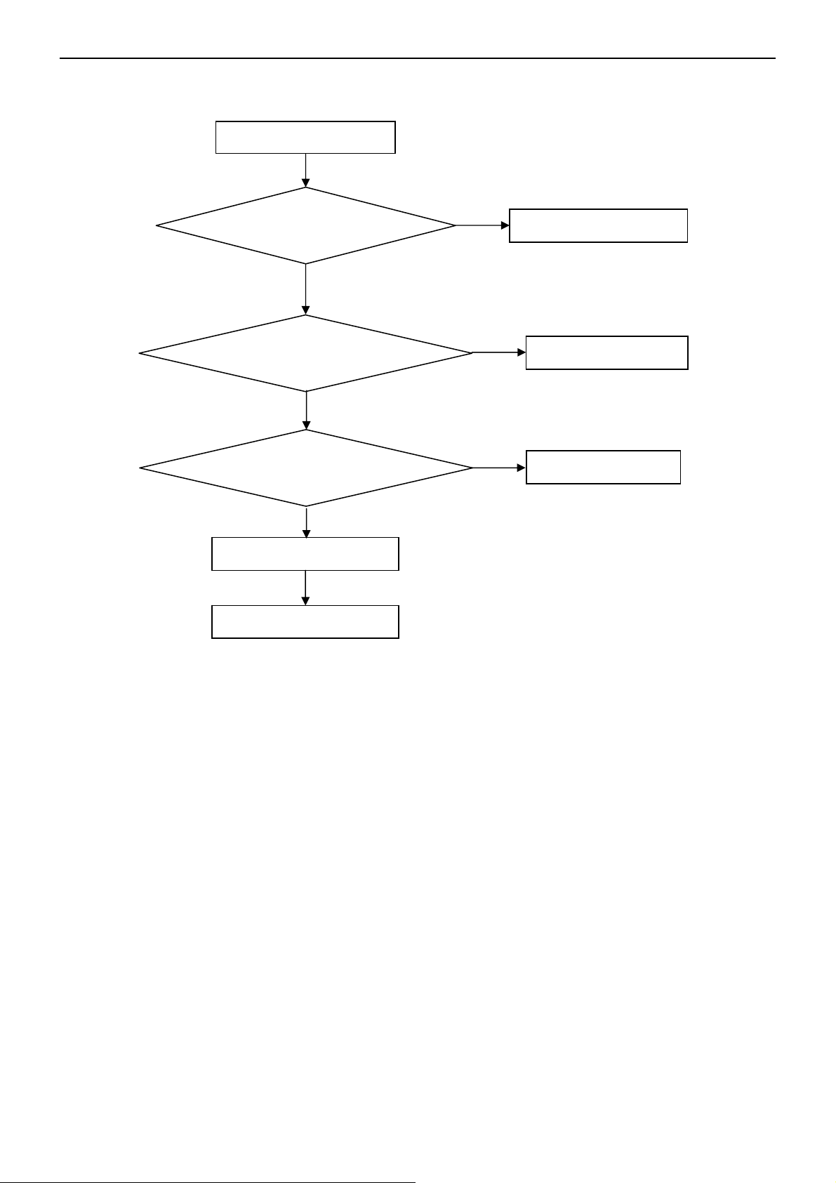
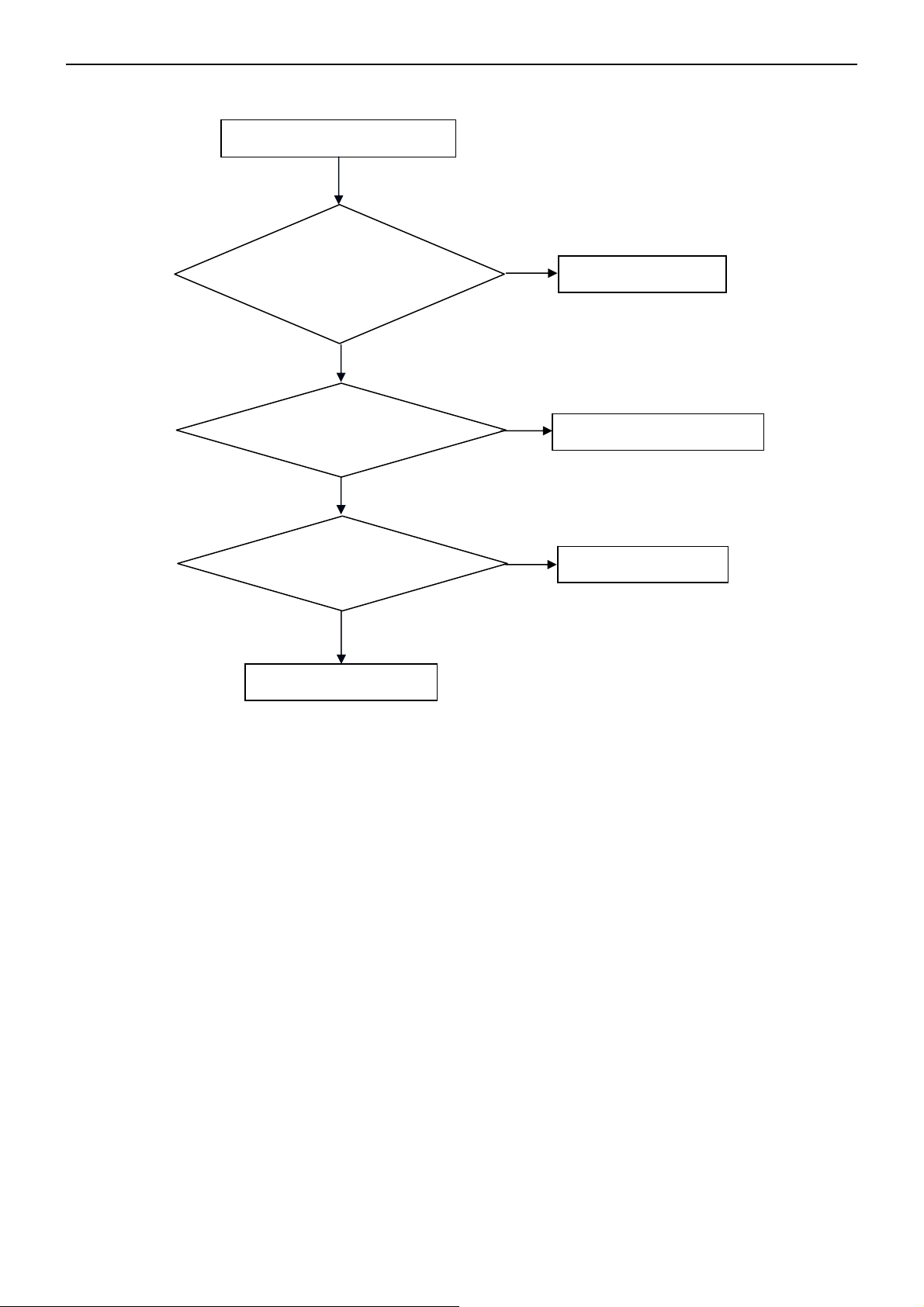
5. Repair Flow Chart
1. No power
No power (LED “Off”)
Check the AC input and
the
p
ower is “ON”?
Power “On”
Check the IR board and LED
Replace the IR board
Replace the main board
Power board
out
p
ut=12V
,
5V?
Replace the power board
No
Yes
No
Yes
No
32″&42″&50″LCD TV Best Buy LC-32LB261U- LC-42LB261U- LC-50LB261U
19
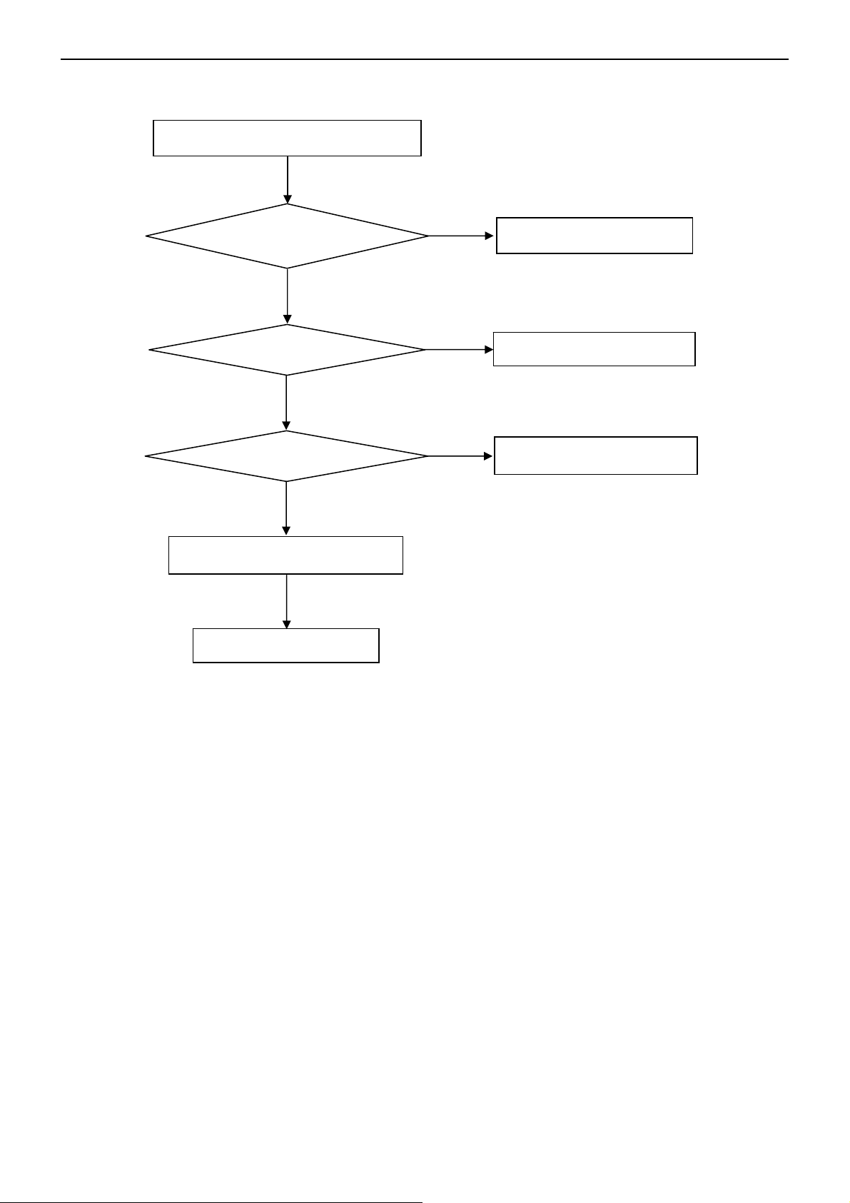
2. Can’t start
Can’t start(LED red)
Replace the main board
Replace the Power board
No
Yes
No
Yes
No
No
Power board output=12,19.5V?
Check the power key is under control?
Check the IR receiver is normal?
Replace the power board
Replace the key board
Yes
Replace the IR board

32″&42″&50″LCD TV Best Buy LC-32LB261U- LC-42LB261U- LC-50LB261U
20
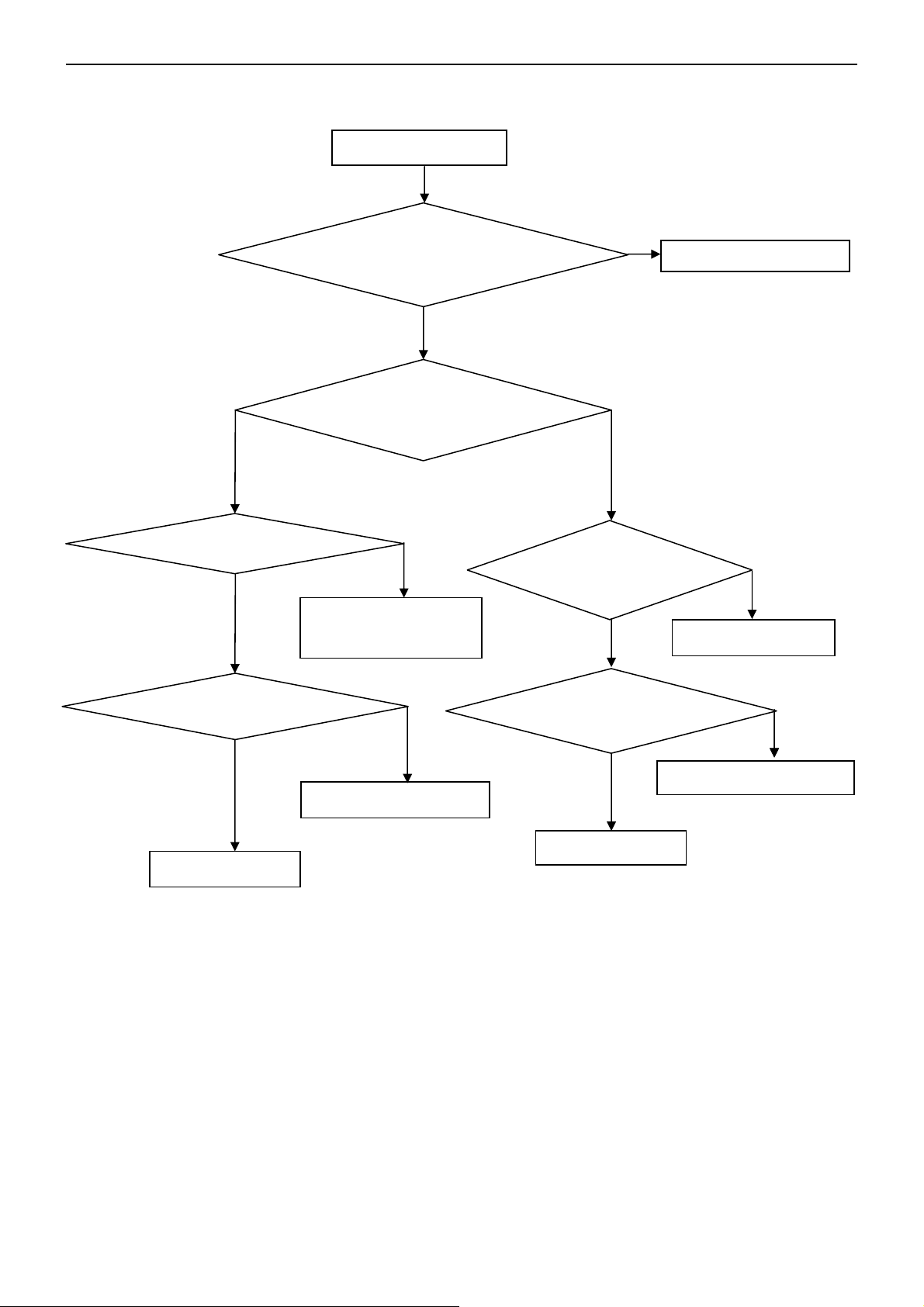
3. Abnormal display
Abnormal Display
Reset the source
Check the source
Check the panel
Replace the main board
Replace the LVDS cable
Replace the panel
No
No
No
Yes
Yes
Yes
No
No
Check the main board
Enter factory mode to do
“EEPROM initial”&“Reset”
Check the LVDS cable
32″&42″&50″LCD TV Best Buy LC-32LB261U- LC-42LB261U- LC-50LB261U
21
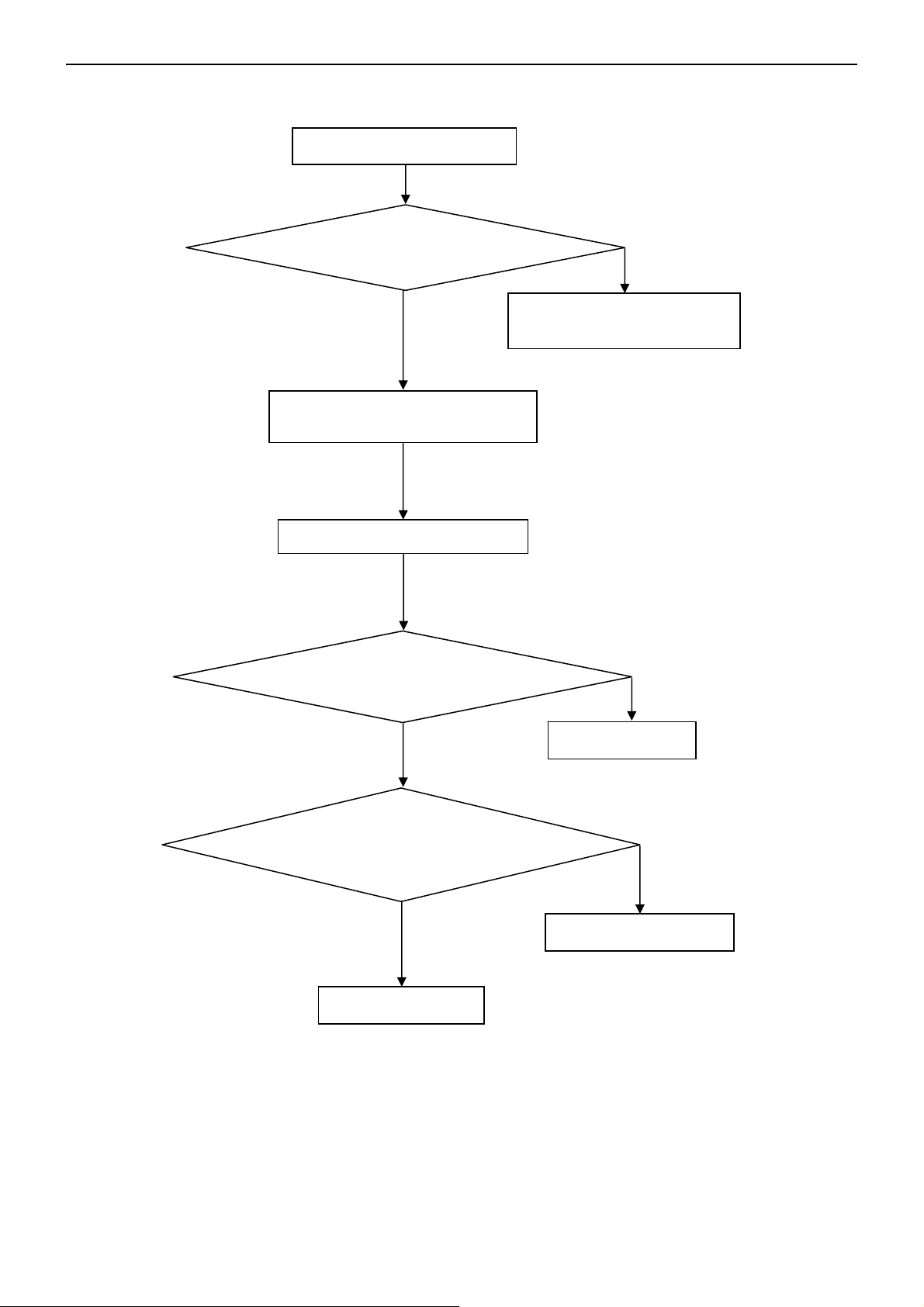
4. No display
Check the B/L
signal is available?
Replace main board
Replace the power board
Panel Vcc = 12V?
Replace the Panel
No display (LED blue)
Replace the main board
Check the backlight is
“On”?
Check the LVDS cable
Reinsert or replace the
LVDS cable
Replace the main board
Replace the Panel
No
Yes
Yes
No
Yes
No
No
Yes
Yes
No
Yes
No
Power board output=12V,19.5V?
Check TV is under control and power
on/off by remote control and power key?
32″&42″&50″LCD TV Best Buy LC-32LB261U- LC-42LB261U- LC-50LB261U
22
5. Sound problem
No
Check the cable between the
speakers and main board is OK?
No sound or sound abnormal
Check the TV is muted, adjust the
volume or enter the menu to reset?
Reinsert the audio cable or
change the TV system
Replace the cable
Replace the speaker
Replace the main board
No
Yes
Check the speaker resistance value is in spec
(Remark: The value is marked on the speaker)?
Check the audio source connection
and the TV system are correct?
Yes
No
Yes
No
Enter factory mode to do “Reset”
No
32″&42″&50″LCD TV Best Buy LC-32LB261U- LC-42LB261U- LC-50LB261U
23
6. Remote control malfunction
Remote Control malfunction
Replace the battery
Replace the remote control
Whether the IR board is
abnormal?
Yes
No
Replace the IR board
Replace the main board
No
Yes
No
Yes
Use the other remote controls
Check the remote control battery is
not properly placed or no power?
32″&42″&50″LCD TV Best Buy LC-32LB261U- LC-42LB261U- LC-50LB261U
24
7. OSD is unstable or can’t work normally
Key board connected properly?
Reconnect the key board
Buttons are OK?
Replace the button function
Yes
No
Key board is OK?
Replace the key board
Replace the main board
No
Yes
No
No
OSD is unstable or can’t work normally
Enter factory mode to do “Reset”
Yes
32″&42″&50″LCD TV Best Buy LC-32LB261U- LC-42LB261U- LC-50LB261U
25
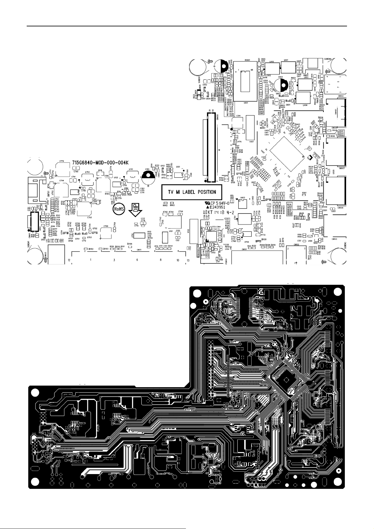
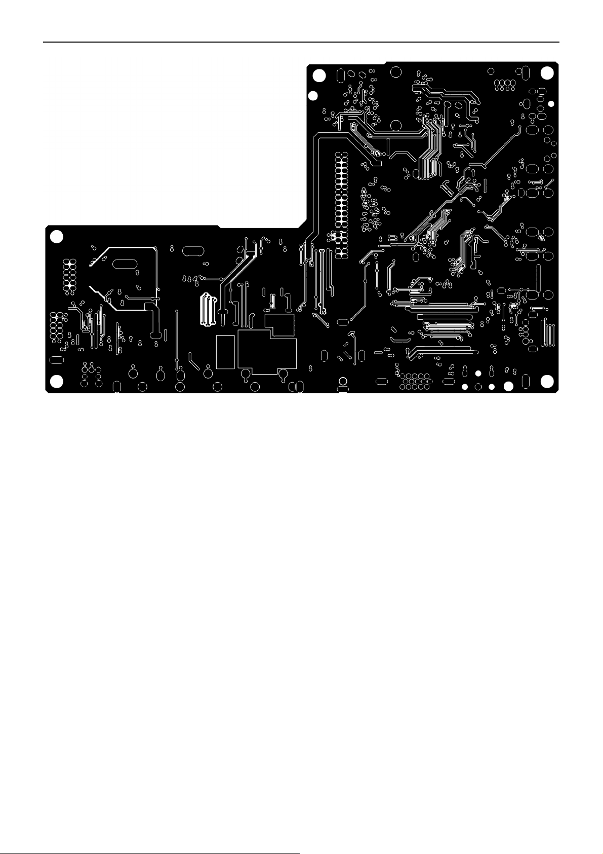
6. PCB Layout
6.1 Main Board
715G6840M0D000004
32″&42″&50″LCD TV Best Buy LC-32LB261U- LC-42LB261U- LC-50LB261U
26
32″&42″&50″LCD TV Best Buy LC-32LB261U- LC-42LB261U- LC-50LB261U
27
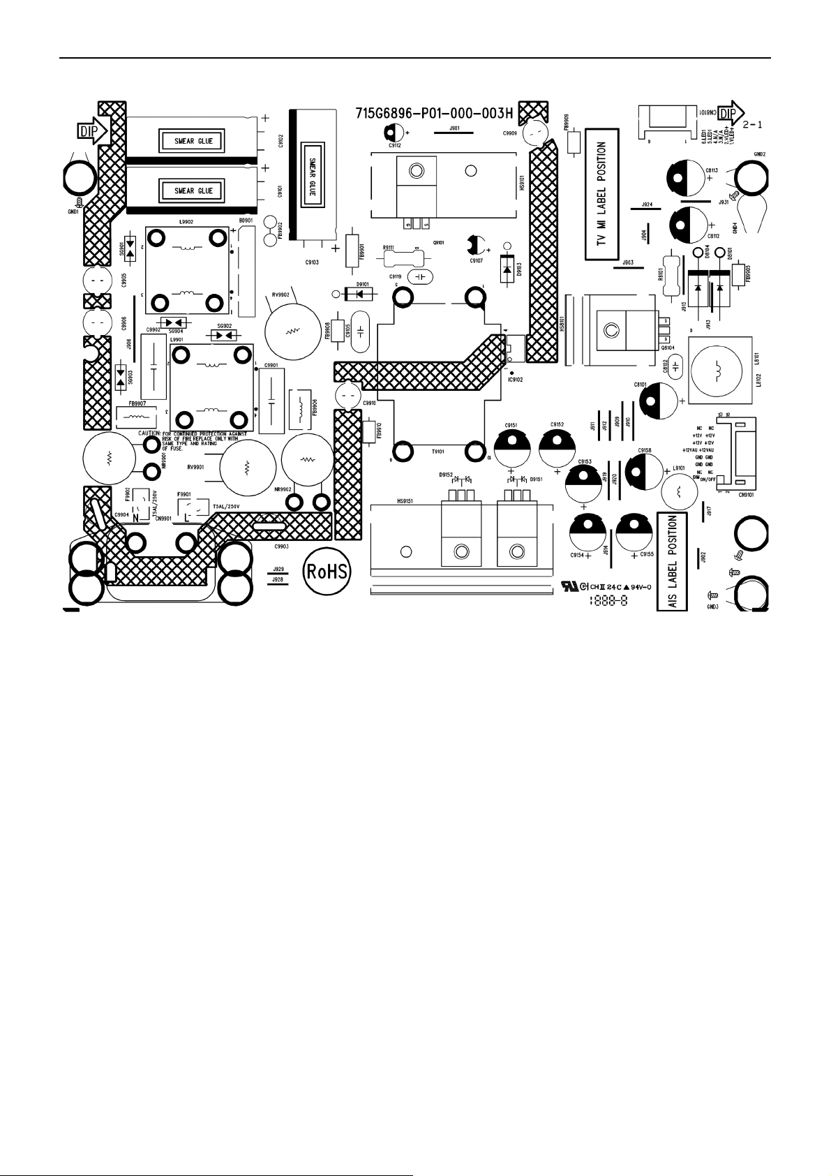
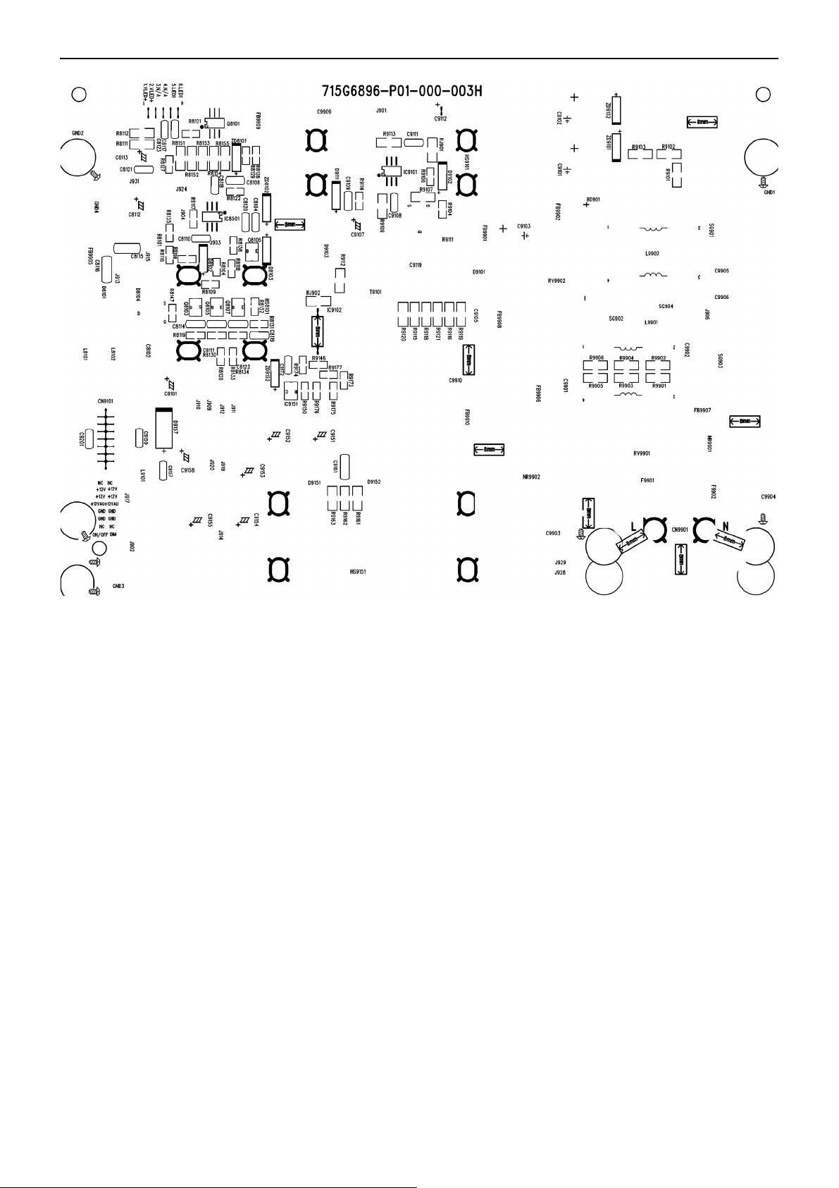
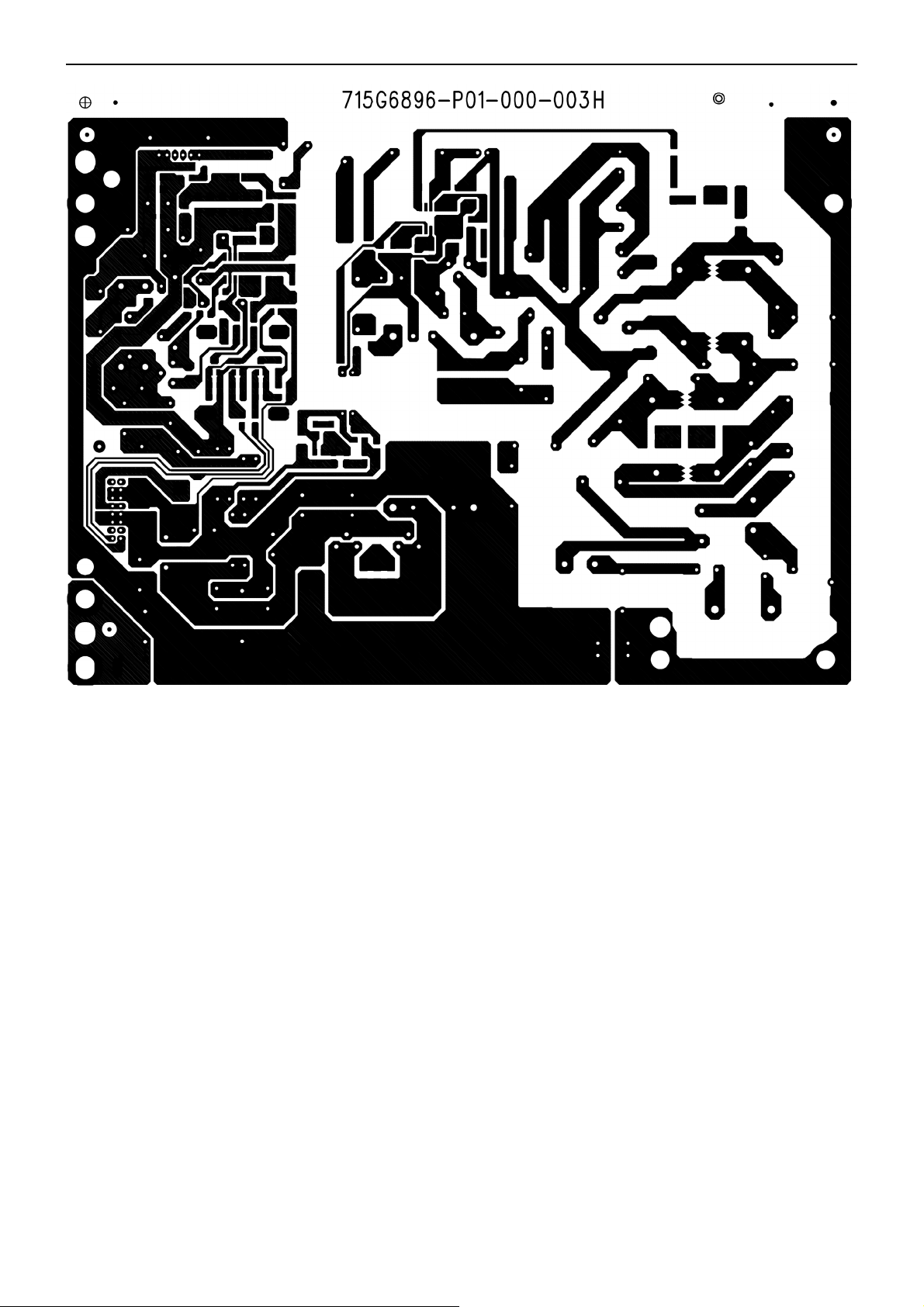
6.2 Power Board
715G6896P01000003H (32”)
32″&42″&50″LCD TV Best Buy LC-32LB261U- LC-42LB261U- LC-50LB261U
28
32″&42″&50″LCD TV Best Buy LC-32LB261U- LC-42LB261U- LC-50LB261U
29
32″&42″&50″LCD TV Best Buy LC-32LB261U- LC-42LB261U- LC-50LB261U
30
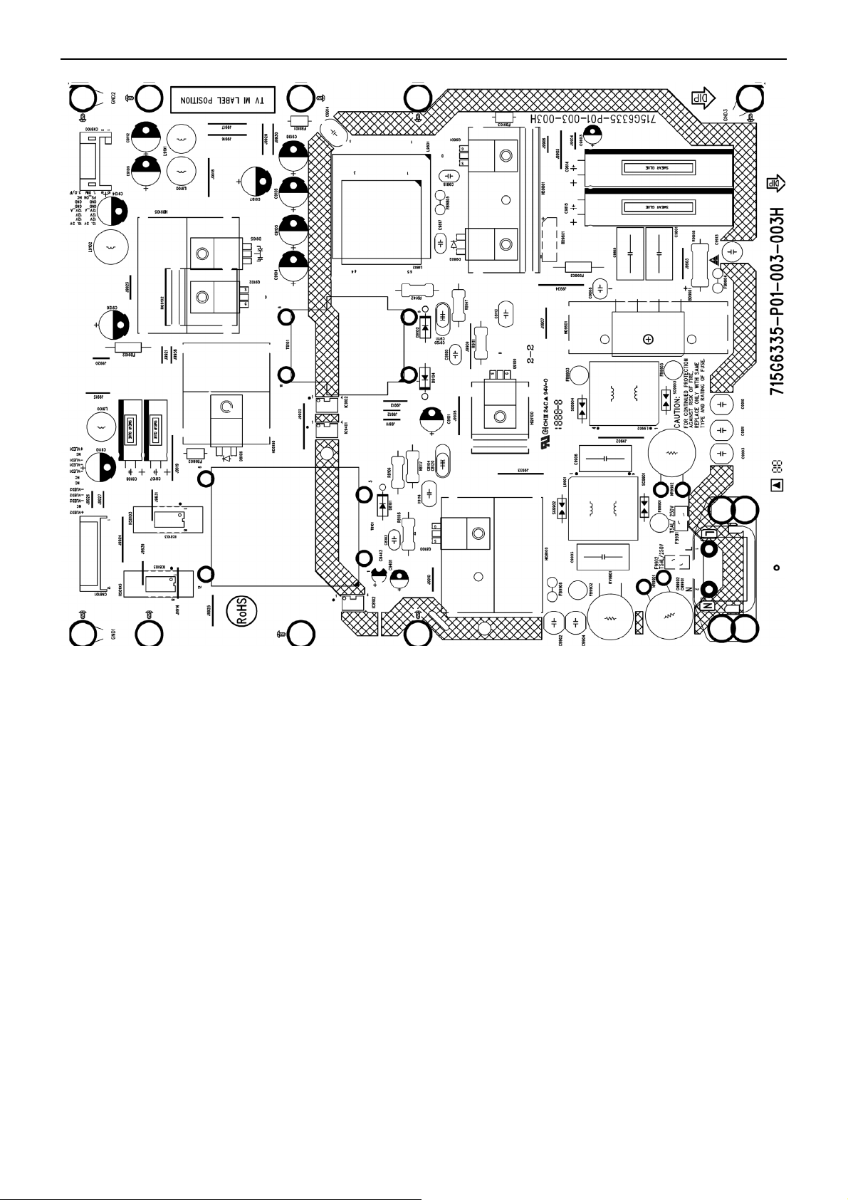
715G6335P01003003 (42” & 50”)
 Loading...