


LC-32RD2E
Table of contents
 Loading...
Sharp LC-32RD2E, LC-32RD2S, LC-37RD2E, LC-37RD2S, LC-42RD2E Operating Manual
...
LC-32RD2E
LC-32RD2S
LC-37RD2E
ENGLISH
LC-37RD2S
LC-42RD2E
LC-42RD2S
LCD COLOUR TELEVISION
LCD-FARBFERNSEHGERÄT
TÉLÉVISION COULEUR À ÉCRAN
À CRISTAUX LIQUIDES (LCD)
TELEVISORE A COLORI LCD
LCD-KLEURENTELEVISIE
TELEVISIÓN EN COLOR LCD
OPERATION MANUAL
BEDIENUNGSANLEITUNG
MODE D’EMPLOI
MANUALE DI ISTRUZIONI
GEBRUIKSAANWIJZING
DEUTSCH
FRANÇAIS
ITALIANO
NEDERLANDS
MANUAL DE MANEJO
ESPAÑOL

200.0
200,0
85.0
85,0
200.0
200,0
(795.0) / [917.0] / ((1027.0))
(795,0) / [917,0] / ((1027,0))
(80.7) / [101.8]
(80,7) / [101,8]
((97.7))
((97,7))
(255.0) / [306.4]
(255,0) / [306,4]
((306.4))
((306,4))
(123.7) / [125.3]
(123,7) / [125,3]
((141.6))
((141,6))
(700.0) / [822.6] / ((933.0))
(700,0) / [822,6] / ((933,0))
(506.0) / [543.0] / ((543.0))
(506,0) / [543,0] / ((543,0))
(588.0) / [657.0] / ((724.0))
(588,0) / [657,0] / ((724,0))
(531.0) / [600.0] / ((667.0))
(531,0) / [600,0] / ((667,0))
(343.0) / [378.0] / ((413.0))
(343,0) / [378,0] / ((413,0))
(395.0) / [463.8] / ((526.0))
(395,0) / [463,8] / ((526,0))
(57.0) / [58.0]
(57,0) / [58,0]
((57.0))
((57,0))
The mains lead of this product is fitted with a non-rewireable (moulded) plug incorporating a 13A fuse. Should
the fuse need to be replaced, a BSI or ASTA approved BS 1362 fuse marked or
as above, which is also indicated on the pin face of the plug, must be used.
Always refit the fuse cover after replacing the fuse. Never use the plug without the fuse cover fitted.
mains plug and fit an appropriate type.
In the unlikely event of the socket outlet in your home not being compatible with the plug supplied, cut off the
DANGER:
The fuse from the cut-off plug should be removed and the cut-off plug destroyed immediately and disposed of
in a safe manner.
Under no circumstances should the cut-off plug be inserted elsewhere into a 13A socket outlet, as a serious
electric shock may occur.
To fit an appropriate plug to the mains lead, follow the instructions below:
IMPORTANT:
The wires in the mains lead are coloured in accordance with the following code:
As the colours of the wires in the mains lead of this product may not correspond with the coloured markings
identifying the terminals in your plug, proceed as follows:
• The wire which is coloured blue must be connected to the plug terminal which is marked N or coloured black.
• The wire which is coloured brown must be connected to the plug terminal which is marked L or coloured red.
Ensure that neither the brown nor the blue wire is connected to the earth terminal in your three-pin plug.
Before replacing the plug cover make sure that:
• If the new fitted plug contains a fuse, its value is the same as that removed from the cut-off plug.
• The cord grip is clamped over the sheath of the mains lead, and not simply over the lead wires.
IF YOU HAVE ANY DOUBT, CONSULT A QUALIFIED ELECTRICIAN.
Blue: Neutral
Brown: Live
SPECIAL NOTE FOR USERS IN THE U.K.
ASA
and of the same rating

OPERATION MANUAL
ENGLISH
• The illustrations and on-screen displays in this operation manual are for explanation purposes and may vary slightly from
the actual operations.
• The examples used throughout this manual are based on the LC-32RD2E model.
• The factory preset PIN is “1234”.
these icons used throughout this manual indicate
TV only
TV/AV only PC onlyAV only
TV/DTV/AV only
:
the menu item can be set or adjusted only in the
selected input mode.
Contents
ENGLISH
Contents …………………………………………………………… 1
Dear SHARP customer …………………………………………… 2
Important Safety Precautions ………………………………… 2
Trademarks ………………………………………………………… 2
Supplied accessories …………………………………………… 3
Quick guide ………………………………………………………… 3
Attaching the stand …………………………………………… 3
Setting the TV ………………………………………………… 4
Inserting the batteries ………………………………………… 5
Using the remote control unit ……………………………… 5
Cautions regarding the remote control unit ………… 5
Remote control unit …………………………………………… 6
TV (Front view) ………………………………………………… 7
TV (Rear view) ………………………………………………… 7
Turning on the power ………………………………………… 8
Standby mode ………………………………………………… 8
Initial auto installation (Analogue) ………………………… 8
Using the analogue programme list ………………………… 8
Initial auto installation (DTV) ………………………………… 8
Using external equipment ……………………………………… 9
Connecting a VCR …………………………………………… 9
Connecting a game console or camcorder ……………… 9
Connecting a DVD player …………………………………… 9
Connecting a decoder ……………………………………… 10
Connecting a PC ……………………………………………… 10
Using AV Link function ……………………………………… 10
Menu operations ………………………………………………… 11
Menu operation buttons ……………………………………… 11
On-Screen Display …………………………………………… 11
Common operations ………………………………………… 12
Picture menu ………………………………………………… 13
AV Mode ………………………………………………… 13
OPC ……………………………………………………… 13
Picture adjustments …………………………………… 13
Advanced………………………………………………… 14
Colour Temp. ……………………………………… 14
Black………………………………………………… 14
3D-Y/C ……………………………………………… 14
Monochrome ……………………………………… 14
Film Mode ………………………………………… 14
100Hz (truD®) ……………………………………… 14
Audio menu ………………………………………………… 14
AV Mode ………………………………………………… 14
Audio adjustments ……………………………………… 14
Surround ………………………………………………… 15
Auto Vol. ………………………………………………… 15
Clear Voice ……………………………………………… 15
Power Control menu ………………………………………… 15
No Signal Off …………………………………………… 15
No Operation Off………………………………………… 15
Power Management …………………………………… 15
Setup menu ………………………………………………… 15
Auto Installation ………………………………………… 15
Programme Setup ……………………………………… 16
Auto Search………………………………………… 16
Manual Adjust ……………………………………… 16
Fine …………………………………………… 16
Colour sys. …………………………………… 16
Sound sys. (Broadcasting system) ………… 16
Label ………………………………………… 16
Skip …………………………………………… 16
Decoder ……………………………………… 16
Lock …………………………………………… 17
Sort ………………………………………………… 17
Erase Programme ………………………………… 17
Child Lock ……………………………………………… 17
Input Label ……………………………………………… 17
Fine Sync. ……………………………………………… 18
XGA Mode ……………………………………………… 18
Position ………………………………………………… 18
WSS (Wide Screen Signalling) ………………………… 18
4:3 Mode ………………………………………………… 18
Language ………………………………………………… 18
Supply Voltage ………………………………………… 18
Option menu ………………………………………………… 18
Audio Only ……………………………………………… 18
DNR (Digital Noise Reduction) ………………………… 19
HDMI Setup ……………………………………………… 19
Input Select ……………………………………………… 19
Colour System …………………………………………… 19
Useful features …………………………………………………… 20
WIDE MODE ………………………………………………… 20
Still image ……………………………………………………… 21
Teletext function ……………………………………………… 21
DTV menu operations …………………………………………… 22
DTV menu operation buttons ……………………………… 22
DTV On-Screen Display ……………………………………… 22
DTV common operations …………………………………… 22
About using the character set screen ………………… 23
Language ……………………………………………………… 23
Programme Setup …………………………………………… 23
Favourite …………………………………………… 24
Lock ………………………………………………… 24
Move ………………………………………………… 24
Move To …………………………………………… 24
Skip ………………………………………………… 24
Select ……………………………………………… 25
Erase ……………………………………………… 25
Label………………………………………………… 25
View ………………………………………………… 25
Installation …………………………………………………… 25
Auto Installation ………………………………………… 25
Carrier Scan……………………………………………… 25
Carrier Setup …………………………………………… 26
System Setup ………………………………………………… 26
OSD Setup ……………………………………………… 26
Child Lock ……………………………………………… 27
Accessories ………………………………………………… 27
Software Version ………………………………………… 27
Software Upgrade ……………………………………… 27
Common Interface …………………………………………… 28
Inserting a CA card …………………………………… 28
Supplying power to the antenna …………………………… 28
Useful features (DTV) …………………………………………… 29
About EPG ………………………………………………… 29
Using the EPG …………………………………………… 29
Using the EPG Timer …………………………………… 29
Using the ESG ………………………………………………… 30
Using the digital programme list …………………………… 30
Viewing a service banner …………………………………… 30
Using the multi audio function ……………………………… 31
Displaying subtitles …………………………………………… 31
Using the MHEG5 application (UK only) …………………… 31
Appendix …………………………………………………………… 32
Troubleshooting ……………………………………………… 32
PC compatibility chart ……………………………………… 33
RS-232C port specifications ………………………………… 33
Specifications ………………………………………………… 35
Optional accessories ………………………………………… 35
End of life disposal …………………………………………… 36
1

Dear SHARP customer
Thank you for your purchase of the SHARP LCD colour TV product. To ensure safety and many years of troublefree operation of your product, please read the Important Safety Precautions carefully before using this product.
Important Safety Precautions
• Cleaning—Unplug the AC cord from the AC outlet before cleaning the product. Use a damp cloth to clean the
product. Do not use liquid cleaners or aerosol cleaners.
• Water and moisture—Do not use the product near water, such as bathtub, washbasin, kitchen sink, laundry tub,
swimming pool and in a wet basement.
• Do not place vases or any other water-filled containers on this product.
The water may spill onto the product causing fire or electric shock.
• Stand—Do not place the product on an unstable cart, stand, tripod or table. Doing so can
cause the product to fall, resulting in serious personal injuries as well as damage to the product.
Use only a cart, stand, tripod, bracket or table recommended by the manufacturer or sold with
the product. When mounting the product on a wall, be sure to follow the manufacturer’s
instructions. Use only the mounting hardware recommended by the manufacturer.
• When relocating the product placed on a cart, it must be moved with utmost care. Sudden stops,
excessive force and uneven floor surface can cause the product to fall from the cart.
• Ventilation—The vents and other openings in the cabinet are designed for ventilation. Do not
cover or block these vents and openings since insufficient ventilation can cause overheating
and/or shorten the life of the product. Do not place the product on a bed, sofa, rug or other similar surface, since
they can block ventilation openings. This product is not designed for built-in installation; do not place the product
in an enclosed place such as a bookcase or rack, unless proper ventilation is provided or the manufacturer’s
instructions are followed.
• The LCD panel used in this product is made of glass. Therefore, it can break when the product is dropped or
impact applied. If the LCD panel is broken, be careful not to be injured by broken glass.
• Heat sources—Keep the product away from heat sources such as radiators, heaters, stoves and other heatgenerating products (including amplifiers).
• To prevent fire, never place any type of candle or naked flames on the top or near the TV set.
• To prevent fire or shock hazard, do not place the AC cord under the TV set or other heavy items.
• Do not display a still picture for a long time, as this could cause an afterimage to remain.
• There is power consumption always if main plug is connected.
The LCD panel is a very high technology product, giving you fine picture details.
Due to the very large number of pixels, occasionally a few non-active pixels may appear on the screen as
a fixed point of blue, green or red.
This is within product specifications and does not constitute a fault.
Precautions when transporting the TV
When moving the TV, it should always be carried by two people, using both hands, be careful not to apply
pressure to the display.
Trademarks
• “HDMI, the HDMI logo and High-Definition Multimedia Interface are trademarks or registered trademarks of HDMI
Licensing LLC.”
• truD HD is a registered trademark of Micronas in Germany and other countries.
• The “HD ready” Logo is a trademark of EICTA.
• Manufactured under license from BBE Sound, Inc.
Licensed by BBE Sound, Inc. under USP5510752 and 5736897. BBE and BBE symbol are registered trademarks
of BBE Sound, Inc.
• BBE High Definition Sound restores clarity and presence for better speech intelligibility and musical realism.
2
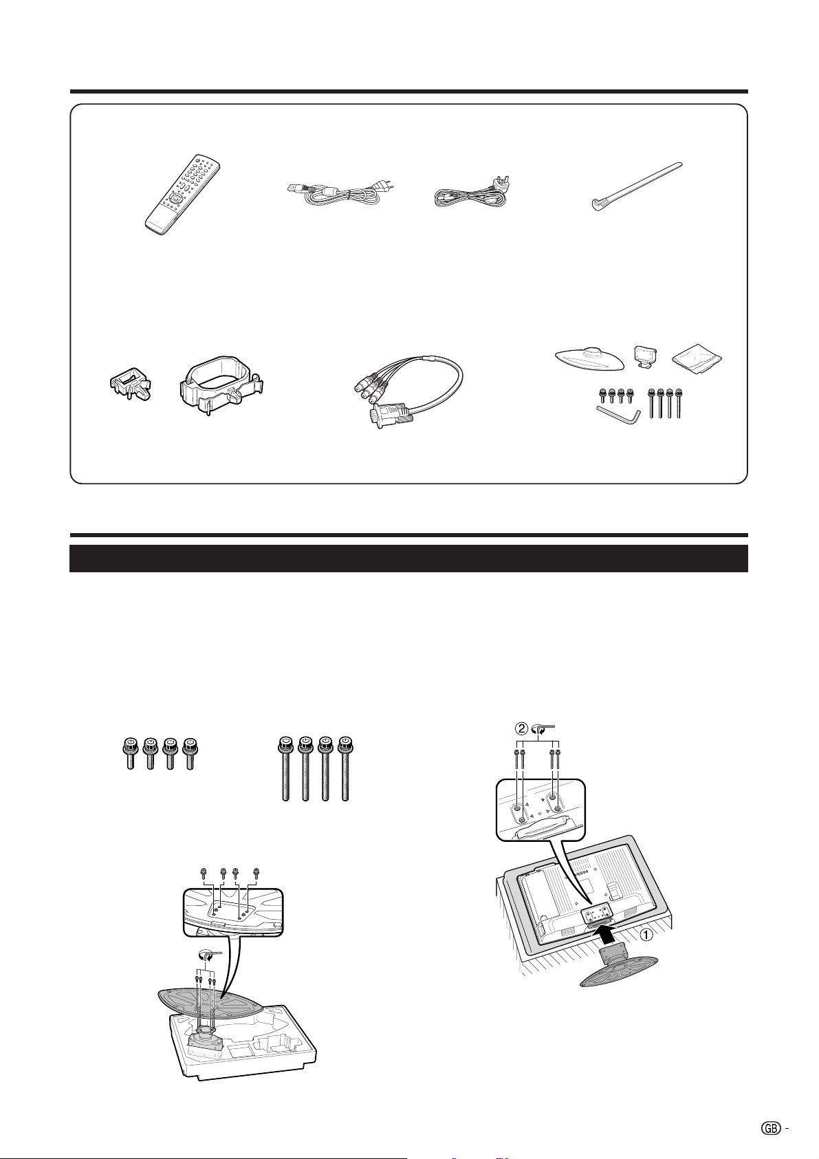
Supplied accessories
Remote control unit (g1) AC cord (g1)
(For Europe, except
U.K. and Eire)
U.K. type 3-pin AC cord is only
included with models LC-32RD2E,
LC-37RD2E,LC-42RD2E.
Pages 5 and 6
Cable clamp
(Smallg1, Largeg1)
Page 4
• “AAA” size battery (g2) ...... Page 5
3 RCA to 15-pin D-sub
adapter (g1)
Quick guide
(For U.K. and Eire)
Page 4
Page 9
• Operation manual (This publication)
Cable tie (g1)
Page 4
Stand unit (g1)
Page 3
Attaching the stand
Before performing work spread cushioning over the base area to lay the TV on, making sure the area is
completely flat. This will prevent it from being damaged.
Before attaching (or detaching) stand, unplug the AC cord from the AC INPUT terminal.
1 Confirm the 8 screws supplied with the TV.
Short screws (m4)
(used in step 2)
Long screws (m4)
(used in step 3)
3 1Insert the stand into the opening on the bottom
of the TV.
2 Insert and tighten the 4 long screws on the
rear of the TV as shown.
2 Attach the two parts of the stand unit to each other
using the 4 short screws as shown.
NOTE
• To detach the stand, perform the above steps in reverse
order.
3
Quick guide
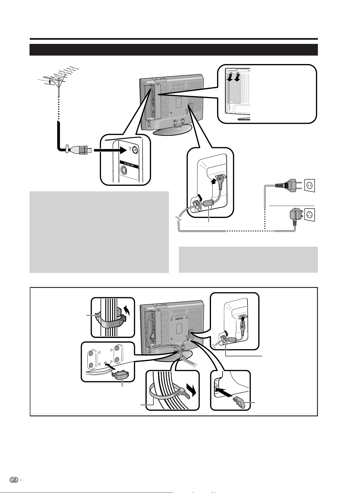
Setting the TV
Standard DIN45325 plug
(IEC 169-2)
75-ohm coaxial cable
Antenna
Connect the antenna cable from your antenna-/cable
socket or the (room-/roof) antenna for antenna input
terminal on the back of your TV set to receive digitally/
terrestrially broadcast stations.
An indoor antenna can also be used under good
reception conditions. Passive and active room
antennas are offered commercially. In an active
antenna its power is supplied via the antenna input
terminal.
The supply voltage (5V) must be correspondingly set
under “Supply Voltage”. (See page 18.)
Before making any
connections, press
down on the upper
hooks and remove the
rear terminal cover
towards you.
Place the TV close
to the AC outlet, and
keep the power plug
within reach.
(For Europe, except
U.K. and Eire)
Ferrite Core
(For U.K. and Eire)AC cord
Ferrite Core
The Ferrite Core should be permanently attached and
never removed from the AC cord.
Bundling the cables
Bundle the cables
with the clamp
(large).
Bundle the AC cord
with the clamp
(small).
Cable clamp (large)
Cable tie
Cable clamp (small)
Setting the TV on the wall
• This TV should be mounted on the wall only with the wall mount bracket available from SHARP. (See page 35.) The
use of other wall mount brackets may result in an unstable installation and may cause serious injuries.
• When you use the AN-37AG2 (SHARP) wall mount bracket, set the angle of the TV to 0° or 5°. Do not set the angle
to more than 10°.
• Installing the LCD Colour TV requires special skill that should only be performed by qualified service personnel.
Customers should not attempt to do the work themselves. SHARP bears no responsibility for improper mounting
or mounting that results in accident or injury.
• You can ask a qualified service personnel about using an optional bracket to mount the TV to the wall.
4
Quick guide
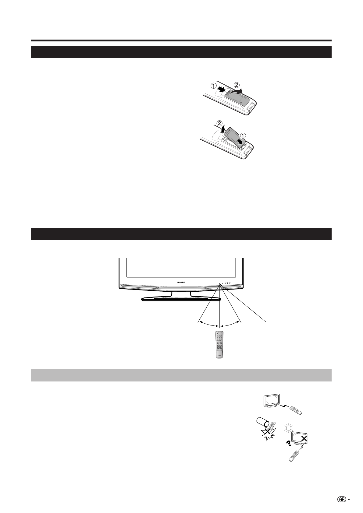
Inserting the batteries
Before using the TV for the first time, insert two “AAA” size batteries (supplied). When the batteries become
depleted and the remote control unit fails to operate, replace the batteries with new “AAA” size batteries.
1 Hold in the tab on the battery cover (1) and pull
the cover towards the direction of the arrow (2).
2 Insert two supplied “AAA” size batteries.
• Place batteries with their terminals corresponding
to the (e) and (f) indications in the battery
compartment.
3 Insert the smaller tab of the battery cover into the
opening (1), and press down on the cover until
it clicks in place (2).
CAUTION
Improper use of batteries can result in chemical leakage or explosion. Be sure to follow the instructions below.
• Do not mix batteries of different types. Different types of batteries have different characteristics.
• Do not mix old and new batteries. Mixing old and new batteries can shorten the life of new batteries or cause chemical
leakage in old batteries.
• Remove batteries as soon as they have worn out. Chemicals that leak from batteries can cause a rash. If you find any
chemical leakage, wipe thoroughly with a cloth.
• The batteries supplied with this product may have a shorter life expectancy due to storage conditions.
• If you will not be using the remote control unit for an extended period of time, remove the batteries from it.
Using the remote control unit
Use the remote control unit by pointing it towards the remote control sensor. Objects between the remote
control unit and sensor may prevent proper operation.
5 m
30°30°
Cautions regarding the remote control unit
• Do not expose the remote control unit to shock.
In addition, do not expose the remote control unit to liquids, and do not
place in an area with high humidity.
• Do not install or place the remote control unit under direct sunlight. The
heat may cause deformation of the unit.
• The remote control unit may not work properly if the remote control sensor
of the TV is under direct sunlight or strong lighting. In such case, change
the angle of the lighting or TV, or operate the remote control unit closer to
the remote control sensor.
Remote control sensor
5
Quick guide
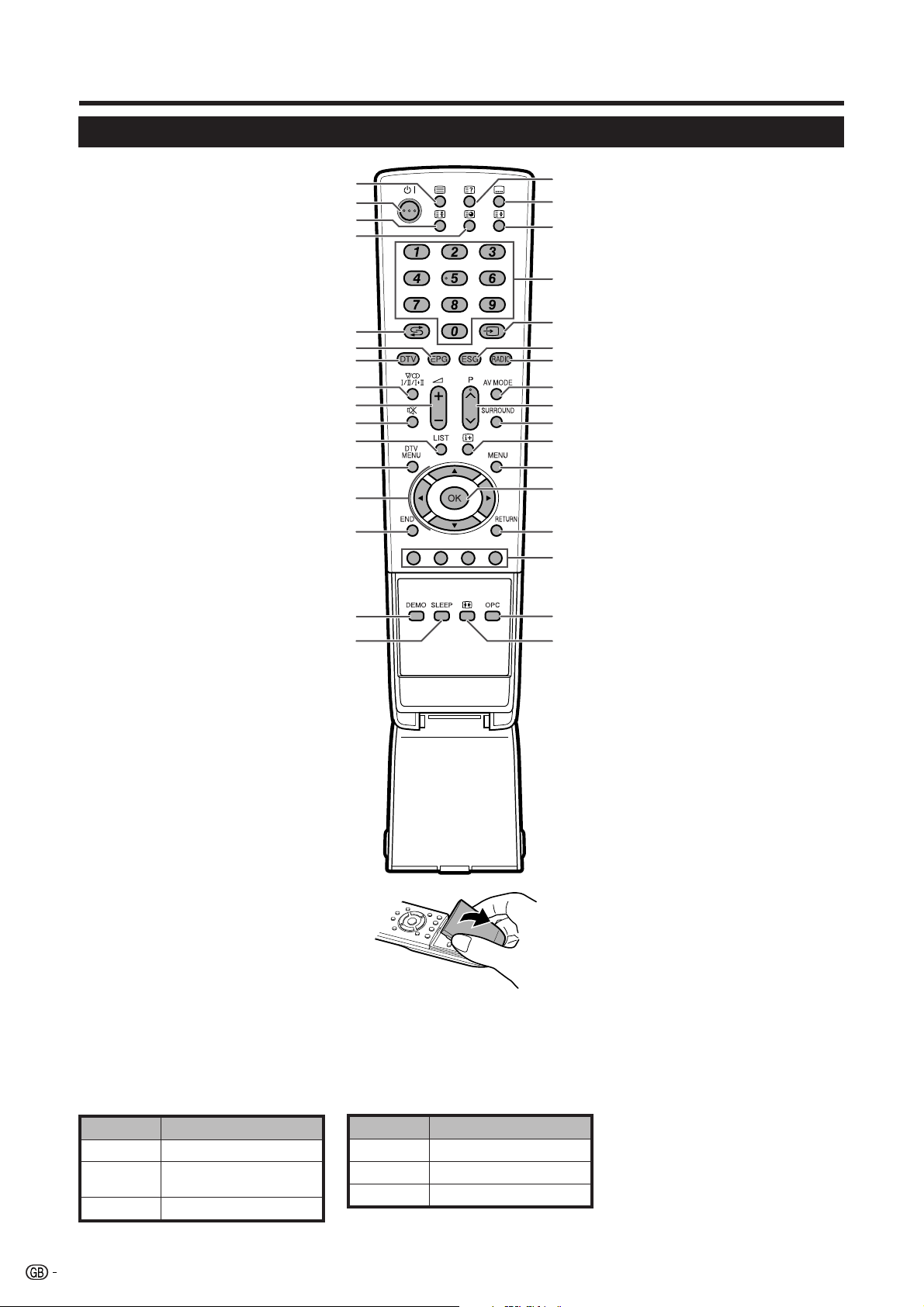
Remote control unit
1 m (Teletext)
Select the TELETEXT mode. (All TV
image, DTV/DATA image, all TEXT
image, TV/TEXT image) (See pages 21
and 31.)
DTV: Select DTV data broadcasting and
TELETEXT.
2 B (Standby/On)
Enter standby mode or turn on the
power. (See page 8.)
3 3 (Freeze/Hold)
(See page 21.)
4 1 (Subpage)
(See page 21.)
5 A (Flashback)
Press to return to the previous image
in normal viewing mode. (Will not work
while operating in EPG/ESG screen.)
6 EPG
DTV: To display EPG (Electronic
Programme Guide) screen.
7 DTV
Press to access DTV mode while
watching other input sources, and vice
versa.
(This button will not work if you were
watching DTV immediately before
turning off the TV. In this case first select
any other input source except DTV
using the b button.)
8 2 (Sound mode)
Select the sound multiplex mode.
(See below.)
9 i (k/l) (Volume)
i (k) Increase the volume.
i (l) Decrease the volume.
10 e (Mute)
Switch the sound on and off.
11 LIST
DTV: Display the programme list.
12 DTV MENU
DTV: Display DTV Menu screen.
13 a/b/c/d (Cursor)
Select a desired item on the setting
screen.
14 END
Exit the menu screen.
15 DEMO
Demonstrate the 100Hz (truD®) effects
in a dual screen format. (See page 14.)
16 SLEEP
Set the sleep timer on (in units of 30
min. up to max. 2 hr. 30 min) and off.
10
11
12
13
14
15
16
1
2
3
17
18
19
4
20
5
6
7
8
9
21
22
23
24
25
26
27
28
29
30
31
32
33
17 k (Reveal hidden Teletext)
(See page 21.)
18 [ (Subtitle for Teletext)
TV/External: To turn the subtitles on and
off. (See page 21.)
DTV: Display the subtitle selection
screen. (See page 31.)
19 v (Top/Bottom/Full)
Set the area of magnification in Teletext
mode. (See page 21.)
20 0–9
Set the channel in TV and DTV mode.
Set the page in Teletext mode.
21 b (INPUT SOURCE)
Select an input source.
(TV, DTV, EXT1, EXT2, EXT3, EXT4,
EXT5, EXT6) (See page 9.)
22 ESG
DTV: To display ESG (Electronic Service
Guide) screen. (See page 30.)
23 RADIO
DTV: Switch between RADIO and DTV
mode.
24 AV MODE
Select a video setting. (See page 13.)
25 P (r/s)
TV/DTV: Select the channel.
External: Switch to TV or DTV input
mode.
Teletext: Move to the next/previous
page.
26 SURROUND
Switch the surround effects on and off.
(See page 15.)
27 p (Display information)
(See pages 21, 29 and 30.)
28 MENU
Display the MENU screen.
(See page 11.)
29 OK
Execute a command within the menu
screen.
Display the programme list. (Except
external input.)
30 RETURN
Return to the previous menu screen.
31 Colour (Red/Green/Yellow/Blue)
TELETEXT: Select a page. (See page
21.)
DTV: The coloured buttons are used to
select correspondingly to the coloured
items in the menu screen.
32 OPC
To switch the Optical Picture Control on
and off. (See page 13.)
33 f (WIDE MODE)
Select the wide mode. (See page 20.)
E
Using 2 on the remote control unit
DTV mode:
Press 2 to open the multi audio screen. (See page 31.)
Analogue TV mode:
Each time you press 2, the mode switches as illustrated in the following tables.
NICAM TV broadcasts selection A2 TV broadcasts selection
Signal
Stereo
Bilingual
Monaural
Selectable items
NICAM STEREO, MONO
NICAM CH A, NICAM CH B,
NICAM CH AB, MONO
NICAM MONO, MONO
Signal
Stereo
Bilingual
Monaural
Selectable items
STEREO, MONO
CH A, CH B, CH AB
MONO
NOTE
• When no signal is input, the sound mode will display “MONO”.
6
Quick guide
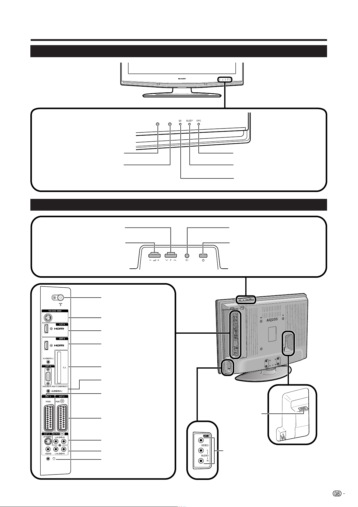
TV (Front view)
Remote control sensor
OPC sensor
TV (Rear view)
(Programme [channel] buttons)
i (l/k) (Volume buttons)
P (s/r)
Antenna input terminal
(DVB-T 5V=/80 mA)
RS-232C terminal
OPC indicator
SLEEP indicator
B (Standby/On) indicator
b (Input button)
a (Power button)
EXT 6 (HDMI) terminal
EXT 5 (HDMI/AUDIO)
terminals
COMMON INTERFACE slot
EXT 4 terminals
EXT 1 (RGB) terminal
EXT 2 (RGB) terminal
OUTPUT (Audio) terminals
EXT 3 (Rear) terminals
Headphone jack
AC INPUT terminal
EXT 3 (Side) terminals
NOTE
• Only if you use an active terrestrial antenna, select “On (5V)” under “Supply Voltage”. (See page 18.)
7
Quick guide
Turning on the power
Press a on the TV or B on the remote control unit.
Standby mode
Press B on the remote control unit when the TV is
on.
• The TV enters standby mode and the image on the screen
disappears.
• The B indicator on the TV changes from green to red.
• To completely turn off the power to the TV, unplug the AC
cord from the AC outlet. However, do not unplug the AC
cord unless otherwise instructed.
Display status indicator
Off
Red
Green
NOTE
• If you are not going to use this TV for a long period of
time, be sure to remove the AC cord from the power outlet.
• Weak electric power is still consumed even when a is
turned off.
• In DTV input mode, if the power is turned off immediately
after a setting change from the menu screen, the new
setting or channel information may not be memorised.
Power off.
The TV is in standby mode.
The TV is on.
Initial auto installation (Analogue)
When the TV powers on for the first time after purchase,
the initial auto installation (Analogue) is invoked. You
can automatically set language, country and channels
in successive operations.
NOTE
• The initial auto installation functions only once. If the initial
auto installation is not completed, (ex: When menu screen
disappeared by not operating for a few minutes, when
the power shut down, etc.), try Auto Installation from the
Setup menu. (See page 15.)
• The initial auto installation stops by pressing RETURN.
1 Setting the on-screen display language
1 Press a/b/c/d to select the desired language
listed on the screen.
2 Press OK to enter the setting.
2 Setting the country or area
1 Press a/b/c/d to select your country or area
listed on the screen.
2 Press OK to enter the setting.
• The programme auto search starts at the same time.
8
After this setting, auto search starts with the following
order:
1 Programme auto search
2 Auto labelling
3 Auto sorting
4 Preset download
You do not need to do anything during the auto search.
The setup menu disappears and you can watch the
programme on channel 1.
Using the analogue programme list
You can also select the desired channel from
programme list instead of using 0-9 numeric buttons
or P (r/s).
1 Press OK when no other menu screen is
displayed. (Except external input.)
2 Press a/b to select the desired channel to tune
in, and then press OK.
3 Press END to exit the Programme List.
Initial auto installation (DTV)
Digital Video Broadcasting is a transmission scheme.
It is much more than a simple replacement for existing
analogue television transmission. DVB provides more
stations, clearer picture quality and other services
displayed on the screen. It also allows a range of new
features and services including subtitles and multiple
audio tracks.
To watch DTV broadcasts, follow the procedures below
to scan all available services in your area.
1 Press DTV or b to access the DTV mode.
2
Press DTV MENU and the DTV Menu screen displays.
3 Press c/d to select “Installation”.
4 Press a/b to select “Auto Installation”, and then
press OK.
If you have already set the PIN, enter it here. If
not, enter the factory preset PIN “1234”.
• See page 17 for setting PIN.
• A confirmation message displays. Press c/d to
select “Yes”, and then press OK to start the search.
5 The TV starts scanning all available DTV and radio
services in your area.
NOTE
• The language and country settings used in this operation
are the settings you have already set while executing the
Initial auto installation (Analogue). If you want to
reconfigure the country setting, for instance after moving
to another country, conduct “Auto Installation” from the
Analogue Menu again.
• The services are stored according to the channel number
information embedded in the stream (if available). If the
information is not available, the services are stored
according to the order in which they were received.
If you would like to sort the order, it is possible to arrange
it as explained in page 24.
• To cancel the scan in progress, press END.
• You cannot select any DTV-related menu items unless
“Auto Installation” has been completed.
Using external equipment
Setting the input source
To view external source images, select the input source using b on the remote control unit or the TV.
NOTE
• The cables marked with * are commercially available items.
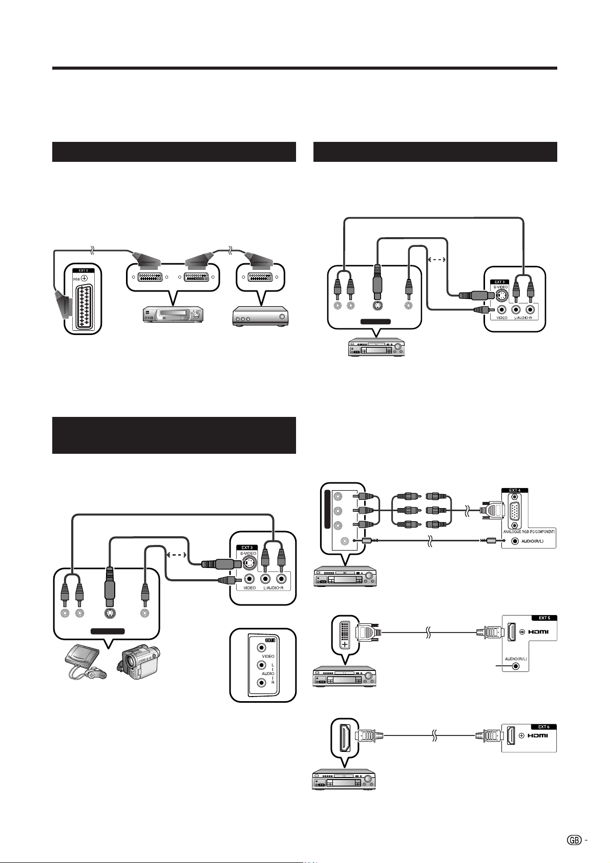
Connecting a VCR
You can use the EXT 1 or 2 terminals when connecting
a VCR and other audiovisual equipment.
If your VCR supports TV-VCR advanced AV Link
systems, you can connect the VCR to the EXT 2
terminal of the TV using the fully-wired SCART cable.
SCART cable* SCART cable*
VCR
Decoder
EXT 1 or 2
NOTE
• TV-VCR advanced AV Link systems may not be compatible
with some external sources.
• TV-OUT from EXT 1 is not outputted when EXT 5 (HDMI),
EXT 6 (HDMI) or DTV is selected as the input.
Connecting a game console or camcorder
Connecting a DVD player
You can use the EXT 2, 3, 4, 5 (HDMI) or 6 (HDMI)
terminals when connecting to a DVD player and other
audiovisual equipment.
AUDIO cable*
S-video cable*
or
VIDEOS-VIDEOL-AUDIO-R
AV OUTPUT
DVD player
NOTE
• EXT 3 has “Rear” and “Side” terminals.
Confirm which terminal you have connected, and select
the appropriate terminal under “Input Select”. (See page
19.)
• EXT 3 (Rear): The S-VIDEO terminal has priority over the
VIDEO terminals.
Composite
video cable*
EXT 3 (Rear)
A game console, camcorder and some other
audiovisual equipment are conveniently connected
using the EXT 3 terminals.
AUDIO cable*
S-video cable*
or
Composite
video cable*
AV OUTPUT
VIDEOS-VIDEOL-AUDIO-R
EXT 3 (Rear)
Game console Camcorder
EXT 3 (Side)
NOTE
• EXT 3 has “Rear” and “Side” terminals.
Confirm which terminal you have connected, and select
the appropriate terminal under “Input Select”. (See page
19.)
• EXT 3 (Rear): The S-VIDEO terminal has priority over the
VIDEO terminals.
3 RCA to 15-pin
D-sub adapter
(Supplied)
EXT 4
PR
CR)
(
CB)
(
COMPONENT
YPB
Component
cable*
ø 3.5 mm stereo
minijack cable*
DVD player
HDMI-DVI conversion
adapter/cable*
When using an HDMI-DVI
DVD player
conversion adapter/
cable, input the Audio
signal here.
EXT 5
If not, use EXT 6.
HDMI cable*
EXT 6
DVD player
NOTE
• When connecting an HDMI-DVI conversion adapter/cable
to the HDMI terminal, the image may not come in clearly.
9
Using external equipment
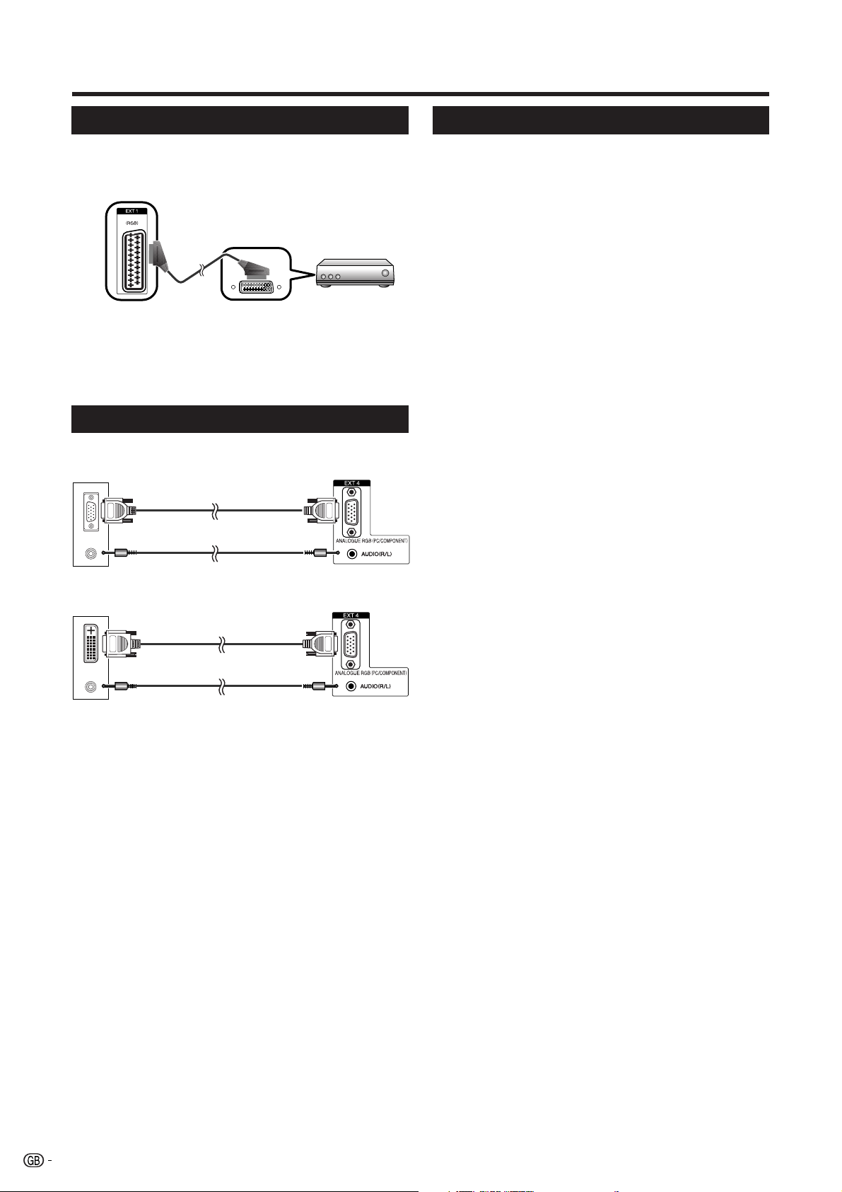
Connecting a decoder
You can use the EXT 1 terminal when connecting a
decoder and other audiovisual equipment.
EXT 1
SCART cable*
Decoder
NOTE
• In cases when the decoder needs to receive signal from
the TV, make sure to set “Decoder” to “EXT1” in the
Programme Setup “Manual Adjust” menu. (See page 16.)
• Do not connect the decoder to the EXT 2 terminal.
Connecting a PC
Use the EXT 4 terminals to connect a PC.
PC
RGB cable*
ø 3.5 mm stereo minijack cable*
PC
RGB/DVI conversion cable*
EXT 4
EXT 4
Using AV Link function
This TV incorporates three typical AV Link functions
for smooth connections between the TV and other
audiovisual equipment.
One Touch Play
While the TV is in standby mode, it automatically turns
on and plays back the image from the audiovisual
source (e.g. VCR, DVD).
WYSIWYR (What You See Is What You Record)
When the remote control unit of the connected VCR
has the WYSIWYR button, you can automatically start
recording by pressing the WYSIWYR button.
Preset Download
Automatically transfers the channel preset information
from the tuner on the TV to the one on the connected
audiovisual equipment (e.g. VCR) via the EXT 2
terminal.
NOTE
• Refer to operation manuals of each external equipment
for the details.
• Only works when the audiovisual equipment is connected
to the EXT 2 terminal on the TV with AV Link via a fully
wired SCART.
• The use of the AV Link function is only possible if the TVset has enforced a complete auto-installation with the
connected audiovisual equipment (page 8, Initial auto
installation).
The availability of the AV Link function depends on the
audiovisual equipment used. Depending on the
manufacturer and type of equipment used, it is possible
that the described functions may be completely or partially
unusable.
ø 3.5 mm stereo minijack cable*
NOTE
• The cables marked with * are commercially available
items.
• The PC input terminals are DDC1/2B-compatible.
• Refer to page 33 for a list of PC signals compatible with
the TV.
• When connecting to a PC, the correct input signal type is
automatically detected.
10
Loading...