


LC-32L400M
SERVICE MANUAL
Parts marked with " " are important for maintaining the safety of the set. Be sure to replace these parts with specified ones for maintaining the
safety and performance of the set.
This document has been published to be used for
after sales service only.
The contents are subject to change without notice.
SAFETY PRECAUTION
IMPORTANT SERVICE SAFETY
PRECAUTION............................................................ i
PRECAUTIONS FOR USING LEAD-FREE
SOLDER ................................................................... ii
OUTLINE
MAJOR SERVICE PARTS ........................................iii
CHAPTER 1. SPECIFICATIONS
[1] SPECIFICATIONS .................................................1-1
CHAPTER 2. OPERATION MANUAL
[1] OPERATION MANUAL ..........................................2-1
CHAPTER 3. DIMENSIONS
[1] DIMENSIONS ........................................................3-1
CHAPTER 4. REMOVING OF MAJOR PARTS
[1] REMOVING OF MAJOR PARTS ...........................4-1
CHAPTER 5. ADJUSTMENT
[1] ADJUSTMENT PROCEDURE ...............................5-1
CHAPTER 6. TROUBLESHOOTING TABLE
[1] TROUBLESHOOTING TABLE...............................6-1
CHAPTER 7. OVERALL WIRING/BLOCK DIAGRAM
[1] OVERALL WIRING DIAGRAM ..............................7-1
[2] SYSTEM BLOCK DIAGRAM .................................7-2
CHAPTER 8. PRINTED WIRING BOARD ASSEMBLIES
[1] MAIN Unit...............................................................8-1
[2] POWER SUB Unit..................................................8-3
[3] R/C, LED Unit.........................................................8-5
CHAPTER 9. SCHEMATIC DIAGRAM
[1] DESCRIPTION OF SCHEMATIC DIAGRAM.........9-1
[2] MAIN Unit...............................................................9-2
[3] POWER SUB Unit................................................9-12
[4] R/C, LED Unit.......................................................9-16
Parts Guide
TopPage
CONTENTS
In the interests of user-safety (Required by safety regulations in some countries) the set should
be restored to its original condition and only parts identical to those specified should be used.
LCD COLOUR TELEVISION
No. S40F6LC32L40M
LC-32L400M
LC-32L400M
MODEL

LC-32L400M
i
LC-32L400M
Service Manual
SAFETY PRECAUTION
IMPORTANT SERVICE SAFETY PRECAUTION
WARNING
1. For continued safety, no modification of any circuit should be
attempted.
2. Disconnect AC power before servicing.
BEFORE RETURNING THE RECEIVER (Fire &
Shock Hazard)
Before returning the receiver to the user, perform the following
safety checks:
3. Inspect all lead dress to make certain that leads are not pinched,
and check that hardware is not lodged between the chassis and
other metal parts in the receiver.
4. Inspect all protective devices such as non-metallic control knobs,
insulation materials, cabinet backs, adjustment and compartment
covers or shields, isolation resistor-capacitor networks, mechanical
insulators, etc.
5. To be sure that no shock hazard exists, check for leakage current in
the following manner.
• Plug the AC cord directly into a 110-240 volt AC outlet.
• Using two clip leads, connect a 1.5k ohm, 10 watt resistor paral-
leled by a 0.15µF capacitor in series with all exposed metal cabinet
parts and a known earth ground, such as electrical conduit or elec-
trical ground connected to an earth ground.
• Use an AC voltmeter having with 5000 ohm per volt, or higher, sen-
sitivity or measure the AC voltage drop across the resistor.
• Connect the resistor connection to all exposed metal parts having a
return to the chassis (antenna, metal cabinet, screw heads, knobs
and control shafts, escutcheon, etc.) and measure the AC voltage
drop across the resistor.
All checks must be repeated with the AC cord plug connection
reversed. (If necessary, a nonpolarized adaptor plug must be used
only for the purpose of completing these checks.)
Any reading of 0.74 Vrms (this corresponds to 0.5 mA rms AC.) or
more is excessive and indicates a potential shock hazard which
must be corrected before returning the monitor to the owner.
///////////////////////////////////////////////////////////////////////////////////////////////////////////////////////////////////////////////////////////////////////////////////////////////////////////////////////////////////////////
SAFETY NOTICE
Many electrical and mechanical parts in LCD colour television have
special safety-related characteristics.
These characteristics are often not evident from visual inspection, nor
can protection afforded by them be necessarily increased by using
replacement components rated for higher voltage, wattage, etc.
Replacement parts which have these special safety characteristics are
identified in this manual; electrical components having such features
are identified by " " and shaded areas in the Replacement Parts List
and Schematic Diagrams.
For continued protection, replacement parts must be identical to those
used in the original circuit.
The use of a substitute replacement parts which do not have the same
safety characteristics as the factory recommended replacement parts
shown in this service manual, may create shock, fire or other hazards.
///////////////////////////////////////////////////////////////////////////////////////////////////////////////////////////////////////////////////////////////////////////////////////////////////////////////////////////////////////////
Service work should be performed only by qualified service technicians who are thoroughly familiar with all safety checks and the
servicing guidelines which follow:
DVM
AC SCALE
1.5k ohm
10W
TO EXPOSED
METAL PARTS
CONNECT TO
KNOWN EARTH
GROUND
0.15
µ
F
TEST PROBE

LC-32L400M
ii
PRECAUTIONS FOR USING LEAD-FREE SOLDER
Employing lead-free solder
• “PWBs” of this model employs lead-free solder. The LF symbol indicates lead-free solder, and is attached on the PWBs and service manuals. The
alphabetical character following LF shows the type of lead-free solder.
Example:
Using lead-free wire solder
• When fixing the PWB soldered with the lead-free solder, apply lead-free wire solder. Repairing with conventional lead wire solder may cause dam-
age or accident due to cracks.
As the melting point of lead-free solder (Sn-Ag-Cu) is higher than the lead wire solder by 40 °C, we recommend you to use a dedicated soldering
bit, if you are not familiar with how to obtain lead-free wire solder or soldering bit, contact our service station or service branch in your area.
Soldering
• As the melting point of lead-free solder (Sn-Ag-Cu) is about 220 °C which is higher than the conventional lead solder by 40 °C, and as it has poor
solder wettability, you may be apt to keep the soldering bit in contact with the PWB for extended period of time. However, Since the land may be
peeled off or the maximum heat-resistance temperature of parts may be exceeded, remove the bit from the PWB as soon as you confirm the
steady soldering condition.
Lead-free solder contains more tin, and the end of the soldering bit may be easily corroded. Make sure to turn on and off the power of the bit as
required.
If a different type of solder stays on the tip of the soldering bit, it is alloyed with lead-free solder. Clean the bit after every use of it.
When the tip of the soldering bit is blackened during use, file it with steel wool or fine sandpaper.
• Be careful when replacing parts with polarity indication on the PWB silk.
Lead-free wire solder for servicing
Indicates lead-free solder of tin, silver and copper. Indicates lead-free solder of tin, silver and copper.
PARTS CODE
PRICE
RANK
PART
DELIVERY
DESCRIPTION
ZHNDAi123250E BL J φ0.3mm 250g (1roll)
ZHNDAi126500E BK J φ0.6mm 500g (1roll)
ZHNDAi12801KE BM J φ1.0mm 1kg (1roll)
LC-32L400M
iii
LC-32L400M
Service Manual
OUTLINE
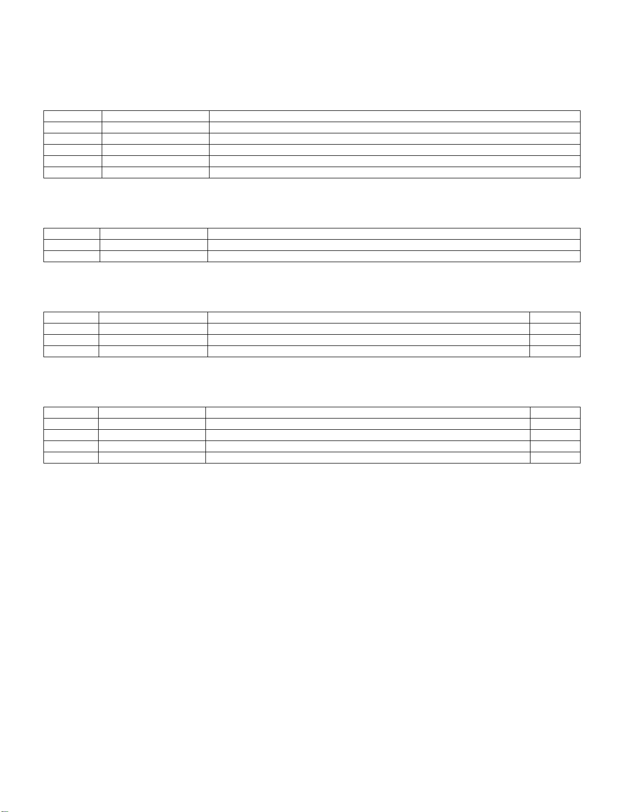
MAJOR SERVICE PARTS
PWB UNIT
OTHER UNIT
IC FOR EXCLUSIVE USE OF THE SERVICE
SERVICE JIGS
Ref No. Part No. Description
N DUNTKF537FM02 MAIN Unit
N DUNTKF538FM02 POWER SUB Unit
N DUNTKF539FM02 R/C, LED Unit
N RDENC2590TPZZ INVERTER Unit
Ref No. Part No. Description
N B3KU32L50 32” LCD Panel Module (R1LK315T3LA5BX)
Ref No. Part No. Description Q'ty
IC508 RH-iXD169WJQZS IC, PC EDID 1
IC1503 RH-iXD170WJQZS IC, HDMI EDID 1
Ref No. Part No. Description Q’ty
N QCNW-L077WJQZ Connecting Cord, MAIN-LCD CONTROL (LW) 1
N QCNW-K814WJQZ Connecting Cord, POWER-INVERTER (PI) 1
N QCNW-J413WJQZ Connecting Cord, MAIN-SPEAKER (SP) 1

LC-32L400M
1 – 1
LC-32L400M
Service Manual
CHAPTER 1. SPECIFICATIONS
[1] SPECIFICATIONS
Item
Model
LC-32L400M
LCD panel
32" (800 mm) Advanced Super View & BLACK TFT LCD
Resolution
1,049,088 pixels (1366 768)
Video Colour System PAL/SECAM/NTSC 3.58/NTSC 4.43/PAL 60
TV
Function
TV-Standard PAL: B/G, D/K, I SECAM: B/G, D/K, K/K
1
NTSC: M
Receiving
Channel
VHF/UHF 44.25
_
863.25 MHz
CATV S1
_
S41ch (including Hyperband)
TV-Tuning System Auto Preset 99 ch
STEREO/BILINGUAL NICAM: B/G, I, D/K A2 stereo: B/G
Viewing angles H : 176º V : 176º
Audio amplifier
5W 2
Speakers
9 5 cm 2pcs
Terminals Rear Antenna input
UHF/VHF 75 DIN type
INPUT 1
HDMI (HDMI input) (480
I
,576
I
, 480P, 576P, 720P/50Hz, 720P/60Hz, 1080
I
/50Hz,
1080
I
/60Hz), AUDIO in ( 3.5 mm jack)
INPUT 2 S-VIDEO in, VIDEO in, AUDIO in
INPUT 3 VIDEO in, AUDIO in
INPUT 4 AUDIO in, COMPONENT in (480
I
, 576
I
, 480P, 576P, 720P/50Hz, 720P/60Hz,
1080
I
/50Hz, 1080
I
/60Hz)
INPUT 5 (PC input)
15 pin mini D-sub, AUDIO in (common use with INPUT 1) (
3.5 mm jack)
RS-232C 9 pin D-sub male connector
OSD language English/Simplified Chinese/Arabic/French/Portuguese/Russian/Persian/Thai/
Vietnamese/Indonesian
Power Requirement AC 110
_
240 V, 50/60 Hz
Power Consumption 112 W (0.9 W Standby)
Dimensions
without stand
797 (W) 535 (H) 115 (D) mm
with stand
797 (W) 580 (H) 262 (D) mm
Weight
without stand 10.0 kg
with stand 11.0 kg
Operating Temperature 0°C
_
40°C
As a part of policy of continuous improvement, SHARP reserves the right to make design and specification changes for
product improvement without prior notice. The performance specification figures indicated are nominal values of production
units. There may be some deviations from these values in individual units.
LC-32L400M
2 – 1
LC-32L400M
Service Manual
CHAPTER 2. OPERATION MANUAL
[1] OPERATION MANUAL
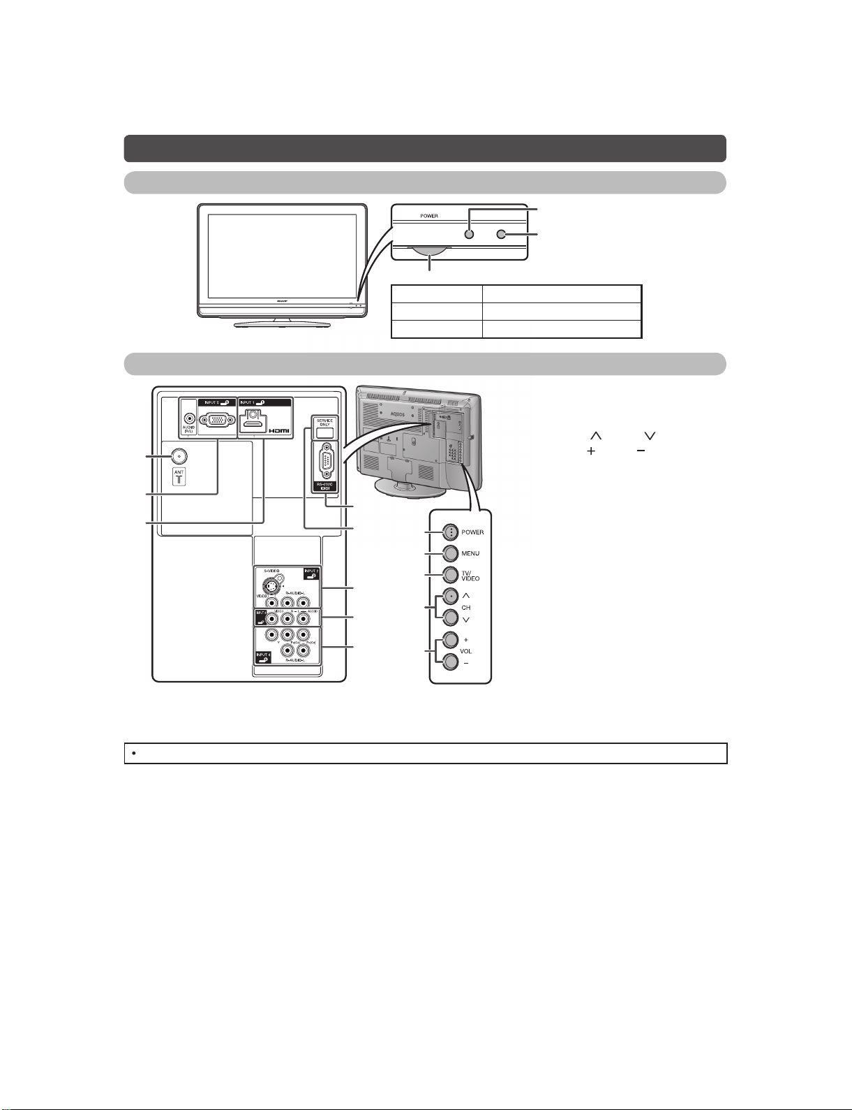
Part names
TV (Front)
Remote control sensor
OPC sensor
POWER indicator
Light off Power off
Lighted (Red) The TV is in standby mode.
Lighted (Green) The TV is on.
TV (Rear)
ANALOGUE RGB (PC)
6
9
11
8
7
10
12
13
1
2
3
4
5
1 POWER (On/Off) button
2MENUbutton
3 TV/VIDEO button
4 Channel up ( )/down ( ) buttons
5 Volume up ( )/down ( ) buttons
6 Antenna input terminal
7 INPUT 5 (PC) terminals*
8 INPUT 1 (HDMI) terminal*
9 RS-232C terminal
10 SERVICE ONLY terminal**
11 INPUT 2 terminals
12 INPUT 3 terminals
13 INPUT 4 terminals
* The INPUT 1 and INPUT 5 terminals can both use the same audio input terminal. However, the proper item must be
selected in the "PC Audio Select" menu.
**Usually do not connect anything to this terminal as it is reserved only for service personnel.
The illustrations in this operation manual are for explanation purposes and may vary slightly from the actual operations.
LC-32L400M
2 – 2
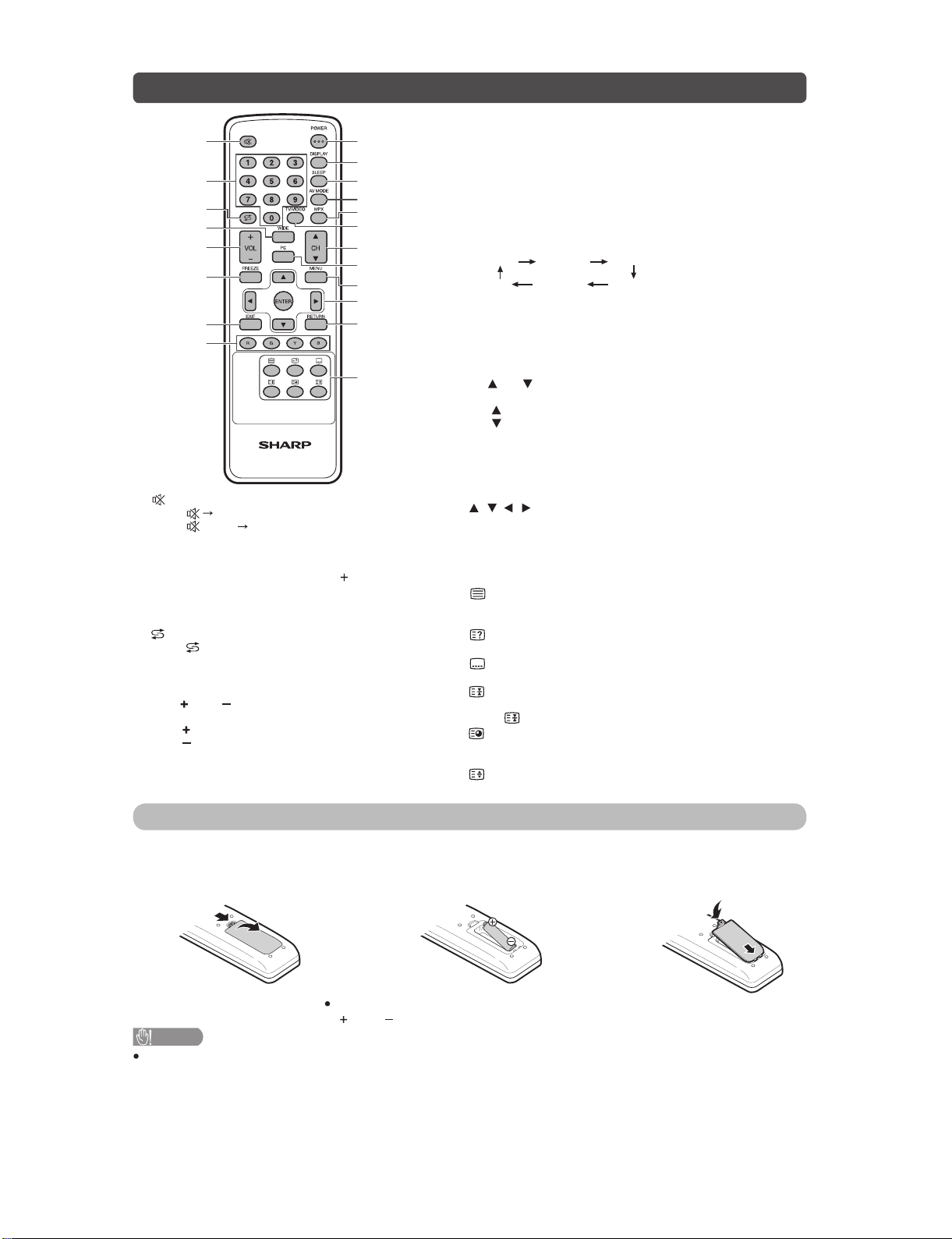
Remote control unit
1
2
3
4
5
6
7
8
9
10
11
12
13
14
15
16
17
18
19
20
7 EXIT
Return to the default screen.
8 Colour (Red/Green/Yellow/Blue)
TELETEXT mode: Select a page.
9 POWER (STANDBY/ON)
To switch the power on and off.
10 DISPLAY
Display the channel or input information.
11 SLEEP
Set the Sleep timer.
0hr.30min. 1hr.00min.
2hr.30min.
1hr.30min.
2hr.00min.
Off
12 AV MODE
Select an audio and video setting.
13 MPX
Select the sound multiplex mode.
14 TV/VIDEO (INPUT SOURCE)
Select an input source.
15 CH /CH
TV input mode: Select the channel.
(CH ) Increase the channel number.
(CH ) Decrease the channel number.
TELETEXT mode: Select the page.
16 PC
Directly select the PC terminal.
17 MENU
Display the menu screen.
18 / / / (Cursor)
Select a desired item on the setting screen.
ENTER
Execute a command.
19 RETURN
MENU mode: Return to the previous menu screen.
20 (TELETEXT)
Select the TELETEXT mode. (all TV image, all TEXT image,
TV/TEXT image)
(Reveal hidden for TELETEXT)
TELETEXT mode: Display hidden characters.
(SUBTITLE for TELETEXT)
To turn the subtitles on and off.
(Hold)
TELETEXT mode: Stop updating Teletext pages automatically.
Press again to release the hold mode.
(Subpage)
Display the Teletext subpage directly when in Teletext mode.
(Top/Bottom/Full)
TELETEXT mode: Set the area of magnification.
1 (Mute)
Press Mutes sound.
Press again Restores sound.
Mute will be cancelled after 30 minutes. However,
the TV will not suddenly output loud sound as the
volume level will be set to 0 automatically. Increase
the volume level by pressing VOL
.
20
_
9
Set the channel.
TELETEXT mode: Set the page.
3 (Flashback)
Press to return to the previous selected channel
or external input mode.
4WIDE
Change the wide image mode.
5 VOL /VOL
Set the volume.
(VOL ) Increase the volume.
(VOL ) Decrease the volume.
6 FREEZE
Freeze a motion picture on the screen.
Inserting the battery
Before using the TV for the first time, insert a "AA" size battery (supplied). When the battery become depleted
and the remote control fails to operate, replace the battery with new "AA" size battery.
1
Open the battery cover.
2
Insert the supplied "AA" size battery.
3
Close the battery cover.
Place battery with their terminals corresponding to the
( ) and ( ) indications in the battery compartment.
CAUTION
Battery (battery pack or batteries installed) shall not be exposed to excessive heat such as sunshine, fire or the like.
LC-32L400M
2 – 3
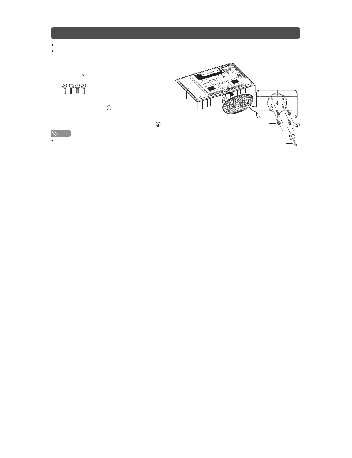
Attaching the stand
Before attaching (or detaching) the stand, unplug the AC cord from the AC outlet.
Before performing work spread cushioning over the base area to lay the TV on. This will prevent it from
being damaged.
1
Confirm the screws supplied with the TV.
Screws ( 4)
(usedinstep3)
2
Insert the stand base to the stand post on the
bottom of the TV. ( )
3
Insert and tighten the 4 screws into the 4
holes on the bottom of the stand base. ( )
NOTE
To detach the stand, perform the steps in reverse
order.
Screw driver
Screw
Soft cushion

LC-32L400M
3 – 1
LC-32L400M
Service Manual
CHAPTER 3. DIMENSIONS
[1] DIMENSIONS
Unit: mm
LC-32L400M
4 – 1
LC-32L400M
Service Manual
CHAPTER 4. REMOVING OF MAJOR PARTS
[1] REMOVING OF MAJOR PARTS
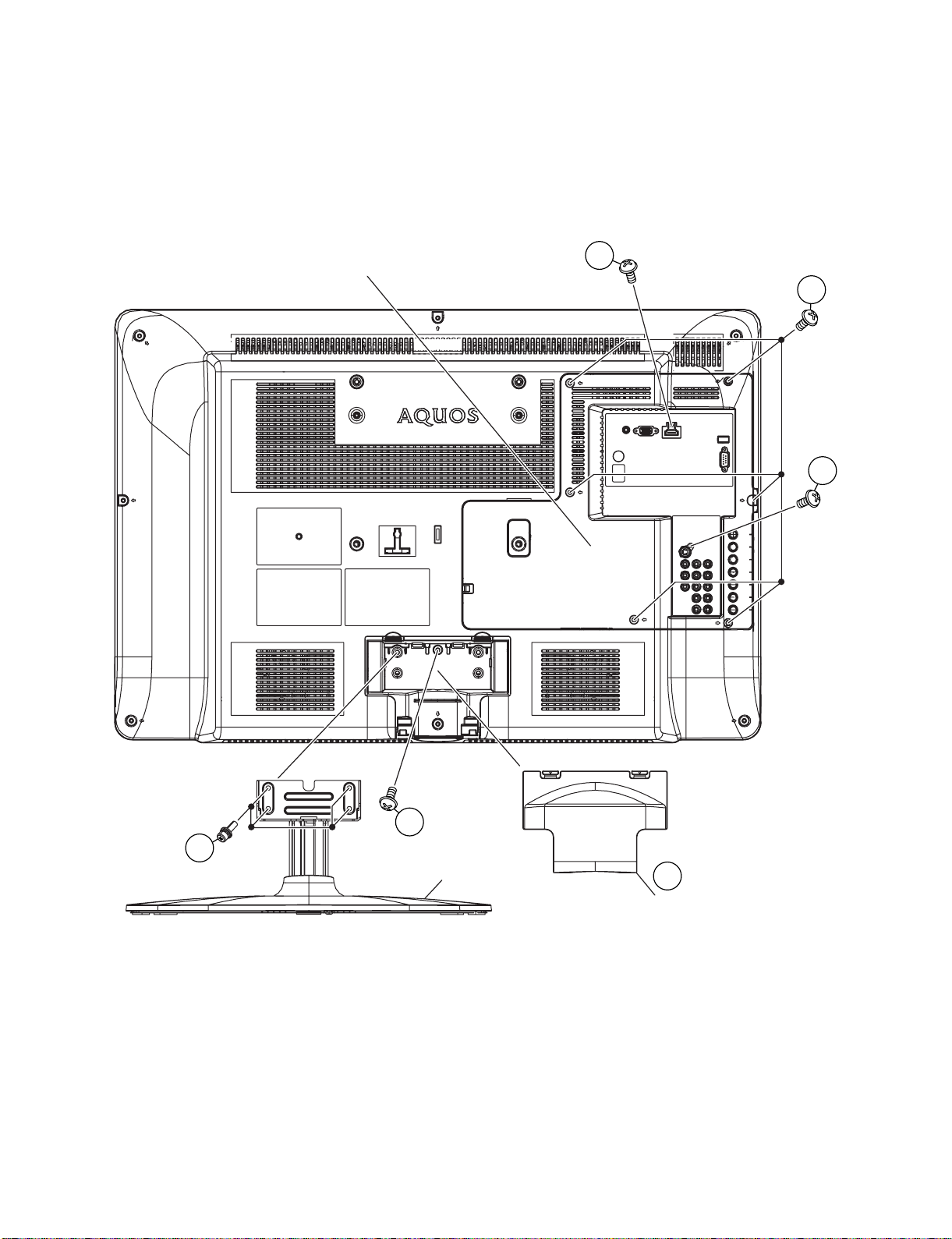
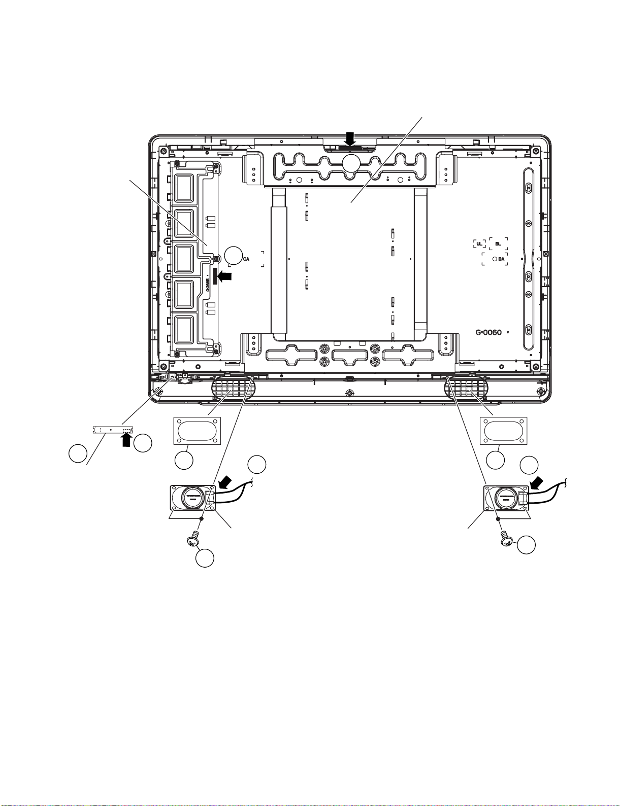
1. Removing of the Stand and Back Cover
1. Detach the Stand Hinge Cover [1].
2. Remove the 4 lock screws [2] and detach the Stand.
3. Remove the 1 lock screw [3], 1 lock screw [4], 1 lock screw [5], 6 lock screws [6] and detach the Back Cover.
Stand
Stand Hinge Cover
Back Cover
6
5
3
4
2
1
LC-32L400M
4 – 2
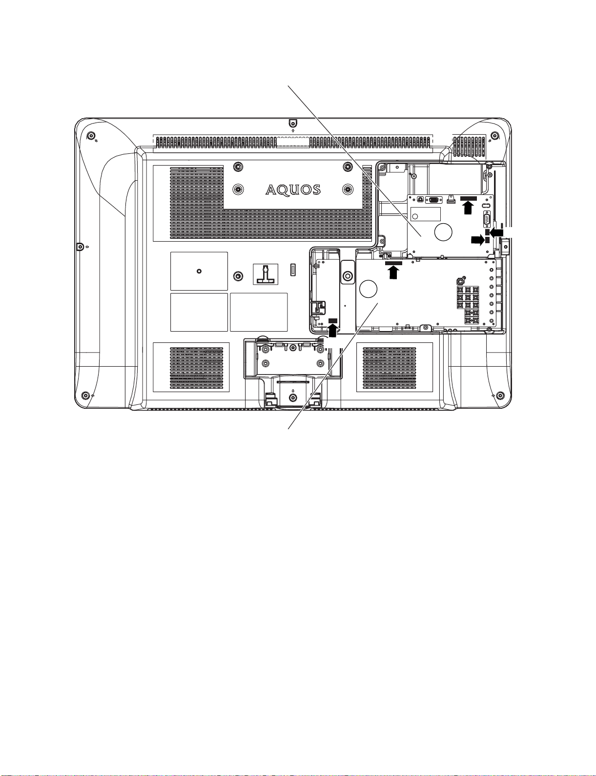
2. Disconnect the connectors
1. Disconnect the connectors from the MAIN Unit, POWER SUB Unit [1].
MAIN Unit
POWER SUB Unit
1
PI
AC
PA
SP
RA
1
LC-32L400M
4 – 3
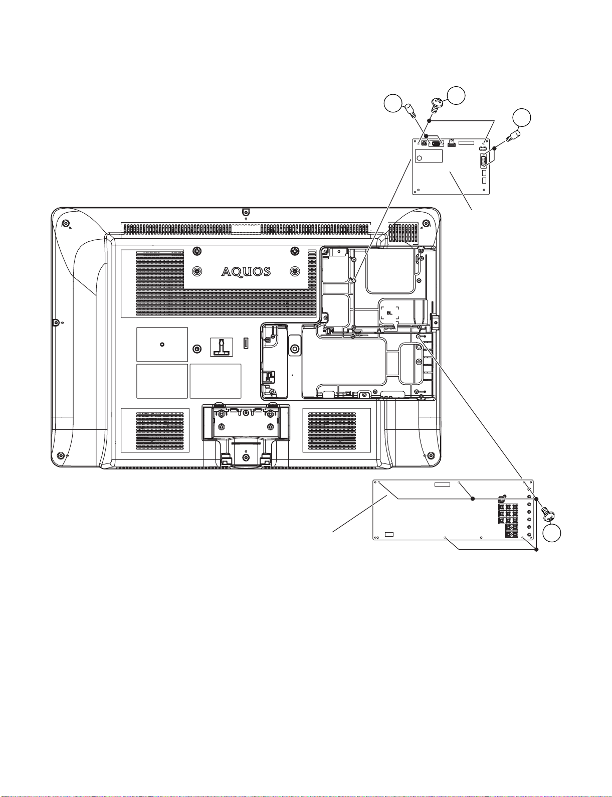
3. Removing of the MAIN Unit and POWER SUB Unit
1. Remove the 2 lock shafts [1], 2 lock shafts [2], 2 lock screws [3] and detach the MAIN Unit.
2. Remove the 5 lock screws [4] and detach the POWER SUB Unit.
MAIN Unit
POWER SUB Unit
4
3
1
2

LC-32L400M
4 – 4
4. Removing of the Rear Cabinet
1. Remove the 7 lock screws [1] and detach the Rear Cabinet.
Rear Cabinet
1
LC-32L400M
4 – 5
5. Removing of the Speaker and R/C, LED Unit
1. Disconnect the connectors from the INVERTER Unit and LCD Panel Module [1].
2. Disconnect SP connectors [2]. Remove the 4 lock screws [3] and detach the Speaker, remove the 2 Molt Plane [3a].
3. Detach the R/C, LED Unit [4] and disconnect RA connector [5].
Speaker
3
3
2
3a
4
5
2
1
1
Speaker
R/C, LED Unit
INVERTER Unit
LCD Panel Module
LVDS
PI
RA
SP
SP
3a

LC-32L400M
4 – 6
6. Removing of the Top Bracket, Bottom Bracket and LCD Panel Module
1. Remove the 4 lock screws [1].
2. Remove the 4 lock screws [2] and detach the Top Bracket, Bottom Bracket.
3. Remove the 2 lock screws [3] and detach the LCD Panel Module.
2
1
3
Bottom Bracket
LCD Panel Module
Top Bracket
2
1
3

LC-32L400M
5 – 1
LC-32L400M
Service Manual
CHAPTER 5. ADJUSTMENT
[1] ADJUSTMENT PROCEDURE
1. Entering and cancel the adjustment process mode
While holding down the TV/VIDEO and Volume DOWN keys at the same time, plug in the AC cord to turn on the power. (“K123” standing for
inspection process mode is displayed on the middle right section of the screen.)
Press the Channel DOWN and Volume DOWN keys at the same time. (The adjustment process mode screen appears.)
To cancel it, turn off the power using the Power switch or remote control.
2. Remote controller key operation and description of display in adjustment process mode.
1. key operation
* Input mode is switched automatically when relevant adjustment is started so far as the necessary input signal is available.
3. Signal adjustment
3.1. Signal check
Confirmation of signal from generator (setting to spec level)
3.1.1 PROCESS MODE
*On double screen models, the tuner, composite signal and component signal adjustment are made for their single screen mode and double screen
mode as well.
3.1.2 Component 15K 50Hz signal adjustment (COMP-SD)
Remote controller key Main unit key Function
CH ( / )
CH ( / )
Changing channel (UP/DOWN)
VOL (+ / –) VOL (+ / –) Changing volume (UP/DOWN)
Cursor ( / )
—————— Turning a page (PREVIOUS/NEXT)
Cursor ( / )
—————— Changing a selected line setting (+10/-10)
TV/VIDEO button on remote
controller
TV/VIDEO button Input source switching (toggle switching)
(T V-DAV- 1/S AV-1 → AV- 2 → COMPONENT → HDMI → PC)
ENTER —————— ——————
• PAL Composite signal : 0.7Vp-p ± 0.02Vp-p (Pedestal to white level)
• 15K Component signal (50Hz) : Y level:
Pb, Pr level:
0.7Vp-p ± 0.02Vp-p (Pedestal to white level)
0.7Vp-p ± 0.02Vp-p
• 33K component signal : Y level:
Pb, Pr level:
0.7Vp-p ± 0.02Vp-p (Pedestal to white level)
0.7Vp-p ± 0.02Vp-Com
Adjustment item Adjustment conditions Adjustment procedure
1 Adjustment mode 1) Press the test key at the test remote control.
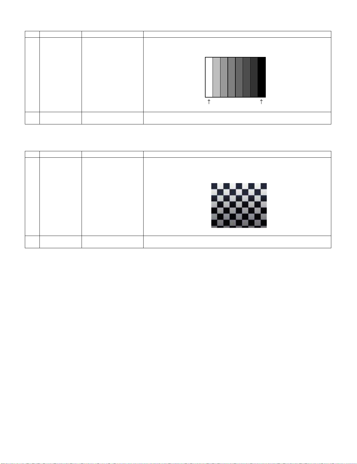
Adjustment item Adjustment conditions Adjustment procedure
1 Adjustment [Signal]
COMP 15K 50Hz (576i)
100% Full-field Colour Bar
[Terminal]
INPUT 4 COMPONENT
Feed the COMPONENT 15K 50Hz (576i) 100% Full-field Colour Bar signal (100% colour
saturation) to INPUT 4 COMPONENT terminal.
2 Auto adjustment
performance
Process Mode page 4
(COMP SD)
1) At the related page, move cursor to [COMP SD ADJ], press ENTER.
2) [OK] appears when finished.
100% white Black
LC-32L400M
5 – 2
3.1.3 Component 33K 60Hz signal adjustment (COMP-HD)
3.1.4 PC (ANALOG RGB) signal adjustment (PC-RGB)
Adjustment item Adjustment conditions Adjustment procedure
1 Adjustment [Signal]
COMP 33K 60Hz (1080i)
100% Full-field Colour Bar
[Terminal]
INPUT 4 COMPONENT
Feed the COMPONENT 33K 60Hz (1080i) 100% Full-field Colour Bar signal (100%
colour saturation) to INPUT 4 COMPONENT terminal.
2 Auto adjustment
performance
Process Mode page 5
(COMP HD)
1) At the related page, move cursor to [COMP HD ADJ], press ENTER.
2) [OK] appears when finished.
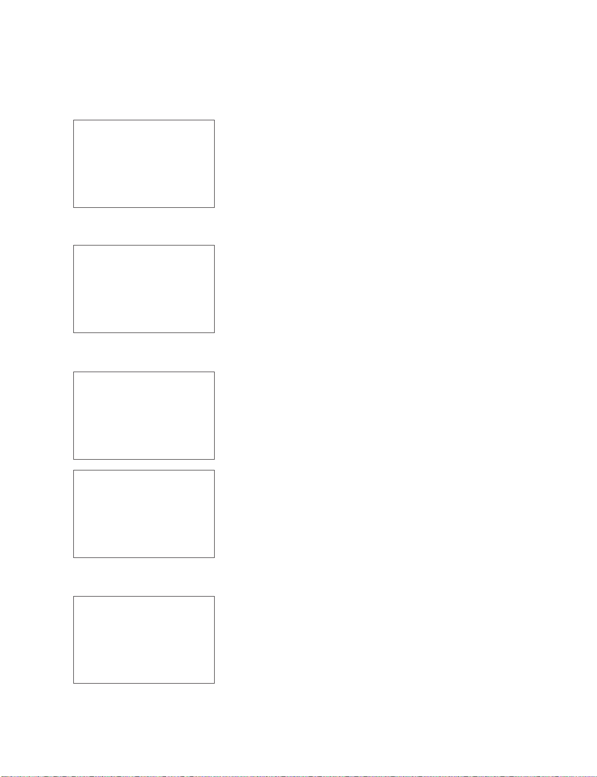
Adjustment item Adjustment conditions Adjustment procedure
1 Adjustment [Signal]
XGA 60Hz
100% Checkered Pattern
[Terminal]
PC INPUT
Feed the XGA 60Hz 100% Checkered pattern signal (100% colour saturation) to PC
INPUT.
*Please make sure SYNC is OFF.
2 Auto adjustment
performance
Process Mode page 6
(PC-RGB)
1) At the related page, move cursor to [RGB ADJ], press ENTER.
2) [OK] appears when finished.
100% white Black

LC-32L400M
5 – 3
3.2. White balance adjustment
4. Factory setting
AC power is plug off after shipment setting is done.
CAUTION: Do not plug on again after shipment setting is done. If do, please re-do the shipment setting. Do not off with remote control.
Adjustment item Adjustment conditions Adjustment procedure
1 Adjustment Brightness : MAX
Set the luminance meter on
the center of the screen
For the details of white balance adjustment procedure, please refer to white balance
adjustment spec for current model.
1) Confirm the set condition.
2) Connect the luminance meter CA-210.
3) Through RS-232C command, adjustment mode screen is displayed.
2 Auto Adjustment
performance
[command]
Adjustment Mode
KRSW0001
KKT10037
Setting
KYOF0001
OSDS0001
SBSL0016
Multi point adj. Mode
MSET0001
Point 2
LEV20204
WBI20204
MG2G****
MG2B****
MG2R****
Point 1
LEV10128
WBI10128
MG1G****
MG1B****
MG1R****
Write
MSET0003
[Adjustment Procedure]
1) Using the remote control, set the LCD TV to adjustment mode.
2) Set the specified gradation for point 2, fix the most faint colour to get reference
value, adjust others 2 colour to minus adjustment for reference value of point 2.
3) Set the specified gradation for point 1. Set G of point 1 to the default value [(2048xG
value of point 2/3264), with fractions rounded] and adjust RB to the reference value
of point 1.
4) Adjusted value is writing at [command] MSET0003, and then shut down the AC
power.
*Initial value at RGB 2 point : 3264
*Initial value at RGB 1 point : 2048
[Adjustment Value]
✩Specification data by engineering dept is set as reference.
[Reference value for adjustment reference]
Equipment: Luminance meter [Minolta CA-210]
Ref. : For inspection, set the LCD TV as below.
AV MODE: [DYNAMIC] (Reset)
Monochrome: ON
Aging Time: Minimum 60 minutes
Adjustment item Adjustment condition Adjustment procedure
Factory setting AC power off to exit the fac-
tory setting.
1) Setting is done with test remote control.
2) When Green background appears on screen and “K” mark disappears, setting is com-
pleted.
The followings are initialized to factory setting
1) User setting
2) Channel data (e. g. broadcast frequencies)
3) Manufacturer’s option settings
4) Password data
5) Setting values are set based on model destination
Level
Spec
Data
Adjustment
Spec.
Inspection
Spec.
Point 2
ref.
values
Point 1
ref.
values
204
128
x=0.272
y=0.277
x=0.272
y=0.277
r0.0010
r0.0045
r0.0020
r0.0090
LC-32L400M
5 – 4
5. Software upgrading
1) Plug off the LCD TV.
2) Insert the USB device to the USB terminal at the LCD TV.
(Make sure that latest software is installed in the USB device)
3) Hold the LCD TV power key and plug on the LCD TV.
4) LCD TV is on and detecting the USB device.
5) A few seconds later, the software upgrading will start automatically.
6) Let the process running & entering verification.
7) Software is successfully installed when the following appears at the end of the process.
8) Plug off the LCD TV & plug on again as usual.
9) LCD TV is running with the latest software.
USB device found
Do not power off
Chip programming
>>>>>>>>
Verifying
Verified
Please re-boot the system
Update Finished

LC-32L400M
6 – 1
LC-32L400M
Service Manual
CHAPTER 6. TROUBLESHOOTING TABLE
[1] TROUBLESHOOTING TABLE
No power (front LED failure to light up) or no startup (front LED failure to turn from red to green)
Is the AC cord connector tightly connected to the set? NO Reconnect the AC cord tightly and turn on the power again.
YES
Is the output voltage at pin (7), (8), (9) and (10) of P5201 (13.0V
line) as specified?
NO Replace the power unit.
YES
Are the wire harnesses and other cables properly connected in
the set?
NO Reconnect the wire harnesses and other cables properly in the
set.
YES
Is there the AC_DET and PNL_ON signal input at pins (14) and
(1) of P5201?
NO Check the AC_DET signal line PNL_ON signal line.
YES
Are the DC/DC converter outputs and the output voltages along
the control lines as specified?
NO Check the DC/DC converters and the control lines. Replace
defective parts as required.
1) B1.26V (IC9606)
2) D2.6V (IC9603)
3) STB+3.3V (IC9602)
4) D3.3V (IC9653)
5) B5V (IC9652)

LC-32L400M
6 – 2
With [RF] signal input No video onscreen (1)
No video in the UHF/VHF reception
Is there IF output from the tuner pin(12) of TU1101 as specified? NO Check TU1101 and its peripheral circuits.
YES
Is there VIF input at pin 57 & 58 of IC3301? NO Check the circuit between TU1101 & IC3301.
YES
Are there the signal outputs of IC3301? NO Check IC3301 and its peripheral circuit.
YES
Check LVDS cable, LCD controller (incl. panel) and their periph-
eral circuits.
With <Video> signal input No video onscreen (2)
No external input video onscreen <INPUT 2>
Is INPUT 2 selected on the input select menu screen? NO Select INPUT 2 on the input select menu screen to pick up the
right input signal.
YES
Is there the video signal input at pin (33) of IC3301? NO Check the line between pin (3) of J5510 and pin (33) of IC3301.
YES
Are there signal outputs of IC3301? NO Check IC3301 and its peripheral circuits.
YES
Check LVDS cable, LCD controller (incl. panel) and their periph-
eral circuits.
 Loading...